With reference to the post:
https://www.elektroda.com/rtvforum/topic4075622.html
I would like to document my experience, or rather inexperience, in getting in OpenBK on to it.
I traced the connections of the PCB as follows:
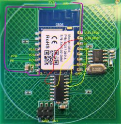
I made some serious mistakes in attempting to de-solder the CBS Module.
I wanted to see whether I can lift the CBS module a little bit by ulsoldering only the pins on the top side of the module. Attempted to use the soldering iron only.
Ended up in a disastrous situation where I accidentally removed most of the tracks and pads off the PCB.
I I attempted to reconstruct the the broken tracks by using thin adhesive copper strips that I ordered from Aliexpress.
However the reconstructed PCB did not work.
At that point I almost gave up the attempt to flash OpenBK on to it.
Time flew by and then last week I decided that I will attempt to repair it again.
This time I had a heat gun and tried to remove the module from the board again for reconstruction of the tracks again.
Little did it come to my mind that the switch has plastic/acrylic parts on the other side on the touch switches.
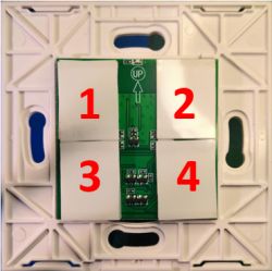
Although I managed to remove the module, the caused two of the switch positions to have melted plastic pieces.
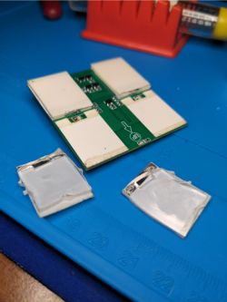
Nevertheless I wanted to reattempt to repair the tracks.
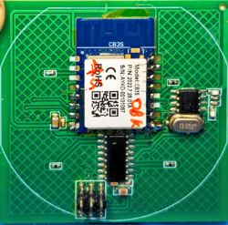
So after the cleanup my PCB now looked like this:
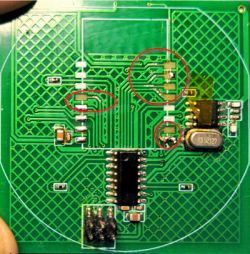
I had scraped off the coatings to expose the tracks at broken points and applied solder for the last repair.
This time I decided that I will use thin copper wire strands to repair the tracks.
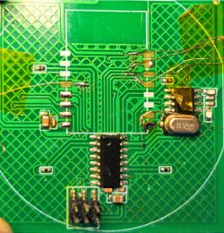
This time I was better equipped and has some kapton tape to help secure the wires in place after soldering.
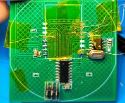
After securing the module back using only the power and ground pins I pulled the wire strands against the solder pad slots on the module and soldered them.
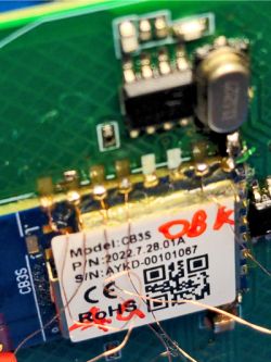
All looked good
except that Relay 1 was not operational. On further investigation found that pin P26 some how does not get connected to the transistor on the other side of the PCB.
So I decided to use a wire externally as I did not want to remove the module again. The track did not appear to be broken but I wanted to do the short cut to complete the repair.
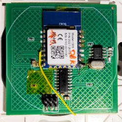
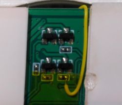
This required some precision soldering skills, to solder a tiny wire to the tiny resistor. I am glad that I got the hang of it also.
So now the switch is functional except that switch 1 & 2 require plastic pieces from another source. I suppose 2mm acrylic sheet would do the job.
Also there is one issue with the WiFi LED at the top.
The LED itself is not broken but does not get lit up even if I set P11 to "WiFiLED_n".
What I observed is that instead of the WiFiLED all button switches blink during WiFi connection attempt.
Tried to investigate that by tracing the connections.
I found the connections to be like this:
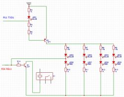
So the relay driving GPIO functions are understood but I have trouble understanding the P11 connection. It has a direct connection towards the LED and also towards the 5th Transistor on the board.
Need to recheck whether my tracing is correct.
Also I am trying to think about how best to flash the other devices that I have of the same type without having to completely remove the CBS module.
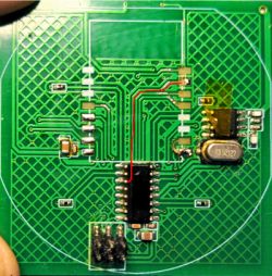
As you can see the RXD1 pin has been routed to the button controller without leaving any room for breaking the track. Otherwise that would have been the easiest way.
https://www.elektroda.com/rtvforum/topic4075622.html
I would like to document my experience, or rather inexperience, in getting in OpenBK on to it.
I traced the connections of the PCB as follows:

I made some serious mistakes in attempting to de-solder the CBS Module.
I wanted to see whether I can lift the CBS module a little bit by ulsoldering only the pins on the top side of the module. Attempted to use the soldering iron only.
Ended up in a disastrous situation where I accidentally removed most of the tracks and pads off the PCB.
I I attempted to reconstruct the the broken tracks by using thin adhesive copper strips that I ordered from Aliexpress.
However the reconstructed PCB did not work.
At that point I almost gave up the attempt to flash OpenBK on to it.
Time flew by and then last week I decided that I will attempt to repair it again.
This time I had a heat gun and tried to remove the module from the board again for reconstruction of the tracks again.
Little did it come to my mind that the switch has plastic/acrylic parts on the other side on the touch switches.

Although I managed to remove the module, the caused two of the switch positions to have melted plastic pieces.

Nevertheless I wanted to reattempt to repair the tracks.
So after the cleanup my PCB now looked like this:

I had scraped off the coatings to expose the tracks at broken points and applied solder for the last repair.
This time I decided that I will use thin copper wire strands to repair the tracks.

This time I was better equipped and has some kapton tape to help secure the wires in place after soldering.

After securing the module back using only the power and ground pins I pulled the wire strands against the solder pad slots on the module and soldered them.

All looked good

except that Relay 1 was not operational. On further investigation found that pin P26 some how does not get connected to the transistor on the other side of the PCB.
So I decided to use a wire externally as I did not want to remove the module again. The track did not appear to be broken but I wanted to do the short cut to complete the repair.


This required some precision soldering skills, to solder a tiny wire to the tiny resistor. I am glad that I got the hang of it also.
So now the switch is functional except that switch 1 & 2 require plastic pieces from another source. I suppose 2mm acrylic sheet would do the job.
Also there is one issue with the WiFi LED at the top.
The LED itself is not broken but does not get lit up even if I set P11 to "WiFiLED_n".
What I observed is that instead of the WiFiLED all button switches blink during WiFi connection attempt.
Tried to investigate that by tracing the connections.
I found the connections to be like this:

So the relay driving GPIO functions are understood but I have trouble understanding the P11 connection. It has a direct connection towards the LED and also towards the 5th Transistor on the board.
Need to recheck whether my tracing is correct.
Also I am trying to think about how best to flash the other devices that I have of the same type without having to completely remove the CBS module.
As you can see the RXD1 pin has been routed to the button controller without leaving any room for breaking the track. Otherwise that would have been the easiest way.

Cool? Ranking DIY


