logo elektroda
logo elektroda
X
logo elektroda

[Solved] [BK7231N] Enbrighten Smart LED Wi-Fi String Lights 69281 v1 Teardown

interfect 855 4
ADVERTISEMENT
  • #1 21226386
    interfect
    Level 4  
    I just got a set of Enbrighten Smart LED Wi-Fi String Lights, model 69281 v1, made by Jasco.
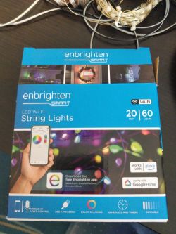
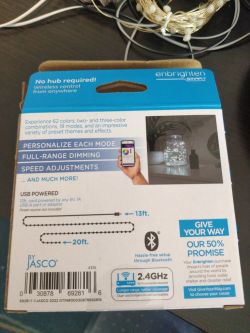
    Box of Enbrighten Smart LED Wi-Fi String Lights on a table.Image of the packaging for Enbrighten Smart LED Wi-Fi String Lights, model 69281 v1, with visible technical specifications.

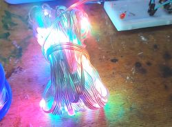
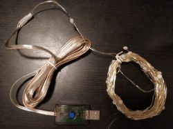
    You can just barely see the actual light part of it in the upper right corner of the first image; it's three bare-looking (but presumably somehow insulated) wires with little plastic blobs along them every so often holding the actual LEDs, collectively outputting about no lumens. Not sure it was worth the $5 I paid for it on clearance.

    It acts a lot like the WFD4105E smart plug I posted about previously: it has one button, and a fast flashing blue mode and a slow flashing blue mode, and in the slow flashing blue mode it puts up a WiFi access point.

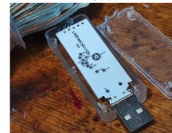
    Here's the control box. Note that the whole thing is USB-powered.
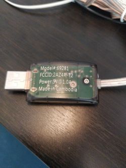
    Photo of Enbrighten Smart LED Wi-Fi String Lights controller, model 69281.

    I managed to get the case open by removing the one little Torx screw that holds it closed, and here are some photos of the board layout.
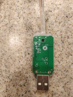
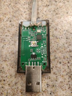
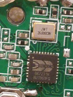
    Close-up of a PCB board with visible pins and USB connection.PCB layout of a controller powered by USB.Close-up of a circuit board featuring a Beken BK2731N chip and electronic components.

    It appears to have a BK2731N in there, as well as test points for not one but two UARTs. The USB data pins sadly don't go anywhere. I guess it was too much to hope for that they would spring for an FTDI chip.

    The packaging is copyright 2022, so I'm not sure if it has a vulnerable or patched Tuya firmware on it (or any Tuya firmware, since there's no separate Tuya module) for wireless flashing. I also haven't flashed it via UART yet (which I think might be the best way to get the config info for the lights and the button?); I'll need to do some research to find out how that all works.
  • ADVERTISEMENT
  • Helpful post
    #2 21226433
    p.kaczmarek2
    Moderator Smart Home
    This device is most likely using WS2812B or similiar per-pixel indexable LEDs. It should work good with PixelAnim driver:
    https://www.elektroda.com/rtvforum/topic4057187.html
    This means that most likely P16 (SPI data out) of Beken chip is used to control LEDs data line. Futhermore LEDs are getting GND and VDD (5V) lines, so there are 3 wires coming to LEDs.
    You also have one button on the board, which can be configured to use Btn_SmartLED role in OBK.

    I've been actually testing somewhat similiar USB-powered device last month and it worked good with OBK:
    Bundle of WS2812B LEDs emitting multicolored light. Electronic module with a USB connector on a wooden table.
    So, take 2MB backup and you can try to flash. I assume you've seen our flashing guides?
    https://www.youtube.com/@elektrodacom
    Wireless flashing is problematic and not reliable so I wouldn't bother trying it as long as you have some basic soldering equipment.

    As for USB pins, they don't intend for us to use it for any communication so they are not connected.
    Helpful post? Buy me a coffee.
  • ADVERTISEMENT
  • #3 21226746
    interfect
    Level 4  
    Thanks! You were right about the setup; the PixelAnim driver works great! It even presents mostly properly to HomeAssistant.

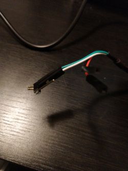
    To get a UART connection, I took a short length of pin header (3 pins was as short as I could break off), bent the pins on one side to be closer together and then up out of the plane of the header, attached the USB to UART cable RX and TX leads to the other side of the header, and electrical taped it to the board to make contact with the TX1 and RX1 pads (respectively). The bending out of the plane was important; I had no luck just electrical-taping the pin header pins onto the pads. Here's the highly advanced interface cable I ended up with:

    Interface cable with connected USB to UART wires.

    I wasn't having much luck with the GUI flasher on Mono because of what looks like a Mono-related bug on the read side, so I did a 2 MiB flash dump with the old hid_download_py uartprogram tool:

    ./uartprogram firmware.bin -d /dev/ttyUSB0 -r -u -s 0x0 -l 0x200000


    Here's the firmware file, in case that is useful for maybe making wireless flashing work, or determining that it can't:
    firmware...iB.bin Download (2 MB)

    The downloader tool gave me a CRC failure no matter what I did. But I dumped the file twice at two different baud rates and got the same file. Also I put that file into the GUI flasher to try and extract a config and I got what looked like plausible output:

    
    {
       "rstnum":"10",
       "rstcor":"b",
       "Jsonver":"1.0.0",
       "gmwb":"40",
       "title20":"0",
       "key1_pin":"20",
       "gmwg":"40",
       "knum":"1",
       "wfcfg":"spcl_auto",
       "colormin":"10",
       "miso":"17",
       "mosi":"16",
       "pmemory":"1",
       "gmkb":"65",
       "k1sfunc":"5",
       "keyfunc":"1",
       "irfunc":"0",
       "cmod":"rgb",
       "lednum":"60",
       "netlptime":"5",
       "strsep":"10",
       "MISO":"17",
       "rstbr":"80",
       "key1_lv":"0",
       "brightstep":"20",
       "remdmode":"0",
       "colormax":"50",
       "module":"CBU",
       "colorpfun":"1",
       "rstmode":"1",
       "CS":"15",
       "k1lfunc":"1",
       "dmod":"0",
       "gmwr":"40",
       "colormaxp":"100",
       "gmkg":"65",
       "onoffmode":"1",
       "colororder":"0",
       "speedstep":"20",
       "wfct":"3",
       "brightrate":"20",
       "lptime":"3",
       "aging":"0",
       "category":"1101",
       "SCL":"14",
       "gmkr":"65",
       "defcolor":"r",
       "defbright":"80",
       "crc":"102"
    }


    Device configuration, as extracted from Tuya: 
    - SPI MISO 17
    - SPI MOSI 16
    Device seems to be using CBU module, which is using BK7231N.
    And the Tuya section starts, as usual, at 2023424


    The OpenBeken Configuration Generator didn't seem to be able to bet much out of that, though (I guess it expects a different JSON format?). But from
    "key1_pin":"20",
    you can tell that pin 20 is where the button is on this device.

    I flashed
    OpenBK7231N_QIO_1.17.697.bin
    with the GUI flasher, with my WiFi settings pre-populated, and the device came up and works great! The PixelAnim tutorial you linked wanted me to use LittleFS and autoexec.bat, but I managed to fit the necessary script into the startup command's 512 bytes as:

    backlog startDriver SM16703P; SM16703P_Init 60; startDriver PixelAnim


    And then since I am using HomeAssistant I added another
    ; scheduleHADiscovery 5
    at the end.

    The "Btn_SmartLED" feature is nice; I can change color with a double-press and brightness with a long press.

    So my draft of the device template would be:
    
    {
      "vendor": "Enbrighten",
      "bDetailed": "0",
      "name": "Enbrighten Smart LED Wi-Fi String Lights 69281 v1",
      "model": "69281",
      "chip": "BK7231N",
      "board": "CBU",
      "flags": "0",
      "keywords": [
        "RGB",
        "LED String",
        "SM16703P"
      ],
      "pins": {
        "20": "Btn_SmartLED;0"
      },
      "command": "backlog startDriver SM16703P; SM16703P_Init 60; startDriver PixelAnim",
      "image": "https://obrazki.elektroda.pl/5988475600_1726356778.jpg",
      "wiki": "https://www.elektroda.com/rtvforum/topic4075705.html"
    }


    Here's a better photo of the whole device (for the template).
    LED string lights with USB plug and control button.
  • ADVERTISEMENT
  • #5 21420436
    interfect
    Level 4  
    The forum emailed me to come back and close this topic. My device has been working pretty well ever since I flashed it, and I finally found an actual use for it.
ADVERTISEMENT