Generic Tuya WiFi Smart Switches (bare minimum BK7231N)
I bought these on aliexpress because of their price (the cheapest I could find). These are built down to price and have no modules in them, just a BK7231N on the main board.

WiFi only: https://www.aliexpress.us/item/3256806781135781.html
WiFi + RF 433 MHz: https://www.aliexpress.us/item/3256806984455025.html
I looked for the cheapest ones because my goal is not to use them as is, but rather re-flash them to my liking and use in my home assistant setup.
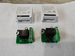
Let's crack them open! There is just a single board inside. Terminals, relay and power supply inductor/capacitors on one side (+antenna for RF version):
and all other electronics including BK7231N, power supply chips, and other discrete components (RF version also has what seems to be a SYN470R receiver chip) on the other side:
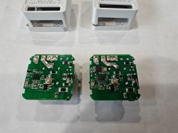
Not sure about the receiver - it is an unmarked chip, but connections seem to match the 8-pin package pinout in the datasheet. Exact model of receiver chip is not important though. So let's find out how to reprogram these boards. I used a multimeter with really thin and sharp probes to probe BK chip pads directly and found out all the required connection points and where peripherals connected to.
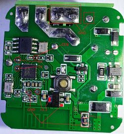
There are very conveniently placed test pads for CEN, RX and TX pins. They are easily accessible to solder with a soldering iron.
There are also pads for GND and +3.3, but they are not so conveniently located - there are other components nearby. However, it is a blessing in disguise as this board has a 3.3 volt regulator, so we can power it from USB directly! Just solder 2 wires on each side of 2K resistor and we are golden.
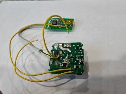
2 middle pins of the main connector form a large unmasked surface which is connected to ground. That makes it a perfect point to touch with a wire soldered to CEN pad to initiate chip reprogramming.
Peripheral connections:
Relay is connected to P7
Button is connected to P23
LED is connected to P26
External switch (main terminals) shorts P6 to ground
RF receiver is on P8 (on the WiFi+RF board only)
I will not dive deep into programming details, there are already enough detailed articles and videos on the internet on this topic. Just a brief instructions.
If you want to go with OpenBK firmware, then:
1. Download the latest BK7231 Flash Tool: https://github.com/openshwprojects/BK7231GUIFlashTool
2. Run it and click on the "Download latest from the web" button.
3. Select the right COM-port for your USB-Serial adapter
4. Select BK7231N chip
5. Click the "Do backup and flash new" button, short the CEN to GND momentarily and the flashing process will begin.
It should extract the template and pin mapping just fine except the RF pin. My template:
6. Go to your router, discover the IP address of your newly flashed module, go to http://<device_ip> and finish the setup by clicking on Config button. From the config menu go to Configure Module if you want to reconfigure pins. I personally found WiFiLED_n useless, so I changed it to LED_n with channel 1. I plan to 3D print a switch housing, so LED_n will light up when the switch is off, making it easier to find in the dark.
Finally, on the Configure MQTT page put the address and user/password to connect to your MQTT broker and the most basic setup is done.
This is an easy way and works beautifully for the WiFi version of the switch (no RF). I wasn't able to figure out how to configure RF. Apparently it needs some scripts, starting a driver, etc. Not so easy anymore. Also my end goal is to use it with Home Assistant, so I decided to go another way and install the EspHome firmware.
If you want to go with EspHome firmware, then:
1. Install the EspHome command line. I think it is possible to do using the Home Assistant GUI, but the process is not straightforward.
2. Install the LibreTiny platform by executing the command:
3. Create a .yaml config file for the device. Here are my configs as an example:
WiFi switch
WiFi+RF switch
These are basically the same configs, the only difference is the remote_receiver and the corresponding binary_sensor for RF version.
Here again I used the LED to reflect the status of the switch. If you want to use it as a status LED, uncomment the status_led section and remove internal_led output and associated actions.
4. Execute the command to compile the firmware:
This should generate the source code for your device and compile it into firmware.
5. Download the ltchiptool program to flash the board: https://github.com/libretiny-eu/ltchiptool/releases/latest and run it.
6. [Optional] Let's back up the chip flash just in case. In the flasher GUI select the COM-port and choose the Read flash option. Select the output file, select the "Beken 72xx" chip family and click Start. It will begin the backup process. Don't forget to short CEN to ground to initiate the communication with the chip. Be patient it takes quite a few minutes to complete.
7. Let's flash it! In the flasher GUI select the COM-port and choose the Write flash option. Select the input file (mine is located in the <yaml folder>\.esphome\build\upk2esphome-bk7231n\.pioenvs\upk2esphome-bk7231n\firmware.uf2), select the "Beken 72xx" chip family and click Start. It will begin the flashing process. Don't forget to short CEN to ground to initiate the communication with the chip.
8. You are done. Now go to Home Assistant, discover the new EspHome device and add it. No need to setup MQTT.
A quick note on how to "learn" the remote button code. I identified the remote button that came with the device to be of rc_switch family. If you use a different remote, please select the proper type. Uncomment the dump section of the remote_receiver. Recompile and flash the firmware. Since logging goes through UART2 by default, we can't use that. Instead we have the web_server section in the config. This allows us to navigate to the device through the browser. So go grab the IP address from your router and go to http://<device_ip> page. There you will see the log output on the right. Press the button and it should dump the received code. Now put your code in the yaml config, recompile and reflash it.
Good luck!
I bought these on aliexpress because of their price (the cheapest I could find). These are built down to price and have no modules in them, just a BK7231N on the main board.

WiFi only: https://www.aliexpress.us/item/3256806781135781.html
WiFi + RF 433 MHz: https://www.aliexpress.us/item/3256806984455025.html
I looked for the cheapest ones because my goal is not to use them as is, but rather re-flash them to my liking and use in my home assistant setup.
Let's crack them open! There is just a single board inside. Terminals, relay and power supply inductor/capacitors on one side (+antenna for RF version):

and all other electronics including BK7231N, power supply chips, and other discrete components (RF version also has what seems to be a SYN470R receiver chip) on the other side:

Not sure about the receiver - it is an unmarked chip, but connections seem to match the 8-pin package pinout in the datasheet. Exact model of receiver chip is not important though. So let's find out how to reprogram these boards. I used a multimeter with really thin and sharp probes to probe BK chip pads directly and found out all the required connection points and where peripherals connected to.

There are very conveniently placed test pads for CEN, RX and TX pins. They are easily accessible to solder with a soldering iron.
There are also pads for GND and +3.3, but they are not so conveniently located - there are other components nearby. However, it is a blessing in disguise as this board has a 3.3 volt regulator, so we can power it from USB directly! Just solder 2 wires on each side of 2K resistor and we are golden.

2 middle pins of the main connector form a large unmasked surface which is connected to ground. That makes it a perfect point to touch with a wire soldered to CEN pad to initiate chip reprogramming.
Peripheral connections:
Relay is connected to P7
Button is connected to P23
LED is connected to P26
External switch (main terminals) shorts P6 to ground
RF receiver is on P8 (on the WiFi+RF board only)
I will not dive deep into programming details, there are already enough detailed articles and videos on the internet on this topic. Just a brief instructions.
If you want to go with OpenBK firmware, then:
1. Download the latest BK7231 Flash Tool: https://github.com/openshwprojects/BK7231GUIFlashTool
2. Run it and click on the "Download latest from the web" button.
3. Select the right COM-port for your USB-Serial adapter
4. Select BK7231N chip
5. Click the "Do backup and flash new" button, short the CEN to GND momentarily and the flashing process will begin.
It should extract the template and pin mapping just fine except the RF pin. My template:
Spoiler:
{
"vendor": "Tuya",
"bDetailed": "0",
"name": "Full Device Name Here",
"model": "enter short model name here",
"chip": "BK7231N",
"board": "TODO",
"flags": "0",
"keywords": [
"TODO",
"TODO",
"TODO"
],
"pins": {
"6": "TglChanOnTgl;1",
"7": "Rel;1",
"23": "Btn_Tgl_All;0",
"26": "WifiLED_n;0"
},
"command": "",
"image": "https://obrazki.elektroda.pl/YOUR_IMAGE.jpg",
"wiki": "https://www.elektroda.com/rtvforum/topic_YOUR_TOPIC.html"
}
6. Go to your router, discover the IP address of your newly flashed module, go to http://<device_ip> and finish the setup by clicking on Config button. From the config menu go to Configure Module if you want to reconfigure pins. I personally found WiFiLED_n useless, so I changed it to LED_n with channel 1. I plan to 3D print a switch housing, so LED_n will light up when the switch is off, making it easier to find in the dark.
Finally, on the Configure MQTT page put the address and user/password to connect to your MQTT broker and the most basic setup is done.
This is an easy way and works beautifully for the WiFi version of the switch (no RF). I wasn't able to figure out how to configure RF. Apparently it needs some scripts, starting a driver, etc. Not so easy anymore. Also my end goal is to use it with Home Assistant, so I decided to go another way and install the EspHome firmware.
If you want to go with EspHome firmware, then:
1. Install the EspHome command line. I think it is possible to do using the Home Assistant GUI, but the process is not straightforward.
2. Install the LibreTiny platform by executing the command:
pio pkg install --platform libretiny3. Create a .yaml config file for the device. Here are my configs as an example:
WiFi switch
Spoiler:
esphome:
  name: esphome-bk7231n

bk72xx:
  board: generic-bk7231n-qfn32-tuya

web_server:

captive_portal:

mdns:

api:
  password: ""

#ota:

wifi:
  ssid: your_wifi
  password: your_password

text_sensor:
  - platform: libretiny
    version:
      name: LibreTiny Version

binary_sensor:
  - platform: gpio
    id: binary_onoff_1
    pin:
      number: P6
      inverted: true
      mode: INPUT_PULLUP
    on_state:
      then:
        - switch.toggle: switch_1
  - platform: gpio
    id: binary_switch_all
    pin:
      number: P23
      inverted: true
      mode: INPUT_PULLUP
    on_press:
      then:
        - switch.toggle: switch_1

switch:
  - platform: gpio
    id: switch_1
    name: Relay 1
    pin: P7
    on_turn_on:
      then:
        - output.turn_off: internal_led
    on_turn_off:
      then:
        - output.turn_on: internal_led

output:
  - platform: gpio
    id: internal_led
    pin: P26

#status_led:
#  pin:
#    number: P26
#    inverted: true
WiFi+RF switch
Spoiler:
esphome:
  name: esphome-bk7231n

bk72xx:
  board: generic-bk7231n-qfn32-tuya

web_server:

captive_portal:

mdns:

api:
  password: ""

#ota:

wifi:
  ssid: your_wifi
  password: your_password

text_sensor:
  - platform: libretiny
    version:
      name: LibreTiny Version

binary_sensor:
  - platform: gpio
    id: binary_onoff_1
    pin:
      number: P6
      inverted: true
      mode: INPUT_PULLUP
    on_state:
      then:
        - switch.toggle: switch_1
  - platform: gpio
    id: binary_switch_all
    pin:
      number: P23
      inverted: true
      mode: INPUT_PULLUP
    on_press:
      then:
        - switch.toggle: switch_1
  - platform: remote_receiver
    id: remote_button
    rc_switch_raw:
      code: "100011011100000001101000"
    filters:
      - settle: 250ms
    on_press:
      then:
        - switch.toggle: switch_1

switch:
  - platform: gpio
    id: switch_1
    name: Relay 1
    pin: P7
    on_turn_on:
      then:
        - output.turn_off: internal_led
    on_turn_off:
      then:
        - output.turn_on: internal_led

output:
  - platform: gpio
    id: internal_led
    pin: P26

#status_led:
#  pin:
#    number: P26
#    inverted: true

remote_receiver:
  pin:
    number: P8
    inverted: false
    mode: INPUT_PULLUP
#  dump:
#    - rc_switch
  tolerance: 25%
  filter: 250us
  idle: 5ms
  buffer_size: 2kB
These are basically the same configs, the only difference is the remote_receiver and the corresponding binary_sensor for RF version.
Here again I used the LED to reflect the status of the switch. If you want to use it as a status LED, uncomment the status_led section and remove internal_led output and associated actions.
4. Execute the command to compile the firmware:
epshome compile the_name_of_your_config_file.yamlThis should generate the source code for your device and compile it into firmware.
5. Download the ltchiptool program to flash the board: https://github.com/libretiny-eu/ltchiptool/releases/latest and run it.
6. [Optional] Let's back up the chip flash just in case. In the flasher GUI select the COM-port and choose the Read flash option. Select the output file, select the "Beken 72xx" chip family and click Start. It will begin the backup process. Don't forget to short CEN to ground to initiate the communication with the chip. Be patient it takes quite a few minutes to complete.
7. Let's flash it! In the flasher GUI select the COM-port and choose the Write flash option. Select the input file (mine is located in the <yaml folder>\.esphome\build\upk2esphome-bk7231n\.pioenvs\upk2esphome-bk7231n\firmware.uf2), select the "Beken 72xx" chip family and click Start. It will begin the flashing process. Don't forget to short CEN to ground to initiate the communication with the chip.
8. You are done. Now go to Home Assistant, discover the new EspHome device and add it. No need to setup MQTT.
A quick note on how to "learn" the remote button code. I identified the remote button that came with the device to be of rc_switch family. If you use a different remote, please select the proper type. Uncomment the dump section of the remote_receiver. Recompile and flash the firmware. Since logging goes through UART2 by default, we can't use that. Instead we have the web_server section in the config. This allows us to navigate to the device through the browser. So go grab the IP address from your router and go to http://<device_ip> page. There you will see the log output on the right. Press the button and it should dump the received code. Now put your code in the yaml config, recompile and reflash it.
Good luck!


