I've been playing with a KMC Smart Tap Mini, Model 30407 (here's the Amazon link).
@mjspez posted a teardown in this forum back in Feb 2023 in which they desoldered the CB2S module and flashed it with OpenBK. That thread pivoted to a bunch of work by @omniron as they worked on getting cloudcutter working with it.
There was also work by @starfoxinstinct on a cloudcutter template for it here.
I'm looking for a long term supply of parts that work, so depending on cloudcutter (which is, or will be, patched) isn't a great option. I'd also rather not desolder modules on a regular basis.
To that end, I whipped up a little 3d-printed jig that positions pogo pins over the module contacts and started trying to get ltchiptool to talk to it. After a lot of failures, I noticed a couple of things:
- I could get the Smartlife AP to appear by pushing the button.
- The center LED, and/or one of the relays, would often click when ltchiptool was running if I tried it while the factory firmware was running.
This, various multimeter poking and prodding, and re-reading the pin assignments from @mjspez' writeup made me realize that the TX/RX pins on the module are being used in their GPIO guise when the factory firmware is running. I think that the physical connections associated with this are preventing them from being used as TX/RX while trying to run ltchiptool.
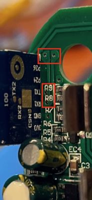
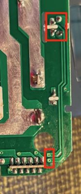
The two pins seem to come out to traces from the back to the front of the board right near the R8/R9 labels in the first photo, then run up towards the corner of the board. From there they duck back through the board to a pair of traces on the back of the board that run to the button and LED. I've verified this with the continuity tester on my multimeter.


I'm not sure I'm up for the adventure, but if I were to cut those traces, would that allow ltchiptool to run? Would I then be able to reconnect the trace? Any suggestions/techniques for this would be welcome.
In the meantime, I'm going to see if this unit is vulnerable to the cloudcutter vulnerability.
@mjspez posted a teardown in this forum back in Feb 2023 in which they desoldered the CB2S module and flashed it with OpenBK. That thread pivoted to a bunch of work by @omniron as they worked on getting cloudcutter working with it.
There was also work by @starfoxinstinct on a cloudcutter template for it here.
I'm looking for a long term supply of parts that work, so depending on cloudcutter (which is, or will be, patched) isn't a great option. I'd also rather not desolder modules on a regular basis.
To that end, I whipped up a little 3d-printed jig that positions pogo pins over the module contacts and started trying to get ltchiptool to talk to it. After a lot of failures, I noticed a couple of things:
- I could get the Smartlife AP to appear by pushing the button.
- The center LED, and/or one of the relays, would often click when ltchiptool was running if I tried it while the factory firmware was running.
This, various multimeter poking and prodding, and re-reading the pin assignments from @mjspez' writeup made me realize that the TX/RX pins on the module are being used in their GPIO guise when the factory firmware is running. I think that the physical connections associated with this are preventing them from being used as TX/RX while trying to run ltchiptool.
The two pins seem to come out to traces from the back to the front of the board right near the R8/R9 labels in the first photo, then run up towards the corner of the board. From there they duck back through the board to a pair of traces on the back of the board that run to the button and LED. I've verified this with the continuity tester on my multimeter.


I'm not sure I'm up for the adventure, but if I were to cut those traces, would that allow ltchiptool to run? Would I then be able to reconnect the trace? Any suggestions/techniques for this would be welcome.
In the meantime, I'm going to see if this unit is vulnerable to the cloudcutter vulnerability.


