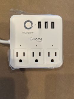
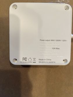
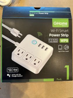
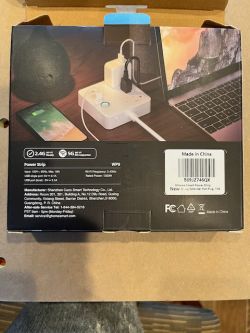
I bought a GHome WP9 on Amazon.
Things to like about it include:
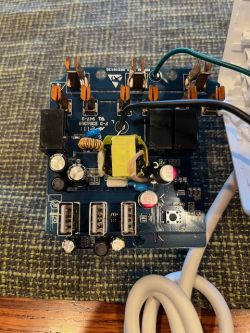
- It has a relay for the USB switches, though they're controlled as a unit.
- It's compact, though this means large plugs will be a problem.
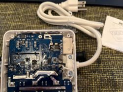
- It's easy to open (2.3mm triangle head screwdriver, suction cup).
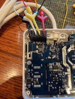
- It presents nice, big, accessible pads for v3.3, GND, RX and TX on the edge of the circuit board when you remove the back.
Things to not like about it:
- It's only rated to 10A.
- I wish the cord had a flat plug.
Other things to know about it:
- It uses a Z2-N-V1.1 module.
- That module contains:
There's a forum post about flashing OpenBK via cloudcutter, but that no longer works (discovered empirically, confirmed by examining the stock software).
I whipped up a 3d-printed pogo pin jig to keep things simple, shared:
- here on Thingiverse; and
- here on Printables.
Both include the CadQuery source code, an STL file, the `.bgcode` for my Prusa Mini, and a link to the pogo pins I used.
Flashing was easy:
- Position the jig and hold it firmly.
- Insert USB UART into laptop.
- Run `ltchiptool -v flash write ./OpenBK7231N_QIO_1.17.739.bin`
- Wait until `ltchiptool` prompts for a reset, then disconnect the power lead, wait a second, then reconnect it.
- Wait patiently for the upload to finish.
Here's the config that I ended up with.
There's also an LED on pin 8, but if I try to set is as an LED it messes with the one on pin 7. I'm confused...
Note: The Tasmota device page for this device warns about reversed polarity on middle and right plugs. All of the plugs on my device pass muster with my little plug-in circuit tester.


Things to like about it include:
- It has a relay for the USB switches, though they're controlled as a unit.
- It's compact, though this means large plugs will be a problem.
- It's easy to open (2.3mm triangle head screwdriver, suction cup).
- It presents nice, big, accessible pads for v3.3, GND, RX and TX on the edge of the circuit board when you remove the back.
Things to not like about it:
- It's only rated to 10A.
- I wish the cord had a flat plug.
Other things to know about it:
- It uses a Z2-N-V1.1 module.
- That module contains:
Code: Text
There's a forum post about flashing OpenBK via cloudcutter, but that no longer works (discovered empirically, confirmed by examining the stock software).
I whipped up a 3d-printed pogo pin jig to keep things simple, shared:
- here on Thingiverse; and
- here on Printables.
Both include the CadQuery source code, an STL file, the `.bgcode` for my Prusa Mini, and a link to the pogo pins I used.
Flashing was easy:
- Position the jig and hold it firmly.
- Insert USB UART into laptop.
- Run `ltchiptool -v flash write ./OpenBK7231N_QIO_1.17.739.bin`
- Wait until `ltchiptool` prompts for a reset, then disconnect the power lead, wait a second, then reconnect it.
- Wait patiently for the upload to finish.
Here's the config that I ended up with.
Code: JSON
There's also an LED on pin 8, but if I try to set is as an LED it messes with the one on pin 7. I'm confused...
Note: The Tasmota device page for this device warns about reversed polarity on middle and right plugs. All of the plugs on my device pass muster with my little plug-in circuit tester.


