logo elektroda
logo elektroda
X
logo elektroda

Monitor for retro computer based on laptop matrix and RTD2660 module

andreyatakum 4092 37
ADVERTISEMENT
Treść została przetłumaczona polish » english Zobacz oryginalną wersję tematu
  • Retro computers have become very popular in recent times. Prices for such devices range from not too old cars. Manufacturers have not missed the opportunity and offer various types of clones. They are much cheaper, but they do not give the same satisfaction and note of nostalgia as the original computers, which recall the first impressions of dealing with a modern (for those times) curiosity.

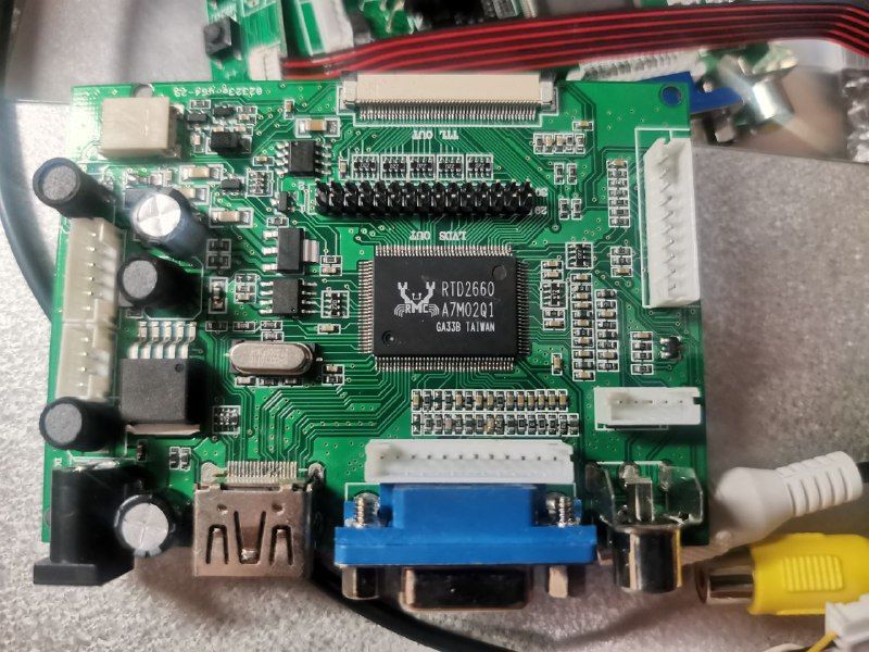
    PCB with RTD2660 chip and video ports
    .

    Retro hardware: building a dedicated monitor .
    However, a problem arises - the display. Old home computers were designed to connect to CRT and low-resolution televisions running PAL/NTSC/SECAM colour systems. Few people still keep these giants in their homes. Modern TVs have long used HDMI-type connectors for input. SCART and RCA connectors have become a thing of the past. It is very rare to find VGA-type connectors anymore. This type of connection is best suited to old computers with RGB output. Admittedly, there is no separate sync signal, but this problem is relatively easy to solve. Unfortunately, this does not always work - modern TVs and monitors do not accept low-resolution video signals.

    In my opinion, the best solution to this issue may be to build your own monitor, using a used matrix from a laptop or tablet and a cheap universal PCB800099 module based on the RTD2660 chip. Its advantage, unlike others, including those described on the pages of our portal, is that changes can be made to the software, i.e. the code. The prices of these boards on AliExpress do not exceed PLN 25. You need to add the appropriate tape, connecting it to the matrix, and buttons. Details of how to connect the controllers to the matrices are described in our forum under this link . The physical connection of the IC should not be problematic for a more or less experienced electronics technician.

    Modifying the software using the Arduino .
    As for adapting the code to the matrix, at first glance this may appear to be a cumbersome affair. However, it only looks that way.
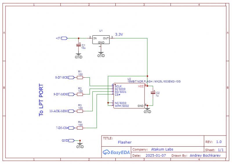
    A property of the controllers, based on the RTD2660 processor, is that the control code is on a 25x40 EPROM memory chip. So we need a SPI programmer for these cubes. It can be any one you like. You can even use the parallel port of an old computer. Schematic below.

    I have neither a specialised programmer nor a serial port. I used an Arduino. There is a lot of information about programming an SPI device using it, including on our forum.
    You can connect the chip to the programmer using wires, no soldering is necessary. You just need to connect the ground and the 3.3 V supply. I don't recommend using long wires, because interference can cause errors. First, using the programmer, we read out the already recorded code and save it on the hard disk (or pendrive) just in case.
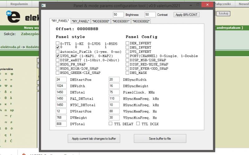
    Next we run the programme: "Control code configuration". This was developed thanks to a ZX-PK forum member named Valerim. He managed to find the code sections that are responsible for the resolution and the image location. The configuration programme makes it easy to make changes to the code without having to search for the relevant parameters there.. We open the file with the one read earlier and modify it according to the characteristics of the matrix and our own requirements.

    Panel and mode parameter configuration software
    .
    Tile code control panel.


    Basic configuration .
    In the first case, everything is clear. We look in the Datasheet and set the resolution according to it in the "My panel" menu. There this valence is marked twice, so we enter it twice. After the change, we press the "Apply current tab changes to buffer" button.
    After correcting the matrix indicators (if the need arises at all), we go to the "MODE000x" menu. There, we change the three qualities - needed vertical resolution, horizontal resolution and frequency - according to these computer factors. If you want to get the best image quality from your computer on a matrix with a high resolution, you should select a number higher than the original. For example, the ZX-Spectrum produces a video signal with a resolution of 768х288, in which case a better result can be obtained by fixing 1536x576. Provided, of course, that the matrix allows this, i.e. has a higher resolution.

    After making all the changes in both menus, we press "APPLY BRI/COUNT". With this program we can also determine the brightness and contrast (with the sliders at the top). However, the exact values can only be determined after the monitor has been switched on for the first time. Before this, the modified file is uploaded (using the programmer software!) to the EPROM memory cube, the programmer is disconnected from the board, the buttons and power supply are connected. The image may not be exactly in the centre of the screen. This can be corrected using the controller menu. However, this operation is not always successful. In this case, disconnect the power supply, plug in the programmer, and determine the new image location values. Then upload the new file and repeat the steps.

    The best result may not be obtained immediately, so I recommend connecting the wires to the memory cube via any MF connector.
    Attached you will find an archive with the configuration program and an example code file. There is also a program for the simplest serial port programmer in the "Programs" folder, but it only works with the DOS operating system (can be downloaded from the web and run from a flash drive).


    DOS-LPT programmer schematic with ICs and connections.
    .
    Schematic programmer via DOS-LPT.

    Cool? Ranking DIY
    Do you have a problem with Arduino? Ask question. Visit our forum Arduino.
    About Author
    andreyatakum
    Level 14  
    Offline 
    andreyatakum wrote 558 posts with rating 782. Live in city Antalya. Been with us since 2021 year.
  • ADVERTISEMENT
  • #2 21390430
    LightOfWinter
    Level 38  
    andreyatakum wrote:
    The old home computers were designed to connect to CRT and low-resolution televisions running PAL/NTSC/SECAM colour systems. Few people still keep these giants in their homes.
    .
    This sounds very nice, but it is not true. There are quite a few newer flat screen monitors/TVs that have a rich palette of inputs. So you can plug in without a problem.

    andreyatakum wrote:
    Modern TVs have long used HDMI type connectors for input. SCART and RCA connectors have become a thing of the past.
    They have not gone away they can be found even in Smart TVs :) .
    Sometimes an adapter supplied by the manufacturer is needed.

    Nevertheless nice device and good description :) Thanks!
  • #3 21391045
    Atos30
    Level 14  
    LightOfWinter wrote:
    They have not gone away they can be found even on Smart TVs.
    Sometimes you need an adapter supplied by the manufacturer.


    Please give examples from several manufacturers of new Smart TVs with such connectors.
  • #4 21391345
    DJ MHz
    Level 25  
    Sony Bravia of 2022 with Android TV.
  • #5 21391370
    Atos30
    Level 14  
    >>21391345 .
    Which model? And overall, it's 2025.
  • #6 21391431
    andreyatakum
    Level 14  
    LightOfWinter wrote:
    there are quite a few newer flat screen monitors/TVs that have a rich palette of inputs. So you can plug in without a problem.
    .
    But they don't always work properly. E.g. Only one of my three monitors works with the HDMI-VGA adapter.
  • #7 21391902
    LightOfWinter
    Level 38  
    Atos30 wrote:
    Which model? And generally this is 2025
    .
    E.g. Samsung UE40D5500 and similar to it. How they work I have not checked. There was no need to.

    andreyatakum wrote:
    But they don't always work properly. E.g. only one of my three monitors works with the HDMI-VGA adapter.
    .

    You do not need an adapter. You can buy an EIZO EV2450 for example and the VGA port is built in.
    https://amso.pl/product-pol-84900-Cienkoramko...n-EV2450-24-IPS-1920x1080-LED-HDMI-Bialy.html
    (There are cheaper offers :) )
    There are also Samsung and NEC monitors richly equipped with ports.
  • ADVERTISEMENT
  • #8 21391915
    andreyatakum
    Level 14  
    LightOfWinter wrote:
    There are also Samsung and NEC monitors richly equipped with ports.

    And how much does it cost compared to the matrix and the RTD2660 module? Is there any assurance that it can work with a retrocomputer?
  • #9 21391920
    LightOfWinter
    Level 38  
    andreyatakum wrote:
    LightOfWinter wrote:
    There are also monitors from Samsung and NEC richly equipped with ports.

    How much does it cost compared to a matrix and RTD2660 module? Is there any assurance that it can work with a retrocomputer?


    In terms of cost, it costs me 0 PLN because I have several 24" monitors with VGA inputs.

    It is difficult to answer whether it will work with a retro computer because I do not know what exactly you mean by a retro computer. Is it a machine that is 5, 10, 20 years old or even older. But you can look in the specifications for what VGA modes are supported.

    https://www.eizoglobal.com/support/db/files/manuals/03V25129G1/UM-03V25129G1-EN.pdf

    It supports resolutions from 640x480.
  • #10 21392264
    Anonymous
    Level 1  
  • #11 21392445
    gregor124
    Level 26  
    LightOfWinter wrote:
    It's difficult to answer if it will work with a retro computer because I don't know what exactly you mean by a retro computer. Is it a machine that is 5, 10, 20 years old or even older. But you can look in the specification what VGA modes are supported.
    .
    It's not that difficult at all, and I can already tell you that it will NOT work with the graphic modes that were used so more or less until the end of the 1980s. And the problem is not the socket type at all, because VGA cards could display and probably still can today display MDA, CGA, EGA modes etc.
    And because the lowest horizontal frequency that this monitor supports is 31 kHz, while 15 kHz was common at the time.

    But even then such monitors were not common, and if they were, such as the old NEC Multisync, they were b. expensive.
    It was common practice to use 2 different monitors 31kHz and 15kHz.
  • #12 21392514
    LightOfWinter
    Level 38  
    gregor124 wrote:
    It's not that difficult at all, and I can already hint to you that it will NOT work with the graphic modes that were used so more or less until the end of the 80s.
    .

    I understand. Nevertheless, it is not a problem for me because I do not have such equipment and do not use it.
  • #13 21392653
    DJ MHz
    Level 25  
    Atos30 wrote:
    >>21391345 .
    Which model? And in general it is the 2025.


    And in general, make up your mind. You're asking about the new ones with tv grease and a connector is what I specified. The same newer bravas also have connectors out + adapter :D .
  • ADVERTISEMENT
  • #14 21394956
    decho
    Level 14  
    >>21392653 Without bragging , I recently bought a Philips 20" flat screen for 80£. It has antenna inputs TV, sCART, VGA, HDMI, Composit or whatever it is called there and RCA? (Video+L+R). I don't think it only has DP. And it works great as a tester for all sorts of PS1, xbox 360 etc.
    Nevertheless I am still tempted to build this monitor according to your description, just for my own satisfaction and fun.
    Super description, Congratulations and thanks for sharing your knowledge.
  • #15 21395658
    kmr
    Level 18  
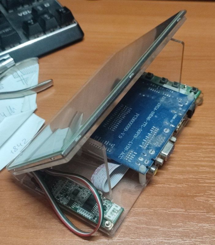
    Do you have any photos of the finished product i.e. the Retro Monitor or is it just a display matrix?
  • #16 21395822
    andreyatakum
    Level 14  
    >>21395658 .

    Electronic kit with display and circuit board on a desk.
    .

    Interesting, but no one has pointed out that this universal tile by the preprogramming I recommended allows you to place the image anywhere and even reduce the border on the ZX Spectrum.
  • #17 21396931
    puchalak
    Level 17  
    At the moment, building such a monitor is pointless. You can have plenty of these on a popular auction site for a nominal fee. Just like older TVs that do not receive DVBT2 with a whole range of inputs.
    I myself recently gave away a couple of working monitors for electro-waste only because they were useless without hdmi or dvi.
  • #18 21397230
    xangel
    Level 19  
    The post is from 2025 but I see these interfaces on Ali for a minimum of £59.

    On allegro you have a Dell U2410f (e.g. auction 17131151671) without the cradle for 70zł. See what sockets it has, your eyes will pop out :) .
  • #19 21397365
    andreyatakum
    Level 14  
    xangel wrote:
    Post is from 2025 but I see these interfaces on Ali for a minimum of £59.
    .


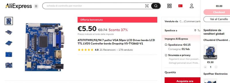
    Screenshot of an AliExpress offer featuring an LCD controller board.
    .

    Added after 1 [minute]:

    xangel wrote:
    The post is from 2025 but I see these interfaces on Ali for a minimum of £59.


    A couple of months ago it was €4.5
  • #20 21397377
    xangel
    Level 19  
    I typed in PCB800099 and it has different prices, but all in all a module is a module.
    But it jumps you a 37% discount there
    Are you logged in? Because often these prices are just decoys and then when you log in the price is different.
    Give the auction number
  • ADVERTISEMENT
  • #21 21423231
    salacpavel
    Level 2  
    Hello Andrey, I came across this post when looking for 15kHz solution to replace aging CRT in my legacy machinery. Once I bought a set of RTD2660 controller and LCD from Aliexpress, which is working with standard VGA timings. Board is a bit different, labelled PCB800809. Slightly different layout, but same controller and EPROM tho. So I thought I would give it a try with the config tool you mention as "Control code configuration". I tried to look it up online but could not find it anywhere, including ZX-PK forum you mention. So I have downloaded rtd2660.rar attachement only to find out included "Configuration Program.exe" probably does not work for me, I have tried Win11 and (VM'ed) WinXP SP2 to run it on.
    I was wondering is "Configuration Code Control" really the "Configuration Program.exe" from rtd26660.rar or am I supposed to download it elsewhere? In that case, could you please point me/us to its download location?

    Many thanks, PS

    (autotranslated)
    Hi Andrey, I came across this post while looking for a 15 kHz solution to replace the aging CRT in my older machines. I once bought an RTD2660 and LCD controller kit on Aliexpress that works with standard VGA timing. The board is slightly different, labelled PCB800809. Slightly different layout, but the same controller and EPROM. So I thought I'd try using the configuration tool you mention as "Configuring the management code". I tried looking for this on the internet, but couldn't find it anywhere, including the ZX-PK forum you mentioned. So I downloaded the rtd2660.rar attachment only to find that the included "Configuration Program.exe" file probably doesn't work for me. I tried running it on Win11 and (VM'ed) WinXP SP2.
    I was wondering if the "Sensible Code Configuration" is really the "Configuration Program.exe" from rtd26660.rar, or should I download it elsewhere? If so, could you point me/us to the download location?

    Thanks a lot. PS
  • #22 21423304
    andreyatakum
    Level 14  
    xangel wrote:
    Give auction number
    .

    I will check immediately.
  • #23 21424312
    salacpavel
    Level 2  
    salacpavel wrote:
    I was wondering if the "Sensible Code Configuration" is really the "Configuration.exe program" from rtd26660.rar, or should I download it elsewhere? If so, could you point me/us to the download location?
    .
    Well I think I have my answer now. Turns out it may work, just not with flash image taken from my board. It took like 15 minutes then finally this window poped up.
    I do not suppose there is another/newer version of this tool to work with PCB800809 board?

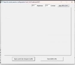
    Screenshot of panel and mode parameters configuration tool with an empty window. .
  • #24 21424430
    andreyatakum
    Level 14  
    salacpavel wrote:
    I was wondering if the "Sensible Code Configuration" is really the "Configuration.exe program" from rtd26660.rar, or should I download it elsewhere? If so, could you point me/us to the download location?
    .
    You can upload the file from the EPROM to correct it by the program "Panel and mode params...."-.
  • #25 21424537
    salacpavel
    Level 2  
    No worky worky. As said before, program launches and gives me File open dialog. Once I select .bin file I have downloaded from board flash memory (yup, 25xx40 is SPI Flash memory, not an EPROM), it just sits in tray for good 10 minutes only to spit out an empty canvas (picture above).
    Memory image from my board attached.
  • #26 21445076
    Marek Matysek
    Level 20  
    Hello to everyone watching this topic.

    Encouraged by the description, I purchased a PCB800099 V.9 and a cheap 1024x600 matrix. For some time I have been looking for a solution to replace the original display with some sort of LCD.
    I first tried the kit, connecting signals via AV and VGA. There is also HDMI but I am not interested in this type of transmission, I am most interested in the AV (CVBS) input as this is the signal my device gives. From the DVD player I checked the AV input and from the laptop the VGA.
    In both cases, the image quality is not shocking, although the internal software allows, with VGA, to work in several resolutions, as well as to adjust the position of the image and to switch in two sizes 4:3, 16:9. Brightness and Contrast do not work very well and this is mainly because the backlight brightness is fixed. A separate adjustment can of course be made, but for now this is not the most important thing.

    The AV input is poorer with position adjustment and picture size. Nothing can be done from the menu as this function is not available.

    However, I thought that since it was possible to 'poke around' in the software, it might work. After all, the panel will be permanently in the unit and will not be adjustable.

    And here is the whole point. The configuration program included in the zipped file does not work, as Pavel wrote above. The uploaded bin read from the ZB25VQ40 is minced for a few minutes or so to show an empty frame at the end, just like in some picture above. Files uploaded in Pretty codes the program opens after several seconds. The described windows are editable and seemingly everything is ok. Only that such a file uploaded to memory simply does not work. After switching on, the matrix flashes for a moment, then darkens and there is a raster, with no content on both inputs (AV and VGA), and that is all. Switching sources doesn't do anything either. The Menu does not appear.

    I decided to read up on the ZX-PK forum to find some guidance. Although it was hard to wade through the Russian technical dialect I read 31 pages, tested numerous batches with varying results. Some worked like Pretty codes, some caused the program to crash and didn't even respond to the keyboard

    I have no idea what I am doing wrong. I tried to register on ZX-PK, but the English-language platform is blocked, and no one is responding to registration on the Russian one.

    Have any colleagues grasped this topic yet?

    P.S..
    I read and write Flash on my old laptop via the LPT port with the proposed program in DOS, only that I found a newer version that already identifies the ZB25VQ40 memory. The recommended version does see the signature, but does not read the type and manufacturer because they are not in the library. But that doesn't change things.

    The only thing I can add to the article is that, when performing operations via the LPT port, a logic converter from 5V to 3.3V should be installed. The fact that you can manage without it, but there is a danger of flash damage, or at least various irregularities in communication. Anyway, on the ZX-PK forum this was also mentioned.
  • #27 21445196
    andreyatakum
    Level 14  
    Marek Matysek wrote:
    The only thing I can add from me to the article is that, carrying out operations via the LPT port, it would be necessary to install a logic converter from 5V to 3.3V. The fact, that it is possible to do without it, but there is a danger of flash damage, or at least various irregularities during communication. By the way, on the ZX-PK forum this was also mentioned.
    .

    Right, but I don't have an LTP port so I was reviving the arduino as a programmer. For many of the participants on the Russian language forums, this turned out to be the only solution to the problems of reading and uploading codes into the EPROM of this board.
    Marek Matysek wrote:
    I decided to read up on the ZX-PK forum to find some guidance. Although it was hard to wade through the Russian technical dialect I read 31 pages, tested numerous batches with varying results. Some worked like Pretty codes, some caused the program to crash and didn't even respond to the keyboard

    I have no idea what I am doing wrong. I tried to register on ZX-PK, but the English-language platform is blocked, and no one responds to registration on the Russian one.


    After reading about the problems here, I checked other forums. I think the most information can be found here: https://electronix.ru/forum/topic/178153-proshivka-kontrollera-displeya-na-baze-rtd2660/

    http://pccar.ru/showthread.php?t=27441
  • #28 21445433
    simw
    Level 27  
    LightOfWinter wrote:
    E.g. Samsung UE40D5500 and similar.
    .
    After all, this is a model that is probably already 15 years old.
  • #29 21445492
    Marek Matysek
    Level 20  
    Andrey, on those forums you gave links to, people are struggling with flash programming on the board, through various programmers including Arduino. I don't have these problems. I have kept an old laptop that has everything a self-respecting computer should have. From DOS or MS-DOS in Win98 I read and write without error. The same bin I read I upload again and everything works. I have no interference from the RTD side. I also uploaded the bin that Pavel posted and it also worked. Admittedly the image was inverted and mirrored, but this can all be set in the Menu accessible from the keyboard.

    I don't want to repeat what I mean, as I wrote about all this in my previous entry.

    An idea occurred to me. Do you have the same board? Did you edit your bin from that disc in Conftool? If so, can you post (upload to P.W.) it on the forum. I would like to see if it can be edited at my place and if it will work in my board. Maybe that way we can get to something.
  • #30 21445599
    andreyatakum
    Level 14  
    Marek Matysek wrote:
    An idea occurred to me. Do you have the same plate?
    .

    Unfortunately I damaged my disc not long before this article was published. But I have the file saved somewhere. If I can't find it I'll ask a friend.

Topic summary

The discussion revolves around the challenges of connecting retro computers to modern displays, particularly focusing on the use of laptop matrices and the RTD2660 module. Users express concerns about the compatibility of newer monitors with older graphics modes, particularly those operating at 15 kHz, which were common in retro computing. Some participants mention specific models of monitors and TVs that still support older connections like VGA, SCART, and RCA. There is also interest in building custom monitors using available components, but concerns about the practicality and cost-effectiveness of such projects are raised. Additionally, users share experiences with various adapters and configurations for retro computing setups.
Summary generated by the language model.
ADVERTISEMENT