logo elektroda
logo elektroda
X
logo elektroda

Flashing OpenBKN on ECGSOLAX 600W Micro Solar Inverter with BK7231N Chip

Zogdan 393 5
ADVERTISEMENT
  • Helpful post
    #1 21438650
    Zogdan
    Level 9  
    ECGSOLAX 600W Micro Solar Inverter With WiFI Grid Tie Pure Sine Wave Inverter MPPT Operating 20-50V Output 220V Micro Inverter

    This is an economic ( 70 eur ) solar inverter. Build quality is OK for its price. I will not say anything about the protections though.

    It runs on Tuya platform, and has a BK7231N chip, so definitely a nice candidate.

    Before flashing blindly OpenBKN, lets get some info first :

    Code: JSON
    Log in, to see the code


    IN API explorer : Query Things Data Model
    Code: JSON
    Log in, to see the code


    Code: JSON
    Log in, to see the code


    Table of Instructions

    DP Instruction -> Standard Instruction
    forward_energy_total -> forward_energy_total
    reverse_energy_total -> reverse_energy_total
    pv1_dc_data -
    phase_a -
    power_total power_total
    inverter_type -
    inverter_id -
    temp_current temp_current
    kg -
    glsz -

    GLSZ = set power 5 - 25 - 50 - 75 - 100 %
    kg = inverter switch

    Added after 1 [minutes]:

    >>21438650
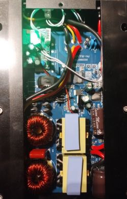
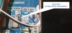
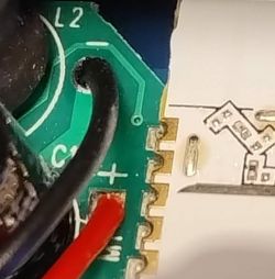
    Inside view of a solar micro inverter with electronic components.

    Close-up of a microinverter circuit board with obscured chip details.

    Black solar micro inverter ECGSOLAX GT-600 with several connectors, labeled 600W and 200V, and an EU logo at the top with delivery information.

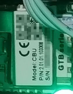
    Close-up of a microinverter chip with model CBU and GTB series markings.

    Added after 13 [minutes]:

    08 80 00 03 E8 00 27 10Now this is a kind of thing that I do not like that much:

    1. Phase A AC voltage, current, and power.
    2. Big-endian mode, HEX format, total of 8 bytes.
    3. Unit precision: Voltage (2 bytes, unit 0.1V), Current (3 bytes, unit 0.001A), Active power (3 bytes, unit 0.001kW).
    4. Example: 08 80 00 03 E8 00 27 10 represents Phase A voltage of 217.6V, current of 1.000A, power of
    10.000KW.
    5. Communication logic:
    A. When network configuration is successful, the MCU reports this data.
    B. The inverter reports this data periodically. Suggestion: Report every 1 minute in Wi-Fi mode and every 1 hour in NB mode.

    So this looks a bit like we would need to fiddle with tuyaMcu_defWiFiState
    Furthermore we would want smthing like this

    Code: C / C++
    Log in, to see the code
  • ADVERTISEMENT
  • ADVERTISEMENT
  • #3 21442791
    p.kaczmarek2
    Moderator Smart Home
    Very interesting device. I also noticed this fragment:
    Zogdan wrote:

    A. When network configuration is successful, the MCU reports this data.

    Maybe it relates to my recent finding about WiFi LED pin?
    https://www.elektroda.com/rtvforum/topic4089722.html

    So I see you basically need to have raw packet format added here?
    https://github.com/openshwprojects/OpenBK7231T_App/blob/main/src/driver/drv_tuyaMCU.c
    Search for DP_TYPE_RAW_TAC2121C_VCP in this file.
    We can add it for you easily and build binaries with online builds: https://www.elektroda.com/rtvforum/topic4033833.html
    You can also edit code yourself if you have Github account.


    Added after 59 [seconds]:

    Wait a second, doesn't your Voltage/Current/Power format already match DP_TYPE_RAW_TAC2121C_VCP ?
    Helpful post? Buy me a coffee.
  • ADVERTISEMENT
  • #4 21442794
    Zogdan
    Level 9  
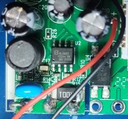
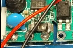
    The power measurement breakout board uses a BL0937 so I'll try that one first.

    Close-up of a circuit board with BL0937 integrated circuit and attached wires.

    Added after 2 [minutes]:

    tuyaMcu_defWiFiState 4 halts the BK and led starts flashing rapidly. Will try other wifi states.

    Added after 10 [minutes]:

    >>21442794 Actually I bought this as a "starter kit" for using openbkn on a similar inverter that has a 433mhz receiver piggybacked to the CBU, paired to a 433 power meter to throttle the feed in of the inverter so there is a zero net injection. This inverter supports throttling, but playing with that ( "5", "25", "50", "75", "100") is at least weird since what % are we talking about? Rated power? When changing this param I did not see any noticeable change in PV power or output.

    Added after 8 [minutes]:

    >>21442794 >>21442791 Thanks, I'll trace back the black/red line, seems like it's just power, and the board only connects the .001 shunt for measurement, so I'm puzzled how this output power % is even working. Could be it is defined in tuya but not implemented in hardware? Or that they just use a generic tuya template without actually working? Wouldn't be the first time that we see a mismatch.
  • ADVERTISEMENT
  • Helpful post
    #5 21444287
    Zogdan
    Level 9  
    After startdriver TuyaMCU we see some activity, but then no further activity is seen and the CBU stops.

    Reported : id 101 (switch), id 102 ( power %), 15 (device model), 16 (device id)

    Displaying TuyaMCU messages in text format

    Info:CMD:[WebApp Cmd 'startdriver TuyaMCU' Result] OK

    Info:TuyaMCU:Consumed 51 unwanted non-header byte in Tuya MCU buffer
    Info:TuyaMCU:Skipped data (part) 00 00 00 00 00 00 00 00 00 00 00 00 00 00 00 00 00 00 00 00 00 00 00 00 00 00 00 00 00 00 00 00 00 00 00 00 00 00 00 00 00 00 00 00 00 00 00 00 00 00 E0

    Info:TuyaMCU:Received: 55 AA 03 01 00 2A 7B 22 50 22 3A 22 63 7A 75 37 79 6E 6F 73 72 6B 78 67 62 6E 73 62 22 2C 22 76 22 3A 22 31 2E 30 2E 30 22 2C 22 6D 22 3A 30 7D 82

    Info:TuyaMCU:ProcessIncoming[v=3]: cmd 1 (QueryProductInformation) len 49
    Info:TuyaMCU:ParseQueryProductInformation: received {"P":"czu7ynosrkxgbnsb","v":"1.0.0","m":0}

    Info:TuyaMCU:Received: 55 AA 03 02 00 00 04
    Info:TuyaMCU:ProcessIncoming[v=3]: cmd 2 (MCUconf) len 7
    Info:TuyaMCU:ProcessIncoming: TUYA_CMD_MCU_CONF, TODO!

    Info:TuyaMCU:Received: 55 AA 03 07 00 05 65 01 00 01 00 75
    Info:TuyaMCU:ProcessIncoming[v=3]: cmd 7 (State) len 12
    Info:TuyaMCU:ParseState: id 101 type 1-bool len 1
    Info:TuyaMCU:ParseState: byte 0
    Info:TuyaMCU:Received: 55 AA 03 07 00 05 66 04 00 01 00 79
    Info:TuyaMCU:ProcessIncoming[v=3]: cmd 7 (State) len 12
    Info:TuyaMCU:ParseState: id 102 type 4-enum len 1
    Info:TuyaMCU:ParseState: byte 0
    Info:TuyaMCU:Received: 55 AA 03 07 00 0E 0F 03 00 0A 47 54 42 20 73 65 72 69 65 73 BB
    Info:TuyaMCU:ProcessIncoming[v=3]: cmd 7 (State) len 21
    Info:TuyaMCU:ParseState: id 15 type 3-str len 10
    Info:TuyaMCU:Received: 55 AA 03 07 00 0A 10 03 00 06 31 30 31 35 35 35 5D
    Info:TuyaMCU:ProcessIncoming[v=3]: cmd 7 (State) len 17
    Info:TuyaMCU:ParseState: id 16 type 3-str len 6
    Info:TuyaMCU:Received: 55 AA 03 34 00 01 04 3B
    Info:TuyaMCU:ProcessIncoming[v=3]: cmd 52 (TUYA_CMD_REPORT_STATUS_RECORD_TYPE) len 8
    Info:TuyaMCU:0x34 command 4
    Info:TuyaMCU:Received: 55 AA 03 00 00 01 01 04
    Info:TuyaMCU:ProcessIncoming[v=3]: cmd 0 (Hearbeat) len 8
    Info:TuyaMCU:Received: 55 AA 03 03 00 00 05
    Info:TuyaMCU:ProcessIncoming[v=3]: cmd 3 (WiFiState) len 7

    Info:MQTT:mqtt_host empty, not starting mqtt

    Info:TuyaMCU:Received: 55 AA 03 00 00 01 01 04
    Info:TuyaMCU:ProcessIncoming[v=3]: cmd 0 (Hearbeat) len 8

    Added after 40 [minutes]:

    Ok lets find out what this presumed power cable is doing.


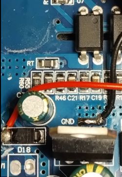
    Close-up of a circuit board with connected cables.

    this seems to deliver power to the powermeasurment/CBU module, but guess what : 0 volt while running.

    This is the corresponding connection to the main board :


    Close-up of a circuit board with electronic components and wiring

    That looks as a power supply line to me, but with 0v ?

    This thing is no fun to dissassemble so probable the module might have its own power supply since it is soldered only to L-N-N, having 220v between L-N and N-N is the shunt.


    Close-up of a circuit board featuring a BL0937 chip and soldered wires.


    The 5V-GND is 0v as well.

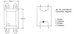
    The use of the optocoupler ORPC-817SC-TP-F is not clear

    Internal connection diagram of an optocoupler

    Loading BL0937 driver does not crash the CBU, but nothing is shown either.

    I am seriously puzzled how the main board CPU even communicates with the BL/CBU board.

    Added after 24 [minutes]:

    Ok one step further :

    It seems that i need to issue
    backlog startdriver TuyaMCU; tuyaMcu_defWiFiState 4;
    so that the time between starting the driver and settting the WiFistate should be short?

    1 ,Total forward active energy
    2 ,Total reverse active energy
    3 ,Input
    7 ,Output
    10, Total power
    15,Inverter type
    16, Inverter ID
    18, Inverter temperature
    101,inverter switch
    102,Output power setting

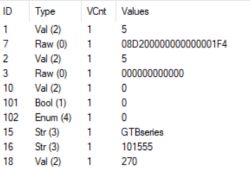
    We get all back except for temperature :


    TuyaMCU controller data table showing various IDs and values.

    Lets check tuya data for id 7

    Quote:
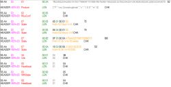
    55 AA 03 07 00 0E 07 00 00 0A 08D200000000000001F4 F7
    HEADER VER=03 State LEN fnId=7 Raw V=08 D2 00 00 00 00 00 00 01 F4 CHK


    So following the "instructions" for ID 7 at the beginning of this post let’s decode the provided HEX data:

    HEX Input:
    08 D2 00 00 00 00 00 00 01 F4

    Voltage: 2 bytes (unit: 0.1 V)
    Current: 3 bytes (unit: 0.001 A)
    Power: 3 bytes (unit: 0.001 kW)

    Let’s assume the relevant portion is the first 8 bytes and the rest is some checksum

    First 8 Bytes: 08 D2 00 00 00 00 00 00
    Voltage (2 bytes) = 0x08D2 = 2258 * 0.1V = 225.8V
    Current (3 bytes) 0x000000 = 0 * 0.001A = 0.000A
    Power (3 bytes) 0x000000 = 0 * 0.001KW = 0.000 kW

    That makes sense :)

    So now ill hook it up to a power supply to get fresh tuya data. 
  • #6 21447064
    Zogdan
    Level 9  
    Just thinking loud, a generic command like
    splitanddecodehex( hexvalue, startbyte, length, format )
    would make sense to have

    eg
    $voltage = splitanddecodehex $CH7 3 2 INT

    I will try
    linkTuyaMCUOutputToChannel 6 RAW_TAC2121C_VCP
    first
ADVERTISEMENT