logo elektroda
logo elektroda
X
logo elektroda

Wireless doorbell - can it work without batteries? Battery-free transmitter

p.kaczmarek2 2685 18
ADVERTISEMENT
Treść została przetłumaczona polish » english Zobacz oryginalną wersję tematu
  • Aigostar wireless doorbell on a table with instructions in the background .
    Wireless solutions are often considered more convenient and handy than wired ones. Installation is easier, there is no need to pull cables, drill, hide them under angles and combine how to do it aesthetically. There is, however, an inconvenience - the need to regularly replace the battery, which usually dies at the least convenient moment. But are we sure? Perhaps we could do things differently? Let's find out!

    Today, a product bought in our country for all of PLN 45 comes to the table. Here we have a wireless and battery-free wicket doorbell with IP44 rating, i.e. resistant to small particles and water splashes. The product model is U6A-N6A , and the product itself offers:
    - battery-free transmitter
    - receiver powered from the mains
    - 36 melodies to choose from
    - range up to 150 m under ideal conditions
    - a volume level of up to 100dB
    We did a bit of digging around when buying this product, as you can find all sorts of nonsense in the offers, including silence about batteries in the case of the battery-operated transmitter, as well as talk of batteries in the case of the transmitter.... battery-free:
    Advertisement graphic for a wireless doorbell with a plug-in receiver. .
    Well, but that's probably the result of copying without checking the bid description. In any case, it's time to look at what we received in practice:
    Packaging of Aigostar self-powered wireless doorbell .
    Wireless and battery-free doorbell Aigostar in packaging. .
    English-language name: "self-powered AC wireless doorbell".
    The contents of the kit itself are nothing to discuss, as the bare minimum is here - and we don't need more:
    Aigostar wireless doorbell with instructions and packaging. .
    Instructions in Polish and English (clear pictures):
    User manual for a self-powered wireless doorbell. .
    Instruction manual for a wireless doorbell. .
    The workmanship plastic is quite solid, it is not the cheapest plastic of which torches from China, for example, are made.

    The whole thing works without pairing:


    .
    There are two buttons on the receiver housing - melody selection and voice level:
    Close-up of buttons on wireless doorbell receiver housing .


    .
    We are most interested in the transmitter, so we will start with the receiver.
    Receiver of a wireless, battery-free doorbell with speaker grill and inspection stickers. .
    Close-up of a label with CE and RoHS certifications and a barcode. .
    The board is single sided, mixing through-hole and surface mount.
    Interior of a wireless doorbell receiver showing the circuit board. .
    Close-up of the interior of a wireless doorbell receiver. .
    Receiver PCB of wireless doorbell .
    Close-up of electronic internal components. .
    Close-up of electronic components on a PCB. .
    Close-up of an electronic enclosure interior showing wires and components. .
    There is no step-down converter for mains power, the power supply is realised by a transformerless power supply on a capacitor. The input is also protected by a fuse. A little further on you can see the MB10E rectifier bridge. From its 'plus leg' there is a connection to a 1000uF electrolytic capacitor and a Zener diode, presumably this is the power supply stabilisation and filtering circuit.
    Further down the line things get a bit more complicated:
    Close-up of a printed circuit board with integrated circuits. .
    Close-up of a PCB with electronic components. .
    Close-up of a printed circuit board with visible electronic components .
    The CMT2210LB is an RF receiver, you know. He also has a 27MHz quartz resonator in his circuit.
    Technical specifications for the Hoperf CMT2210/17LB RF receiver. .
    CMT2210/17LB typical application schematic .
    That leaves two chips. SXD089A - I couldn't find any information about it online, but it seems to be connected to the speaker via the S+ and S- pads, so maybe it's an amplifier?
    The other is an FMD 82RQRKE or similar. The output of the RF receiver is connected to it:
    Close-up of a printed circuit board with two integrated circuits. .
    So it's probably the MCU. The buttons are probably operated by him too. He's probably the one playing the melody, which is then amplified.
    Inside of a wireless doorbell receiver. .

    Now for the most interesting part, which is the transmitter:
    Aigostar wireless doorbell receiver on a wooden table with instructions in the background. .
    A wireless and battery-free doorbell lying on the table. .
    The first thing that catches the eye is the antenna:
    Disassembled wireless doorbell transmitter with visible circuit board inside. .
    Here we also have an RF transmitter along with a resonator and a circuit that looks like an inverter. The power, however, actually comes from a generator that converts the force of pressing the button into current:
    Close-up of the interior of a wireless battery-free doorbell transmitter. .
    You can even see the coil from this generator, while I did not dismantle it more, I did not want to damage the product.
    Circuit board of a battery-free doorbell transmitter. .
    Indeed, it takes a bit of force to push it in, this is no ordinary microswitch:


    .
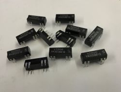
    It remains to specify the name of the RF transmitter chip - CMT2150L.
    CMOSTEK CMT2150/57L chip specification. .
    It is interesting that this chip supports up to 6 buttons, but only one is used here:
    Typical application schematic diagram for CMT2150/57L .

    The question of mounting remains - I didn't take a picture, but the instructions show that the transmitter has a separate frame which can be fixed with double-sided tape or screws. I refer you to the instructions for details.

    In summary , the transmitter does indeed work battery-free and the whole thing performs well for a £45 purchase with same day shipping. From China it might even have been cheaper. The choice of tunes is wide and the voice level control is also useful. By the way, I also tried to play around with the range, but within my small flat I didn't manage to 'lose' it even though there were two rooms between the transmitter and receiver.
    One might even say that I'm a little surprised that there are so many solutions available similar to this one, but battery-powered, when battery-free can do the job too....
    And what is your opinion - have you used this type of battery-free mechanism, and if so, where?

    Cool? Ranking DIY
    Helpful post? Buy me a coffee.
    About Author
    p.kaczmarek2
    Moderator Smart Home
    Offline 
    p.kaczmarek2 wrote 11906 posts with rating 9976, helped 571 times. Been with us since 2014 year.
  • ADVERTISEMENT
  • #2 21461286
    krzbor
    Level 27  
    It's a pity you didn't describe exactly the most interesting thing - i.e. how this current is generated. A bit of current is needed, however - apart from the transmitter itself, there is also the LED.
  • ADVERTISEMENT
  • #3 21461301
    vodiczka
    Level 43  
    krzbor wrote:
    It's a shame you didn't describe exactly the most interesting thing - i.e. how this current is generated.
    Probably described, just a bit mysteriously
    p.kaczmarek2 wrote:
    Realistically, it takes a bit of effort to push it, it's no ordinary microswitch:
    .
    I'm betting on a microswitch but it could also work with a piezo effect.
  • #4 21461324
    nukedclxx
    Level 6  
    https://electgo.com/product/se-zbrt2, at work we have a machine remote control based on something like this. It works, but sometimes you have to push it a few times to get it to work. I would gladly replace it with a battery operated one.
  • #5 21461363
    acctr
    Level 38  
    krzbor wrote:
    It's a pity you didn't describe exactly the most interesting thing - i.e. how this current is generated. A bit of current is needed though - apart from the transmitter itself there is also the LED.

    vodiczka wrote:
    I'm betting on a microdynamo but it could also work based on a piezo effect.
    .

    After all he has shown, you can see the coil. Energy requirement to send a "ringing" packet less than when lighting a cigarette lighter.
    Helpful post? Buy me a coffee.
  • ADVERTISEMENT
  • #6 21461581
    Borygo123
    Level 28  
    Similar bells are made by Zamel, for example. I have had it for several years and it works great. And most importantly, I don't have to worry about the battery in the transmitter at the gate.
  • #7 21461611
    krzbor
    Level 27  
    acctr wrote:
    It showed, you can see the coil.
    .
    I have yet to see a coil generate a current by itself. For that you need an alternating magnetic field. I was just wondering how this is done. It's more likely that putting the magnet in and out of the coil isn't enough (although I may be wrong). Maybe there's a mechanism to put the magnet in a spinning motion - that would certainly extend the pulse.
    Maybe a piezo as described here: Link .
  • #9 21461728
    acctr
    Level 38  
    krzbor wrote:
    I have yet to see a coil generate a current by itself. For that you need an alternating magnetic field.
    .
    All the more so if you can see the coil the rest you can add/draw for yourself, as befits homo sapiens.
    Helpful post? Buy me a coffee.
  • #10 21461947
    operator5wp
    Level 16  
    I have this type of bell, maybe a different model and company but I wouldn't want any other for a long time and I can safely recommend this type of bell. Previously I had various battery-powered bells and there were problems with the range, especially as I have a metal fence with thick profiles so sometimes I had problems with signal reception that the range dropped to 5-7m. In winter there were also problems with the battery-powered one, when it was freezing cold the battery would die and no one in the house would know about it. Now that I have the battery-less unit, there are no problems, even thick walls or metal fences do not interfere with the signal. Maybe there is one disadvantage, that you have to press the button on the transmitter well, or sometimes twice, then the right voltage is charged, but this is a minor problem. In my version there is no memorisation of previous settings in the receiver, which restores the default bell and volume settings after a power failure. Do you also have a lack of memorisation of settings after a mains power failure?
  • #11 21462134
    Borygo123
    Level 28  
    Mine remembers the settings.
  • ADVERTISEMENT
  • #12 21462151
    Krzysztof Kamienski
    Level 43  
    That is, a return to the Soviet dynamo torch as the ,,clou of the programme". The rest is a cliché, but fact, not a stupid device.

    Black Soviet dynamo flashlight with a metal crank. .
  • #13 21462242
    acctr
    Level 38  
    operator5wp wrote:
    I had various battery operated ones before and there was a problem with range, especially as I have a metal fence with thick profiles so sometimes I had problems with signal reception that the range dropped to 5-7m. In winter there were also problems with the battery-powered one, when it was freezing cold the battery would die and no one at home would know about it. Now that I have the batteryless there is no problem, even thick walls or metal fences do not interfere with the signal.
    .
    Interesting point, perhaps this type of bell has a more advanced protocol optimised for energy, i.e. it sends short but strong signals with equalization and checksum.
    Helpful post? Buy me a coffee.
  • #14 21463804
    klamocik
    Level 36  
    I watched a video on You, the guy connected the LED to a ceramic plate and by tapping it with his finger it lit up quite beautifully.
  • #15 21463857
    acctr
    Level 38  
    klamocik wrote:
    I watched a video on You, a guy connected a diode to a ceramic plate and by tapping it with his finger it lit up quite beautifully.
    .
    Piezo effect.
    Helpful post? Buy me a coffee.
  • #16 21464634
    krzbor
    Level 27  
    acctr wrote:
    krzbor wrote:
    I have yet to see a coil generate a current by itself. For that you need an alternating magnetic field.
    .
    All the more so if you see a coil the rest you can add/draw for yourself, as befits homo sapiens.

    Man of reason - draw the rest :) .
  • #17 21464944
    Krzysztof Kamienski
    Level 43  
    @krzbor Too smart I'm not, but I digress - the worm when pressed turns the rotor of the alternator, like in communist children's farts.

    Colorful Peg Top toy in packaging and spinning with lights.
  • #18 21465076
    krzbor
    Level 27  
    Krzysztof Kamienski wrote:
    I'm not very smart but I get it - the worm turns the rotor of the alternator when pressed, like in communist children's farts.
    .
    Or perhaps when pressing, a spring is tightened, which at some point is released and an oscillating movement of the magnet in the coil is created?
    Or perhaps even more simply as EnOcean does:
    Copper coil mounted in a black plastic holder. .
    From 7:34


    I know that you enjoyed the blurb. However, I am interested in the actual solutions.
  • #19 21465084
    acctr
    Level 38  
    The pictures show the coil and the PCB shows the two legs from it, connected to the rectifier bridge:

    The image shows a coil and two leads on a PCB connected to a rectifier bridge. .

    Close-up of PCB with marked coils and rectifier bridge.

    This indicates that the energy is provided by a coil and, assuming this equipment obeys the known laws of physics, there should be some sort of core underneath the PCB, housed inside the black casing.
    Simply moving the button is a linear movement and such a changing magnetic field is unlikely to induce a large enough current.
    The key issue, then, is how to transmit the movement of the button to the core. In one of the videos you can hear how the button works - there is a clearly audible 'click' which means that at some point something jumps.
    Presumably the movement of the lever is transmitted to the spring, which at some point causes the core to change position quickly, similar to what happens, for example, in microswitches used in computer mice


    .

    The core has two stable states corresponding to its position relative to the coil and the transition between them is a correspondingly large dΦ/dt.


    PCB with electronic components, including a coil and a bridge rectifier. .
    Helpful post? Buy me a coffee.

Topic summary

The discussion revolves around a wireless, battery-free doorbell model U6A-N6A, which operates using a mains-powered receiver and a transmitter that generates current through mechanical action, possibly utilizing a microswitch or piezoelectric effect. Users express curiosity about the current generation mechanism, with suggestions including the use of coils and magnets. Several participants share their experiences with similar devices, highlighting advantages such as eliminating battery replacement issues and improved signal range, especially in challenging environments like metal fences. Some users note minor operational quirks, such as the need for a firm press on the transmitter button to ensure proper function.
Summary generated by the language model.
ADVERTISEMENT