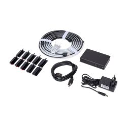
The Smart HDMI Sync Box by Eurodomest was offered cheaply at Action in November 2024 and normally used with the LSC Smart Connect app.

Principle of operation
The incoming video signal is duplicated with an HDMI splitter GSV2002 (18 Gbit/s, HDMI 2.0, HDCP 2.2) by GSCoolink, whereby one is forwarded directly to the screen and the other is first scaled (1080p?). An HDMI-to-VGA converter CS5210 by ASL (6204000100) or MX9291 by ? (6204000102) then breaks down the image signal into its RGB components for evaluation on the central microcontroller ESP32-D0WD-V3 by Espressif. The connection to the Tuya cloud and control of the LED strip is carried out using the CBU radio-frequency module by Tuya, which has a BK7231N microcontroller by Beken. The RGBIC LED strip is designed for screens with a diagonal of 55 to 65 inches (3-sided, 2.6 m) and has a total of 84 LEDs with 28 addressable sections.
HDCP copy protection is applied correctly, ensuring a successful handshake between the player and the screen. An unencrypted signal for extracting the colors of the outer image area is only available within the device. Accordingly, the bias lighting also works with protected content such as streaming services (Netflix etc.) or Blu-ray discs.
Research
A CloudCutter profile is already available for installing OpenBeken. However, the pin assignment could not be read out with the firmware dump and UART output, so it was determined by tracing the tracks. The ESP32-D0WD-V3 (master) and BK7231N (slave) microcontrollers communicate via SPI. Pin P0 and P8 of BK7231N control the LED strip, whereby they represent the inputs of a NOR gate and its output corresponds to the data line.

The initial communication of the device in EZ mode recorded with a logic analyzer can be decoded using Logic 2 by Saleae as WS2812B protocol. P8 is actually permanently low and turns on the LED strip by high at the beginning. P0 corresponds to the inverted signal, which can be decoded.

A driver is now required which corresponds to the inverted actual signal for WS2812B. In addition, contrary to the existing SM16703P driver for P16 (MOSI), this is required on P8 without SPI. The transmission of the image information from the ESP32-D0WD-V3 to the BK7231N with SPI must then be examined in order to ensure that the LED strip is controlled in accordance with the image content.

| Brand name | Eurodomest | Eurodomest | Eurodomest | Eurodomest | Product name | Smart HDMI Sync Box | Smart HDMI Sync Box | Smart HDMI Sync Box | Smart HDMI Sync Box | Product number | 6204000100 | 6204000102 | 6204000150 | ? | GTIN-13 (EAN-13) | 8712879162834 | 8712879162834 | ? | 8712879162889 | Article number | 3207950 | 3207950.1 | ? | 3017060 |
Principle of operation
The incoming video signal is duplicated with an HDMI splitter GSV2002 (18 Gbit/s, HDMI 2.0, HDCP 2.2) by GSCoolink, whereby one is forwarded directly to the screen and the other is first scaled (1080p?). An HDMI-to-VGA converter CS5210 by ASL (6204000100) or MX9291 by ? (6204000102) then breaks down the image signal into its RGB components for evaluation on the central microcontroller ESP32-D0WD-V3 by Espressif. The connection to the Tuya cloud and control of the LED strip is carried out using the CBU radio-frequency module by Tuya, which has a BK7231N microcontroller by Beken. The RGBIC LED strip is designed for screens with a diagonal of 55 to 65 inches (3-sided, 2.6 m) and has a total of 84 LEDs with 28 addressable sections.
HDCP copy protection is applied correctly, ensuring a successful handshake between the player and the screen. An unencrypted signal for extracting the colors of the outer image area is only available within the device. Accordingly, the bias lighting also works with protected content such as streaming services (Netflix etc.) or Blu-ray discs.
Research
A CloudCutter profile is already available for installing OpenBeken. However, the pin assignment could not be read out with the firmware dump and UART output, so it was determined by tracing the tracks. The ESP32-D0WD-V3 (master) and BK7231N (slave) microcontrollers communicate via SPI. Pin P0 and P8 of BK7231N control the LED strip, whereby they represent the inputs of a NOR gate and its output corresponds to the data line.

The initial communication of the device in EZ mode recorded with a logic analyzer can be decoded using Logic 2 by Saleae as WS2812B protocol. P8 is actually permanently low and turns on the LED strip by high at the beginning. P0 corresponds to the inverted signal, which can be decoded.
A driver is now required which corresponds to the inverted actual signal for WS2812B. In addition, contrary to the existing SM16703P driver for P16 (MOSI), this is required on P8 without SPI. The transmission of the image information from the ESP32-D0WD-V3 to the BK7231N with SPI must then be examined in order to ensure that the LED strip is controlled in accordance with the image content.


