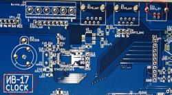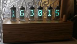
Description and presentation below , designed and made by me, clock based on VFD IV-17 tubes .
The impulse to make the clock is largely inspired by the video presentation of the Wiktor clock in action:
https://www.elektroda.pl/rtvforum/topic3196412.html
The design uses the application notes of the VFD lamp
http://www.spark-tube.com/wp-content/uploads/2018/08/iv-17-datasheet.jpg
https://www.eevblog.com/forum/projects/driver-for-iv-4-iv-17-18-segment-vfd-tube/
Having previously made a clock on the IV18 lamp (and gained some experience), I decided that it was time to start with a much more complicated - much more representative 18-segment IV17 lamp.
Note here: IV4 (IV-4, ИВ-4) and IV17 (IV-17, ИВ-17) tubes are replacements, and sometimes the designation IV4 may appear in this description.
The main assumptions for the design of the IV17 clock
- clock on 6 IV17 tubes;
- use of the HV integrated circuit to control the segments (in the IV18 clock I used NPN keys to control the segments, it's possible, but a lot of extra work);
- the control element will be STM32F103.
Scheme of the clock IV17
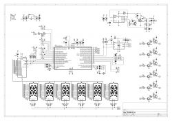
Overview of the essential circuits:
The construction of the clock boils down to the proper power supply and logic operation of 6 VFD IV17 tubes. By assumption, for the 18-segment VFD, the mode of operation with multiplexed display was selected.
POWER
High voltage DC power supply based on the standard MC34063, with an interesting option to improve the MOSFET control, borrowed from the link:
http://mirley.net/boost_converter_for_lamp_nixie.html
A 120µH inductor (Imax > 1 A) was used, a MOSFET transistor IRL540 with reduced turn-on voltage U GS(th) . The output voltage of this DC-DC converter is 45 V. This voltage value was selected in order to extend the life of the VFD lamps (for multiplexed operation, the note suggests 50-70 Vdc, for static operation 25-30 Vdc) while maintaining sufficient brightness.
The power supply of the lamp filaments with 1R resistors included in the circuits was selected so as to ensure the catalog operating conditions U fill ~2.4 V. The polarity of the glow potential was changed - the integrated circuit of the L9110 bridge was used.
CONTROL
According to the assumptions, the SMT32F103C8T6 microcontroller was used (used e.g. in BluePill modules). The main control of the 18 segments is carried out by means of the HV5812 integrated high-voltage demultiplexer (a simple serial protocol with timing), while the 45 Vdc switching for the grids of 6 IV17 lamps was performed on the NPN (BC847)-PNP (BC856) keys. For the sake of clarity, the 18 220k resistors accelerating the discharge of the switched anode voltages are not shown.
The system has an active battery backup circuit (CR1220), the time source is an internal RTC with an external 32768 Hz quartz connected. Correction of RTC clock accuracy is possible in two stages (correction_1 of 24h time and correction_2 of 14 days) by entering deviations in settings menu .
There are 5 levels of display brightness adjustment - this is done by changing the duty factor (Ugrid activity) for a given time slot of a specific VFD lamp. max. lighting level of VFD lamps selected in settings menu.
U neigh polarity change timing fill through outputs (PWM 50%) complementary Timer1 - with a frequency of approx. 102 Hz.
The clock is prepared to work with data from the weather station, which it receives via USART3_9600 (Z2 connector) as a frame with 28B (temperature, pressure, humidity, ubatt, lux, - description of the frame in the attachment *txt). Work without the above data from the weather station is possible, only the VFD lighting level - then it is not automatically set to the current value of natural lighting [lux] received from the weather station.
Settings menu available via classic encoder: up/down/enter. In the settings you can select: display mode (only_time/time+date/time+weather_data), max. VFD lighting level, enter: 2 degrees of clock accuracy corrections.
Due to the large number of available digital interfaces in the STM32F1, an interface for possible communication with Raspberry I/O, other devices via SPI or I2C has been added to the diagram.
HOUSING, PCB - execution
The actual execution of the clock is based on 3 PCBs:
– main board includes: µC, all power supply circuits, HV5812 segment driver, USART, SPI, I2C interfaces;
– Display intermediate board includes: NPN (BC847)-PNP(BC856) keys to control 6 grids of VFD tubes, 2xIDC12 connectors for each IV17 tube;
– VFD IV17 tube board includes: 2xIDC12 connectors, 1 IV17 tube.
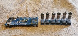
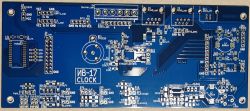

Such a division of the pcb gives a certain versatility to build a clock/device based on other VFD tubes (for example IV11 for me). Then only dedicated boards for the VFD lamp and redesign of a simple intermediate display board are needed. The motherboard with µC remains unchanged.
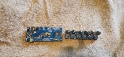
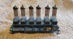
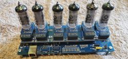
Wooden casing made of ordered cut 3 oak planks 17 mm glued together, forming the proper shape. Then, the place for the PCBs was carefully drilled and 20 mm holes were drilled for the VFD lamps, 6 mm holes for the encoder and a hole for the USB_print power connector. The lower part of the housing is covered with a cut 3 mm fibreboard. All painted with shellac.
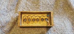

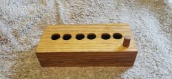
The startup itself went smoothly, the power supply on the MC34063 generates 45 V, the voltage practically does not drop when the display is loaded. The clock supply current of about 400 mA is mainly the current of the lamp heating circuits (I fill approx. 300mA).
A separate matter is the µC software, defining your own characters for the 18-segment display and developing ways to correct the inaccuracy of the 32768 Hz quartz resonator ... it took some time.
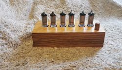
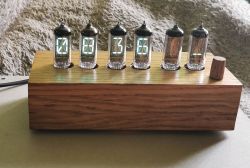
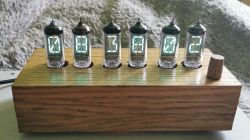
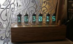
In addition to photos of the clock's elements, I am posting a short video of the clock's operation (the option to display time + weather data is visible). Unfortunately, the photos and the video do not fully reflect the color and smoothness of the animation (no flickering is visible in real life) :(
Additionally, in the attachment *.bin batch for STM32F103C8T6.
Summary
The basic cost is the lamps, approx. PLN 100, the cost of making the plates PLN 100, the rest of the elements max. PLN 100. Total PLN 300, but of course another clock like this would cost PLN 150. The only thing that would still be equally difficult would be the work/adaptation of the wooden housing to the electronics.
The optical impressions of the working clock on 6 IV17 lamps, as for me, visually pierce the IV18 lamp. Larger numbers, more complex shapes, the possibility of mini-animation. Of course, the hypnotic/calm turquoise VFD color is unchanged :)
Designing and building the clock took me several months in 2022, and this post is the end of my VFD adventures started by the clock on IV18 in 2020.
Cool? Ranking DIY


