Elektroda.com
Elektroda.com
X

Clock with VFD display IVL1-7/5 based on KR145IK1911 and DS32kHz

mkpoz 7086 44
This content has been translated flag-pl » flag-en View the original version here.
  • The growing popularity of VFD displays, their relatively low price and interesting appearance prompted me to build a clock based on such a display.

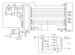
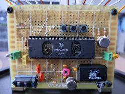
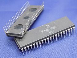
    The heart of the clock is one of the oldest specialized Soviet microcircuits for electronic clocks made in the p-MOS technology КР145ИК1911 (KR145IK1911) in a 40-DIP housing. The system has the ability to control external devices or simply can be used as an alarm clock and timer. In my solution, I did not use these functions. The whole was assembled on a universal printed circuit board.

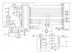
    The power section remained on the original board from the damaged clock. The КР145ИК1911 microcircuit requires a DC power supply of -27V, it comes from a stabilizer based on a rectifier bridge, zener diodes and a transistor. A low-power transformer with two secondary windings is used, one to obtain a voltage of -27V, and the other to obtain an alternating filament voltage of 5V. Since the heating circuit of the display is also the cathode, the transformer has a tap in the middle of the winding. In order to extend the life of the display, the filament voltage is reduced to about 4.8V. The clock is also equipped with a main oscillator backup system based on two A23 batteries connected in series.

    At the outputs of the microcircuit 12-18, a seven-segment digital code is generated. To indicate the numbers, the VFD display ИВЛ1-7/5 (IVL1-7/5) with multiplex control is used. The signals from the КР145ИК1911 system control the potential of the anodes of individual digits and service marks, ensuring their alternate activation. Only one digit is displayed at a time, but the transition from one digit to another occurs at a frequency of 500Hz, which makes the digits on the display appear to be continuous to our eye. The flashing of the service marks (dots) of the display is done by giving a 1 Hz signal from the output 22. The clock also has the function of blanking the insignificant zero when displaying one-digit hours, based on a transistor and two resistors.

    The main oscillator is inside the chip connected to a standard 32.768kHz watch quartz oscillator. The oscillator was initially connected to a resonator system and two 20pF capacitors. However, its accuracy was not satisfactory, which I wrote about here: https://www.elektroda.pl/rtvforum/topic3852502.html.
    So I decided to add additional capacitance to the system in the form of a 4.2-20pF trimmer capacitor. Despite numerous attempts to adjust the frequency and replacing the capacitors with a slightly larger capacity (22pF), I decided to look for another solution.

    The original version of the clock:
    Clock with VFD display IVL1-7/5 based on KR145IK1911 and DS32kHz

    Finally, as an oscillator I used a specialized DS32kHz system from Dallas, which is a temperature-compensated quartz oscillator (TCXO) with an output frequency of 32.768kHz. It is powered by the 78L03 stabilizer with 3V. It also has a power backup, which is based on the backup power supply of the main oscillator of the КР145ИК1911 chip. The used DS32kHz system, according to the manufacturer, has a deviation of ±2ppm, which gives ±1 minute / year (0.17 seconds / day). The system works perfectly, the movement of the clock is very accurate. Now, after three months of uninterrupted operation of the clock, the deviation from real time was about +0.03 seconds / day (+0.9 seconds / month), which gives an accuracy of ±0.3 ppm!
    According to the manufacturer's data sheet, it is worth supplying the DS32kHz system with a voltage close to 3V to achieve greater stability, as you can see it gives very good results.

    Final connection diagram:
    Clock with VFD display IVL1-7/5 based on KR145IK1911 and DS32kHz

    Plate:
    Clock with VFD display IVL1-7/5 based on KR145IK1911 and DS32kHz

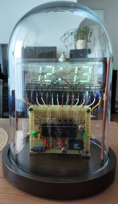
    Clock appearance:
    Clock with VFD display IVL1-7/5 based on KR145IK1911 and DS32kHz Clock with VFD display IVL1-7/5 based on KR145IK1911 and DS32kHz Clock with VFD display IVL1-7/5 based on KR145IK1911 and DS32kHz

    Cool? Ranking DIY
    About Author
    mkpoz
    Level 10  
    Offline 
    mkpoz wrote 54 posts with rating 58. Live in city Poznań. Been with us since 2008 year.
  • #2
    gulson
    System Administrator
    Revelation. I associate VFD displays with a Russian watch and video recorder. In my life, I would not have thought that the fashion for these rather cold displays would come back ;)
    A great idea for the housing, it was certainly not easy to put it together so that it would make an impression in a transparent housing, where you can really see every solder.
    Write to me with a parcel locker and I will send a gift for DIY presentations :)
  • #3
    robig
    Level 21  
    Great idea for the housing and execution under it.
    I have seen and still have a lot of Russian systems, and this one is interesting because of these two windows. Are they for something or something?
  • #4
    mkpoz
    Level 10  
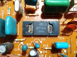
    Good question, what are these "windows" in KR145IK1911 for. It is interesting because this microcircuit was produced in a version without and with "windows" (I have both types).
    Looking at the production date, I came to the conclusion that the later ones have such a strange casing (I am not sure about that). But what these holes mean, I have no idea.
    From my point of view, this layout with "windows" looks much more attractive, which is why I used it.
  • #5
    tomekptk
    Level 17  
    mkpoz wrote:
    Good question, what are these "windows" in KR145IK1911 for. It is interesting that this microcircuit was produced in a version without and with "windows" (I have both types)

    Those who remember this "system" know that there was simply no (after all, everything was still missing at that time) proper housings, so they were loaded with windows that were supposed to be, for example, for EPROM memory or secret microprocessors to control ballistic missiles ;-) . There was a five-year plan, various anniversaries for which production had to be on time, so even the shovels were made of what was "at hand", e.g. titanium. To this day, I remember the fight with one of my first computers, where I used Soviet 1kb dynamic memory. It didn't work for the hell of it. One memory turned out to be defective. The defect was the lack of structure inside (after its demolition). Back then, anything was possible!
  • #6
    zgierzman
    Level 31  
    mkpoz wrote:
    The main oscillator is inside the chip connected to a standard 32.768kHz watch quartz oscillator. The oscillator was initially connected to a resonator system and two 20pF capacitors. However, its accuracy was not satisfactory, which I wrote about here: https://www.elektroda.pl/rtvforum/topic3852502.html.
    So I decided to add additional capacitance to the system in the form of a 4.2-20pF trimmer capacitor. Despite numerous attempts to adjust the frequency and replacing the capacitors with a slightly larger capacity (22pF), I decided to look for another solution.

    Finally, I used a specialized DS32kHz system from Dallas as an oscillator, which is a temperature-compensated quartz oscillator (TCXO) with an output frequency of 32.768kHz


    It will be 15 years since I was struggling with the same problem in my NIXIE clock. And I solved the same problem, now I don't adjust this watch more than twice a year (on the occasion of the time change). I still have some DS32kHz in DIP 14 and SOIC-16 packages that I got as a free sample from Maxim back then.
    Today, when I look at the price of these systems, e.g. in Mouser, my jaw drops - I have a small fortune in my drawer :-)
    It is interesting that several times on the forum I discussed with the creators of various watches, who claimed that the usual cheap watch quartz is OK, and adjusting the watch once every few weeks does not bother them. But if you don't have something like that in your drawer, the prospect of spending PLN 100+ may motivate you to turn a blind eye to the inconvenience of constantly correcting indications :-)

    Very nice steampunk case :-D
  • #7
    mkpoz
    Level 10  
    tomekptk wrote:

    Those who remember this "system" know that there was simply no (after all, everything was still missing at that time) proper housings, so they were loaded with windows that were supposed to be, for example, for EPROM memory or secret microprocessors to control ballistic missiles ;-) . There was a five-year plan, various anniversaries for which production had to be on time, so even the shovels were made of what was "at hand", e.g. titanium. To this day, I remember the fight with one of my first computers, where I used Soviet 1kb dynamic memory. It didn't work for the hell of it. One memory turned out to be defective. The defect was the lack of structure inside (after its demolition). Back then, anything was possible!


    It came to my mind :) Knowing a bit of material shortages in Comecon, it could be that such cases were at hand, but I couldn't find Soviet EPROMs with two windows. Maybe there will be someone on the forum who knows integrated circuits from that period better and will be able to explain these charming "windows" of the KR145IK1911 microcontroller :)

    Added after 4 [minutes]:

    zgierzman wrote:
    It will be 15 years since I was struggling with the same problem in my NIXIE clock. And I solved the same problem, now I don't adjust this watch more than twice a year (on the occasion of the time change). I still have some DS32kHz in DIP 14 and SOIC-16 packages that I got as a free sample from Maxim back then.
    Today, when I look at the price of these systems, e.g. in Mouser, my jaw drops - I have a small fortune in my drawer :-)
    It is interesting that several times on the forum I discussed with the creators of various watches, who claimed that the usual cheap watch quartz is OK, and adjusting the watch once every few weeks does not bother them. But if you don't have something like that in your drawer, the prospect of spending PLN 100+ may motivate you to turn a blind eye to the inconvenience of constantly correcting indications :-)
    Very nice steampunk case :-D


    The prices of this chip are currently out of space. A nice forum member sold me a DS32kHz recently at a regular price. They can sometimes be found on auction sites, although they are not often in 14-DIP packages. You can see that Maxim once had a gesture :)
  • #8
    TechEkspert
    Editor
    A very interesting idea and an aesthetic and original effect.
    I remember DS32kHz from Dallas / Maxim even before the merger with Analog Devices.

    Where did you buy the DS32kHz?
    Is there anything with similar characteristics to DS32kHz?
  • #9
    mkpoz
    Level 10  
    Colleague robig with his post encouraged me to do a little investigation :)

    First of all, I found out who is the manufacturer of this particular copy of the ??145??1911 microcircuit. It is the Ukrainian Kvantor factory (??????? ;) from Zbaraż. The company no longer exists for years (the last chips come from 2000), instead there is another company related to electronics with this name, employing as many as 4 employees (https://kvantor.business-guide.com.ua/), besides Ukrainians they write that nothing was left of the plant because it was bombed... (address of the Kvantor plant: ?????? ?????? ??????????, 97, ??????, ????????????? ???????, 47301) Therefore, there is no one to ask about the mysterious "windows".

    Kvantor Factory (May 2015):
    Clock with VFD display IVL1-7/5 based on KR145IK1911 and DS32kHz

    Other plants used normal casings as shown in the picture:
    Clock with VFD display IVL1-7/5 based on KR145IK1911 and DS32kHz

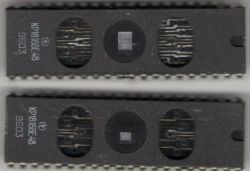
    The Kvantor company also produced other microcircuits in such cases, so I think that it was simply used for cost-saving reasons.

    Chip ??1816??48 in a case with "windows":
    Clock with VFD display IVL1-7/5 based on KR145IK1911 and DS32kHz

    It was simply easier - to use an already used technique than to change the technology for another system.
    Anyway, the investigation is ongoing ;)
  • #10
    Block3r
    Level 14  
    I was intrigued by the described circuit (KR145IK1911) and I would love to build a clock based on it. Unfortunately, the availability of this Soviet technological marvel is minimal :P Where can I get some copies? I haven't found anything in Poland, only eBay and it's a shipment from Russia, so there is currently no option for it to arrive. Maybe there are other, more accessible VFD clocks, also implementing all the functionalities in one chip?
  • #11
    kris8888
    Level 38  
    I think a slightly better effect would be if this glass or plastic dome was made of slightly smoked glass. Green or blue. The readability of the display would also improve during the day.
  • #12
    pawelr98
    Level 39  
    Block3r wrote:
    I was intrigued by the described circuit (KR145IK1911) and I would love to build a clock based on it. Unfortunately, the availability of this Soviet technological marvel is minimal :P Where can I get some copies? I haven't found anything in Poland, only eBay and it's a shipment from Russia, so there is currently no option for it to arrive. Maybe there are other, more accessible VFD clocks, also implementing all the functionalities in one chip?

    The USSR had unusual logic systems, with no counterparts in Western countries. If a friend also takes a look, this system is inserted into the socket "by force" because the pins slightly do not match the spacing of the socket.
    This is due to the fact that the chips in the USSR were produced with a pitch of 2.5mm, not 2.54mm (0.1 inch) as in the West.

    There is no point in playing it, today one microcontroller will serve a colleague more, simpler and cheaper.

    On PIC16F676 I wrote a whole VFD watch with 6 tubes controlled by CD4028 and CD4056. Date handling with leap years also included in the code. The main control system is ?2??641, i.e. 3 x open-collector PNP.

    High-voltage shift register systems for direct control are readily available, so a microcontroller with a small number of pins can be used.
  • #13
    sundayman
    Level 25  
    Quote:
    Where can I get some copies?


    There is a seller (company) from Germany on Ebay.
    Search for "KR145IK1911 vfd nixie clock driver".
    Systems in the version with windows for the price of 9.99 euros + 6 euros shipping.
    I just bought 2 pcs.

    It is worse with IVL1-7/5 displays. There are (even new ones) on Ebay, but the prices are not pleasant. Note: IVL2-7/5 which is slightly cheaper is also much smaller. So the effect will no longer be so attractive.

    Quote:
    There is no point in playing it, today one microcontroller will serve a colleague more, simpler and cheaper.


    But it's not about being "easier and cheaper". It's about being "archaic". This Soviet chip looks perfect for this display.
  • #14
    TechEkspert
    Editor
    Interestingly, VFD was used in a quite modern and mass product - nbox set-top boxes.

    Alphanumeric FVD display: https://www.elektroda.pl/rtvforum/topic3762233.html
    Heavily used set-top boxes showed signs of wear and decreased brightness of VFD displays.

    Why have they been used today?

    It certainly increased the cost, so it could have been about getting an effective appearance of the front panel.
  • #15
    carrot
    Moderator of Cars
    I really like VFD displays, they have their own charm, especially when they have a purple filter installed, which provides a visually pleasing blue color of the displayed characters (which cannot be said about blue LEDs).
    Nice steampunk casing, begging for some brass accent
  • #16
    mkpoz
    Level 10  
    TechEkspert wrote:
    A very interesting idea and an aesthetic and original effect.
    I remember DS32kHz from Dallas / Maxim even before the merger with Analog Devices.

    Where did you buy the DS32kHz?
    Is there anything with similar characteristics to DS32kHz?


    Thanks a lot.
    I bought a DS32kHz here on the lead. Post the best advertisement that you are looking for this arrangement. Someone will surely report.

    Added after 7 [minutes]:

    Block3r wrote:
    I was intrigued by the described circuit (KR145IK1911) and I would love to build a clock based on it. Unfortunately, the availability of this Soviet technological marvel is minimal :P Where can I get some copies? I haven't found anything in Poland, only eBay and it's a shipment from Russia, so there is currently no option for it to arrive. Maybe there are other, more accessible VFD clocks, also implementing all the functionalities in one chip?


    It's hard to get in Poland. The easiest way is on eBay, there is a guy from Germany who has these chips at a very good price - probably about PLN 50.
    Before I started my clock, I looked around a bit and there is nothing "modern" for VFD displays. These Soviet systems are unbeatable, and in addition they are specialized systems, thanks to which it is easy to make your construction.

    Added after 3 [minutes]:

    kris8888 wrote:
    I think a slightly better effect would be if this glass or plastic dome was made of slightly smoked glass. Green or blue. The readability of the display would also improve during the day.


    The design is never so perfect that it cannot be more perfect ;)

    Added after 3 [minutes]:

    pawelr98 wrote:
    The USSR had unusual logic systems, with no counterparts in Western countries. If a friend also takes a look, this system is inserted into the socket "by force" because the pins slightly do not match the spacing of the socket.
    This is due to the fact that the chips in the USSR were produced with a pitch of 2.5mm, not 2.54mm (0.1 inch) as in the West.

    There is no point in playing it, today one microcontroller will serve a colleague more, simpler and cheaper.

    On PIC16F676 I wrote a whole VFD watch with 6 tubes controlled by CD4028 and CD4056. Date handling with leap years also included in the code. The main control system is ?2??641, i.e. 3 x open-collector PNP.

    High-voltage shift register systems for direct control are readily available, so a microcontroller with a small number of pins can be used.


    True, the systems in Comecon often had no counterparts in the West and, in addition, had a slightly different raster (metric, not inch).
    I based my construction on the Soviet system because they are cheap, do not require special skills and are "armored".

    Added after 2 [minutes]:

    sundayman wrote:
    Quote:
    Where can I get some copies?


    There is a seller (company) from Germany on Ebay.
    Search for "KR145IK1911 vfd nixie clock driver".
    Systems in the version with windows for the price of 9.99 euros + 6 euros shipping.
    I just bought 2 pcs.

    It is worse with IVL1-7/5 displays. There are (even new ones) on Ebay, but the prices are not pleasant. Note: IVL2-7/5 which is slightly cheaper is also much smaller. So the effect will no longer be so attractive.

    Quote:
    There is no point in playing it, today one microcontroller will serve a colleague more, simpler and cheaper.


    But it's not about being "easier and cheaper". It's about being "archaic". This Soviet chip looks perfect for this display.


    I used to buy chips from this guy.
    And I completely agree that it's not hard to make something "easier and cheaper". My design was supposed to be "retro" :)

    Added after 1 [minutes]:

    carrot wrote:
    I really like VFD displays, they have their own charm, especially when they have a purple filter installed, which ensures a very visually pleasing blue color of the displayed characters (which cannot be said about blue LEDs).
    Nice steampunk casing, begging for some brass accent


    They have charm :) Hence my post. The circuit used, due to the fact that it is specialized and is ideal for a beginner electronics who wants to have his own design :)
  • #17
    pawelr98
    Level 39  
    TechEkspert wrote:

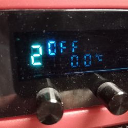
    Heavily used set-top boxes showed signs of wear and decreased brightness of VFD displays.

    It will probably be so light from 11 years of regular use of this Scythe Kaze Master Pro fan controller.
    Clock with VFD display IVL1-7/5 based on KR145IK1911 and DS32kHz

    You can see the uneven burnout of the phosphor, it should also be noted that the green phosphorus has not changed at all, and the blue one has significantly degraded.

    The blue segments are legible but sometimes barely visible.
    It looks worse in real life than in the picture.

    sundayman wrote:

    But it's not about being "easier and cheaper". It's about being "archaic". This Soviet chip looks perfect for this display.

    I would throw archaic drivers and the rest in the normal technique.
    Even a friend can play for sport in making a watch in TTL / CMOS logic with multiplexing. CMOS can easily handle up to 20V, which is more typical for many western and some Soviet of displays is quite sufficient.

    However, if we are talking about Soviet technology.
    I use the ??-3? (IW-3A) tubes that I got together with the whole laminate with drivers.

    Why are these lamps "better"?
    Well, because the glow of each of these lamps is 0.85V (0.7-1V) and, looking at the laminate, they were glowed with direct current at the factory, without any shifting of the glowing potential. With anode and grid at 30V, that 0.85V at the cathode is negligible.

    In the USSR, 4Vac heating was also willingly used, but anode and grid heating was then, for example, 50V. Thus, additional complications with the transfer of the glow potential can be omitted.

    Somehow in the west they didn't come up with such a patent, they stuck to 4Vac and quite low anode and grid voltage.
  • #18
    sundayman
    Level 25  
    Quote:
    Why have they been used today?


    VFD displays are still manufactured and used today.
    Unfortunately, they are expensive - graphic 128x64 is several hundred zlotys.

    And why is it worth using them? Firstly, fantastic resistance to temperatures (especially low temperatures), secondly, excellent contrast, thirdly, speed.
    Actually, only OLED is a competition for VFD. But the wear rate seems to be higher...

    LCD unfortunately does not have a VFD start at low temperatures.
    For more serious devices, they are perfect. Only this price...
  • #19
    TechEkspert
    Editor
    @pawelr98 what modern IC control stages would be a good bridge between a microcontroller and 30V anode voltage?

    Can you post a picture of the original driver board for these VFDs? They surprised me with a series connection of glow.

    As for graphic vfd, you can hunt them at auctions for PLN 50-80, new ones are very expensive ...
  • #20
    pawelr98
    Level 39  
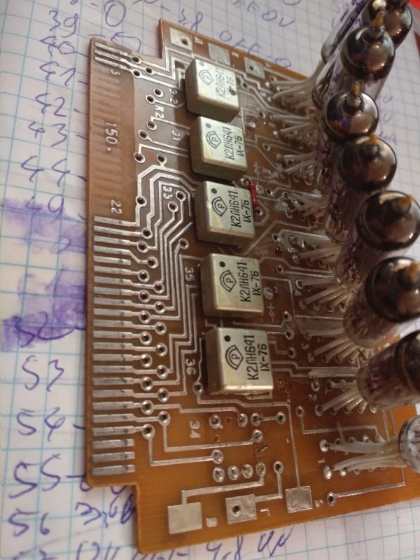
    The connection was in parallel, all filaments between the negative rail and a single pin.

    Clock with VFD display IVL1-7/5 based on KR145IK1911 and DS32kHz

    This is roughly what my controls look like.


    Layout example?
    6C595
    Shift register with open-drain outputs capable of driving up to 33V and 100mA.
  • #21
    Gizmoń
    Level 28  
    tomekptk wrote:
    Those who remember this "system" know that there was simply no (after all, everything was still missing at that time) proper housings, so they were loaded with windows that were supposed to be, for example, for EPROM memory or secret microprocessors to control ballistic missiles


    If it was a replacement as a result of a shortage, then:
    - please show me those EPROMs with two windows
    - the question is, what kind of layout would such two windows have, and those going through the casing?

    Clock with VFD display IVL1-7/5 based on KR145IK1911 and DS32kHz

    These recesses are ordinary technological holes, which certainly served to stiffen the openwork when filling the mold with resin. Why some have it and others don't, I don't know. However, the graphic signs on my and the author's layout indicate the same factory, so either someone there had "takuju idieju" and simply made such forms as more reliable, or they had more sticky resin or less rigid openwork and this forced the use of additional reinforcements.
  • #22
    mkpoz
    Level 10  
    pawelr98 wrote:

    I would throw archaic drivers and the rest in the normal technique.
    Even a friend can play for sport in making a watch in TTL / CMOS logic with multiplexing. CMOS can easily handle up to 20V, which is more typical for many western and some Soviet displays is quite sufficient.

    However, if we are talking about Soviet technology.
    I use the ??-3? (IW-3A) tubes that I got together with the whole laminate with drivers.

    Why are these lamps "better"?
    Well, because the glow of each of these lamps is 0.85V (0.7-1V) and, looking at the laminate, they were glowed with direct current at the factory, without any shifting of the glowing potential. With anode and grid at 30V, that 0.85V at the cathode is negligible.

    In the USSR, 4Vac heating was also willingly used, but anode and grid heating was then, for example, 50V. Thus, additional complications with the transfer of the glow potential can be omitted.

    Somehow in the west they didn't come up with such a patent, they stuck to 4Vac and quite low anode and grid voltage.


    Maybe someday I'll try a different technique.

    As for the durability of these displays, manufacturers most often placed information about the durability of at least 10,000 hours, but in the instructions for such clocks they wrote up to 30,000 hours. However, I believe that if the filament voltage is lowered (as in my design), this time will be significantly longer. My clock has been running for a year now and I don't see any signs of aging of the phosphor.

    I was thinking about the ??-3? (IW-3A) lamps, it is a nice alternative to the ???1-7/5 (IVL1-7/5) and ???2-7/5 (IVL2-7/5) displays, which allows you to extend the range of displayed information e.g. seconds or date.

    Added after 5 [minutes]:

    Gizmoń wrote:
    tomekptk wrote:
    Those who remember this "system" know that there was simply no (after all, everything was still missing at that time) proper housings, so they were loaded with windows that were supposed to be, for example, for EPROM memory or secret microprocessors to control ballistic missiles


    If it was a replacement as a result of a shortage, then:
    - please show me those EPROMs with two windows
    - the question is, what kind of arrangement would such two windows have, and those going through the casing?

    Clock with VFD display IVL1-7/5 based on KR145IK1911 and DS32kHz

    These recesses are ordinary technological holes, which certainly served to stiffen the openwork when filling the mold with resin. Why some have it and others don't, I don't know. However, the graphic signs on my and the author's layout indicate the same factory, so either someone there had "takuju idieju" and simply made such forms as more reliable, or they had more sticky resin or less rigid openwork and this forced the use of additional reinforcements.


    Well, I admit, it's just crazy :) and the factory is actually the same ??????? ?????? (Kvantor Zbarazh).
  • #23
    sundayman
    Level 25  
    Quote:
    freak


    Well, it looks beautiful. What kind of arrangement is this anyway?
    I can't find anything under KP102XA4, KR102XA4, KR102ZA4.

    There can be several rational explanations:

    - access to connections (because they are exposed) from above. But why ?
    - if it was about high currents, then better cooling of the wires. But probably not in this case.
    - a little less used, probably valuable plastic. Well, then it would be worth covering these wires at least thinly.
    - or maybe it was just about "design"? Russians sometimes had such a fantasy...

    Quote:
    to stiffen the openwork


    This is probably the most sensible explanation. But why didn't they do it "normally", like in all other systems? Haven't they done yet?
  • #24
    speedy9
    Helpful for users
    zgierzman wrote:
    I still have some DS32kHz in DIP 14 and SOIC-16 packages that I got as a free sample from Maxim back then.

    I also have two pieces in DIP 14. I just realized that they are probably over 15 years old ... Recently I just pulled one out while making a watch :D I didn't even know it was so expensive now.
    TechEkspert wrote:
    Is there anything with similar characteristics to DS32kHz?

    There is, even a lot, and they are also cheaper, examples: https://www.mouser.pl/c/passive-components/frequency-control-timing-devices/oscillators/tcxo-oscillators/?frequency=32.768%20kHz&product%20type =TCXO
    They are even with better stability.
  • #25
    zgierzman
    Level 31  
    speedy9 wrote:
    They are even with better stability


    Not much... DS32kHz for the temperature range 0°C - 40°C is typically ?2 ppm.
    I'm looking at the link you posted, and only the TG-3541 XA has ?1.9 ppm in the range of 0°C - 50°C

    Of course, for indoor applications there is something "Frequency Tolerance @ 25°C ?3°C ?1.5 ppm", but if the clock can be exposed to external conditions, you will be hard pressed to find something better than the Maxim.
  • #26
    speedy9
    Helpful for users
    zgierzman wrote:
    I'm looking at the link you posted, and only the TG-3541 XA has ?1.9 ppm in the range of 0°C - 50°C

    Yes, this TG is nice, much cheaper and has good stability. Interestingly, it is the cheapest of all from the link.
    At room temperature the ECS-327TXO is also OK with a stability of ?1.5
  • #27
    kris8888
    Level 38  
    sundayman wrote:

    And why is it worth using them? Firstly, fantastic resistance to temperatures (especially low temperatures), secondly, excellent contrast, thirdly, speed.
    Actually, only OLED is a competition for VFD. But the wear rate seems to be higher...

    LCD unfortunately does not have a VFD start at low temperatures.
    For more serious devices, they are perfect. Only this price...

    The advantage of VFD is also that in the dark they do not require any additional backlight, unlike LCD. And besides, they can display various fancy shapes or symbols (created at the production stage of a given VFD), unlike LEDs, which are usually made as simple eight- or fourteen-segment modules.

    I used to like VFDs too. So much so that I collected only VFD-based calculators. What fascinated me about the portable ones was that a miniature transistor converter was used only to generate the anode voltage for the VFD.
  • #28
    Gizmoń
    Level 28  
    sundayman wrote:
    What kind of arrangement is this anyway?
    I can't find anything under KP102XA4, KR102XA4, KR102ZA4.


    Because it is ??1021??4 - the system is not very useful today, because it is a PAL decoder.

    By the way, the design of the pins of these displays from the IWL1 series is interesting. Usually, it is the metal legs that "enter" the vacuum and there somehow combine with the metallization on the glass. It's the other way around here - the metallization goes outside, and the connections with the feet are secured with a glass strip and some kind of resin. This solution is rather delicate and not very resistant to moisture. Of the four IWL1-8/13 displays found in different bushes, none of them have all the connections working, nay! Only in one there is no break in the glow circuit and anything can be lit. For comparison, a VFD with the legs going inside will work even fished out of the river, as long as the legs have not rusted and completely fallen off :D
    I wonder what it looked like historically? Were IWL1 transitional between IW (with wire legs embedded in glass) and IWL2 (with metal legs passing through glass)?
  • #29
    szeryf3
    Level 27  
    @mkpoz clock looks great. Even placing it in glass gives an effect.
    As for getting displays and layouts. This is what you need to watch carefully at the flea market.
  • #30
    sundayman
    Level 25  
    I bought a Soviet Elektronika 6.15 watch for gutting at a price lower than the display itself on Ebay. Of course, the display will be used, but if you get a used copy, it's not a problem.