logo elektroda
logo elektroda
X
logo elektroda

Create Tuya Wi-Fi switch backup - information about connection

flakerazor 171 4
ADVERTISEMENT
Treść została przetłumaczona german » english Zobacz oryginalną wersję tematu
  • #1 21615309
    flakerazor
    Level 2  
    Hello,
    I would like to back up a Tuya Wi-Fi switch, what is the best way to do this?
    Does the bin file show where what is connected?

    Greetings
    AI: Which exact model or version of the Tuya Wi-Fi switch are you talking about?
    Tuya Wi-Fi Smart Circuit Breaker MCB 1P + N 16A with metering
  • ADVERTISEMENT
  • #2 21616823
    p.kaczmarek2
    Moderator Smart Home
    Hello, which Wi-Fi module? Something from the BK7231?

    Have you seen the repository of our flasher?
    https://github.com/openshwprojects/BK7231GUIFlashTool

    The procedure for connecting the UART and ripping and uploading the firmware is also shown on our English language YT: https://www.youtube.com/@elektrodacom

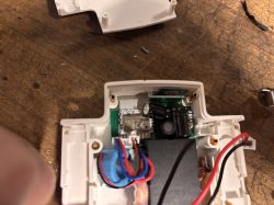
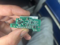
    Please show some pictures from the inside of this device, or at least give some information about what Wi-Fi module you have there. It is difficult to advise more in the dark.
    Helpful post? Buy me a coffee.
  • ADVERTISEMENT
  • #3 21619413
    flakerazor
    Level 2  
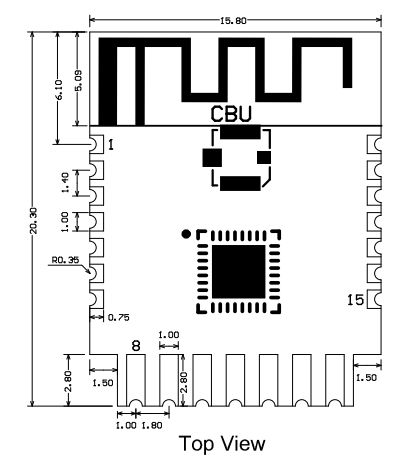
    Wi-Fi module is CBU.

    Create Tuya Wi-Fi switch backup - information about connection Create Tuya Wi-Fi switch backup - information about connection

    Added after 7 [hours] 21 [minutes]:

    Hello, I created a backup today with the Bk7231GUI FlashTool and then flashed it with the latest OpenBeken.
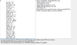
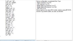
    Reading out which pin does what also worked.
    The only thing I'm missing now is the information on how voltage and current are read out, it didn't read that out.

    Create Tuya Wi-Fi switch backup - information about connection
    Create Tuya Wi-Fi switch backup - information about connection

    Can anyone help me?
  • ADVERTISEMENT
  • #4 21619905
    p.kaczmarek2
    Moderator Smart Home
    Download our flasher, also check out the tutorial (CB2S is similar to CBU).
    https://github.com/openshwprojects/BK7231GUIFlashTool


    .
    Pins:
    CB2S electronic board with clearly marked pins and components. .
    Quote:
    .
    14.
    Pin number . Symbol I/O type Function
    1 1 P14 I/O Common GPIO, which can be reused as SPI_SCK (Correspond to Pin 11 of the IC)
    . 2 P16 I/O Common GPIO, which can be reused as SPI_MOSI (Correspond to Pin 12 of the IC)
    3 P20 I/O Common GPIO (Correspond to Pin 20 of the IC)
    4 P22 I/O Common GPIO (Correspond to Pin 18 of the IC)
    5 5 ADC I/O ADC, which corresponds to P23 on the internal IC (Correspond to Pin 17 of the IC)
    6 RX2 I/O UART_RX2, which corresponds to P1 on the internal IC. (Correspond to Pin 28 of the IC)
    7 TX2 I/O UART_TX2, which is used for outputting logs and corresponds to P0 of the internal IC (Correspond to Pin 29 of the IC)
    8
    8 P8 I/O Support hardware PWM (Correspond to Pin 24 of the IC)
    9 P7 I/O Support hardware PWM (Correspond to Pin 23 of the IC)
    10 P6 I/O Support hardware PWM (Correspond to Pin 22 of the IC)
    11 P26 I/O Support hardware PWM (Correspond to Pin 15 of the IC)
    12 P24 I/O Support hardware PWM (Correspond to Pin 16 of the IC)
    13 GND P Power supply reference ground
    P 3V3 P Power supply 3V3
    15 TX1 I/O UART_TX1, which is used for transmitting user data and corresponds to Pin 27 of the IC. For the MCU solution, please refer to CBx Module.
    . 16 RX1 I/O UART_RX1, which is used for receiving user data and corresponds to Pin 26 of the IC. For the MCU solution, please refer to CBx Module.
    17 . P28 I/O Common GPIO (Correspond to Pin 10 of the IC)
    18 CEN I/O Reset pin, low active (internally pulled high), compatible with other modules (Correspond to Pin 21 of the IC)
    19 P9 I/O Common GPIO (Correspond to Pin 25 of the IC)
    20 P17 I/O Common GPIO, which can be reused as SPI_MISO (Correspond to Pin 14 of the IC)
    . 21 P15 I/O Common GPIO, which can be reused as SPI_CS (Correspond to Pin 13 of the IC)
    Test point point CSN I/O Mode selection pin. If it is connected to the ground before being powered on, enter the firmware test mode. If it is not connected or connected to VCC before being powered on, enter the firmware application mode. Correspond to Pin 19 on the internal IC.
    .
    .
    Helpful post? Buy me a coffee.
ADVERTISEMENT