logo elektroda
logo elektroda
X
logo elektroda

Which RGB ribbon controller for Home Assistant? EC79901 WiFi module firmware change

p.kaczmarek2 564 5
ADVERTISEMENT
Treść została przetłumaczona polish » english Zobacz oryginalną wersję tematu
📢 Listen (AI):
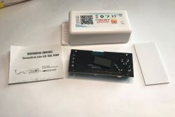
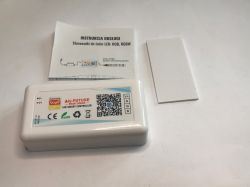
  • Tuya WiFi LED controller with user manual and mounting tape .
    Here's another LED lighting controller offering control via WiFi. This time I'm also changing its firmware at the request of a reader - I'm reprogramming the WiFi module so that this controller can be connected to Home Assistant and controlled locally without the cloud.

    The controller shown here is commercially available under the name EC79901 and is designed for RGB tapes, but after changing the firmware, it can also control three separate single-colour tapes or CW tape (shades of white). It's all up to us.

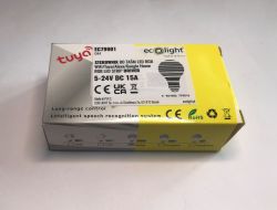
    So let's start with the kit's markings and contents. The manufacturer promises 12-24V DC operation at up to 15A.
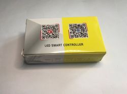
    LED Smart Controller package with two QR codes for Tuya and Smart Life apps Tuya EC79901 LED controller box with EcoLight branding and technical specifications .
    A double-sided adhesive strip for mounting the controller is included.
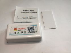
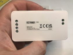
    Tuya LED controller, instruction manual, and mounting tape on white surface LED controller EC79901 held in hand, label with CE and UKCA certifications visible .
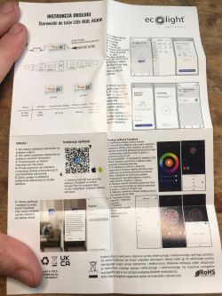
    The manual is in Polish and English:
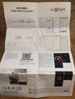
    User manual for LED RGB/RGBW Ecolight controllers laid out on a table EcoLight RGB/RGBW LED controller manual with diagrams, app screenshots, and QR code .
    Pairing with Tuya I skip. Time to change the batch.

    The case is snap-on, it's easy to look inside.
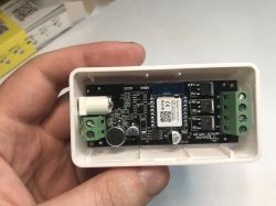
    EC79901 LED controller with open casing showing internal components RGB LED controller with opened case, PCB board and user manual visible .
    The first thing that caught my eye was that through-hole resistor - could it be some quick fixes at the factory?
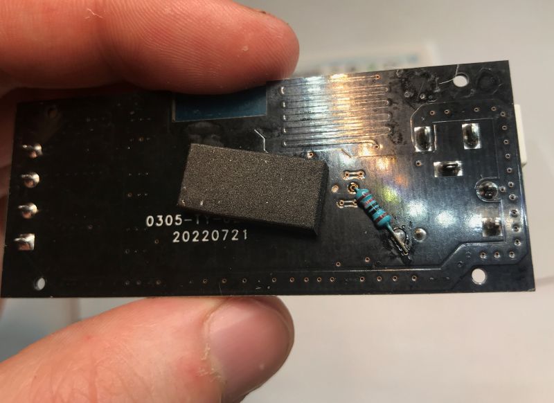
    Close-up of an LED controller PCB with a manually soldered through-hole resistor .
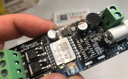
    The construction of the controller is fairly typical. Inside we have a step-down inverter converting these 12V inputs to 3.3V for the WiFi module. I can also see a microphone nearby.
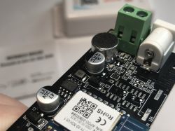
    Close-up of LED controller PCB with CB3S WiFi module, microphone, and power terminals EC79901 LED controller board with CB3S WiFi module and screw terminals visible .
    The inverter used here is the XL1509 3.3 - as the name suggests, 3.3V:
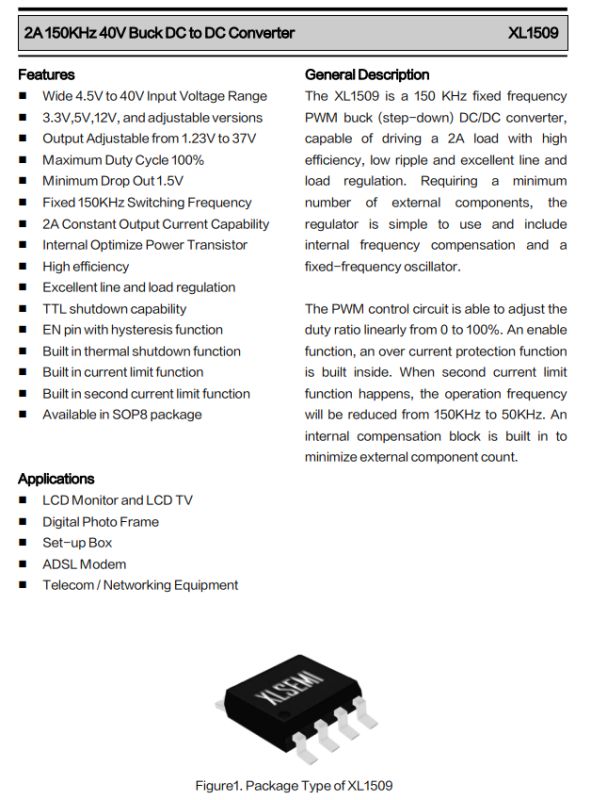
    Technical datasheet of XL1509 buck converter with features and applications .
    The WiFi module itself is CB3S - you can upload a Polish OpenBeken .
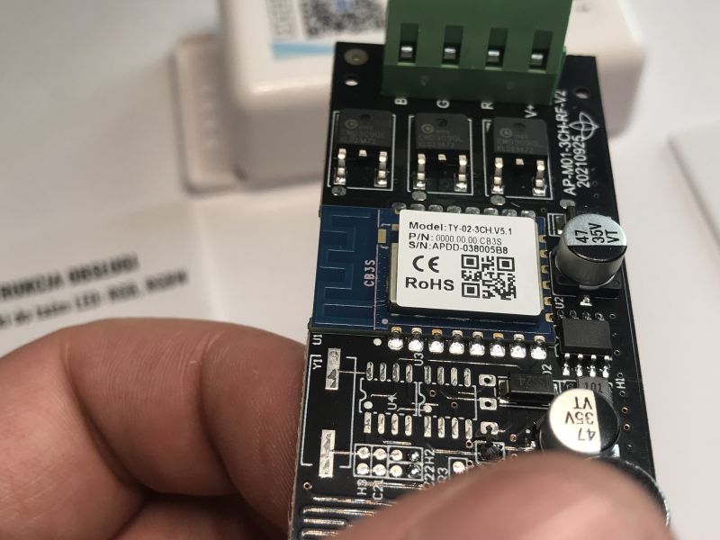
    Close-up of CB3S WiFi module on EC79901 LED controller board .
    PCB designation: AP-M01-3CH-RF-V2 20210925 This RF stands for radio communication, which is not implemented here - the PCB lacks radio components.
    The transistors remain:
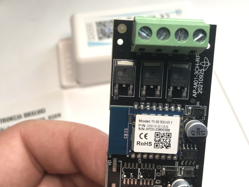
    LED controller module labeled AP-M01-3CH-RF with CB3S WiFi module visible .
    CMD3090L, controlled directly from the GPIO:
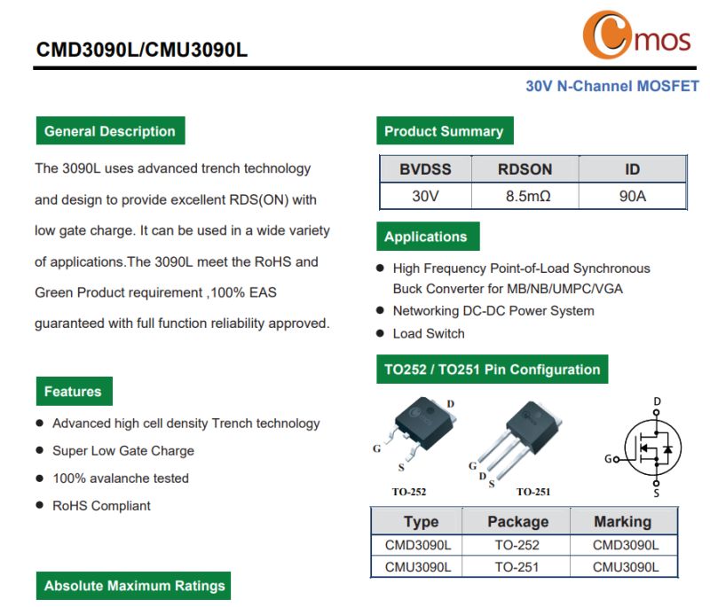
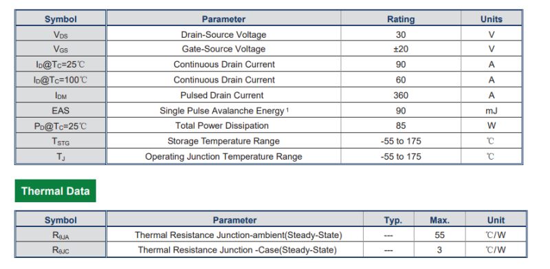
    Datasheet for N-channel MOSFET CMD3090L/CMU3090L with specs and pin layout .
    Table of MOSFET CMD3090L electrical and thermal characteristics. .
    These are indeed better transistors than what I usually find in such products. The drain current is also large and the resistance in the open state is small.

    Now it's time to change the firmware .
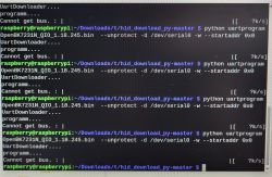
    According to our flasher's instructions, all you need is a USB to UART converter:
    https://github.com/openshwprojects/BK7231GUIFlashTool
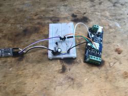
    I took the 3.3V from the LDO on my board, although you could just as well feed from the input from the LED strip.
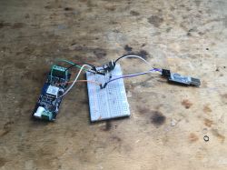
    CB3S LED controller connected to breadboard with USB-UART adapter EC79901 LED controller connected to breadboard and USB-UART adapter .
    Flasher has correctly detected the configurations:
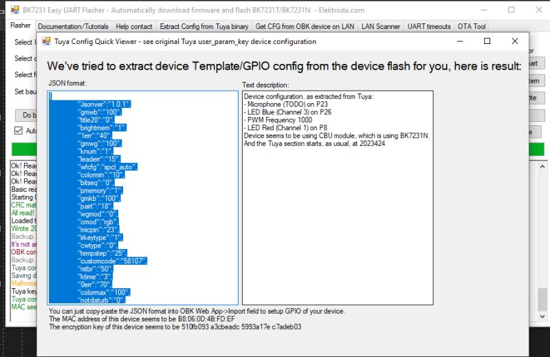
    BK7231 Easy UART Flasher window showing GPIO config of LED controller .
    Verbal description:
    
    Device configuration, as extracted from Tuya: 
    - Microphone (TODO) on P23
    - LED Blue (Channel 3) on P26
    - LED Green (Channel 2) on P24
    - PWM Frequency 1000
    - LED Red (Channel 1) on P8
    Device seems to be using CBU module, which is using BK7231N.
    And the Tuya section starts, as usual, at 2023424
    
    .
    It is also interesting to note that according to the JSON from Tuya, this module identifies itself as a CBU:
    Code: JSON
    Log in, to see the code
    .
    OBK template:
    Code: JSON
    Log in, to see the code
    .
    From now on, you can control the device locally and connect it to the Home Assistant:


    In summary , this was another easily reprogrammable device from China. This time, however, I don't think the rework is complete, as the pushbutton is still missing - fortunately it can be soldered to any free GPIO and OpenBeken will take care of the rest. The pull up resistor is programmable on the CB3S, so just a microswitch between ground and the selected pin is enough and you can already control the device physically too, without WiFi.
    Something similar was shown here: https://www.youtube.com/watch?v=KU0tDwtjfjw
    That's it for today, but which LED strip controllers do you guys use? Would you choose to use a controller as the manufacturer gave it here, i.e. without a button on the housing, fully controlled only by WiFi?

    Cool? Ranking DIY
    Helpful post? Buy me a coffee.
    About Author
    p.kaczmarek2
    Moderator Smart Home
    Offline 
    p.kaczmarek2 wrote 12754 posts with rating 10584, helped 593 times. Been with us since 2014 year.
  • ADVERTISEMENT
  • #2 21624113
    artin.bruyen
    Level 17  
    @p.kaczmarek2
    I have this question. Have you combined with connecting SP107E or SP108E addressable LED drivers under HA? Or even better SP611E?
    I've been thinking for a long time about controlling this other than from a phone and app or remote control, but I have no idea :( .
  • ADVERTISEMENT
  • #3 21624121
    p.kaczmarek2
    Moderator Smart Home
    Do the drivers you're asking about have WiFi, or just Bluetooth?

    If Bluetooth only, I've done little work regarding this, but with colleague @DeDaMrAz we recently tested an ESP32 as a gateway:
    How to connect Sonoff R5 Bluetooth Remote to Home Assitant via ESP32 Tasmota Bluetooth Gateway? .
    Helpful post? Buy me a coffee.
  • ADVERTISEMENT
  • #4 21624418
    artin.bruyen
    Level 17  
    @p.kaczmarek2 One of them has Bluetooth, I think 107, the rest have Wifi.
  • ADVERTISEMENT
  • #5 21624439
    p.kaczmarek2
    Moderator Smart Home
    To judge anything more I need to see pictures of these devices, separately the inside of each, rather it should be easy to look inside and see what WiFi or Bluetooth module is there.
    Helpful post? Buy me a coffee.
  • #6 21624837
    artin.bruyen
    Level 17  
    p.kaczmarek2 wrote:
    To judge anything more I need to see pictures of these devices, separately the inside of each, rather it should be easy to look inside and see what WiFi or Bluetooth module is there.


    You're right. Only at the moment I don't have access, and the photos I once took have gone missing, as has everything else acct. I think these wifi's on the ESP32.
📢 Listen (AI):
ADVERTISEMENT