Basic Information:
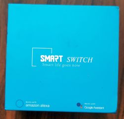
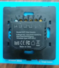
Brand: unbranded, but Tuya based
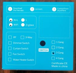
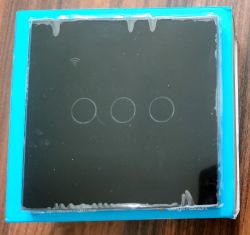
Model: Smart Switch, Touch, Neutral and Live, WiFi + BLE, 3 Gang, Black color
Main chip: CB3S (BK7231N)
Should work with both Google Assistant and Amazon Alexa
SmartLife and/or Tuya Cloud
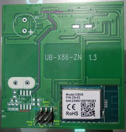
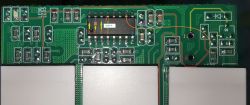
Touch Board: UB-X86-ZN v1.3
Model: 1, 2 or 3 Touch Buttons
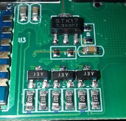
Power Source: STK17 3.3 (low dropout voltage regulator with fixed output at 3.3V), powered by 5V from Relay Board
Touch IC: unknown model (I've looked in many places to find pictures of this chip without its markings deleted; those who look the same and are used for touch, don't have the same GND and VCC pins)
Touch Buttons: all have their own RED and Blue LEDs which are controlled by CB3S module, on the same pin as the corresponding Relay (one pair of Red and Blue LED with a Relay).
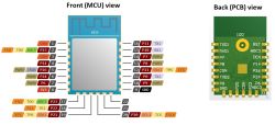
WiFi+BLE & MCU chip: CB3S
There are markings for another chip - U3, probably for the RF433 one, and for a Buzzer (reading about the same type of switches, it seems that the Buzzer used to confirm the setup of the RF Remote Control, but checking the traces on the PCB I see the Buzz's plus pin leads to 3.3V through pads for a resistor, and the minus pin for the Buzz should be connected to a transistor that has one of it's other pads connected to the Touch IC).
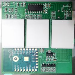
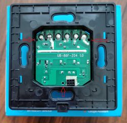
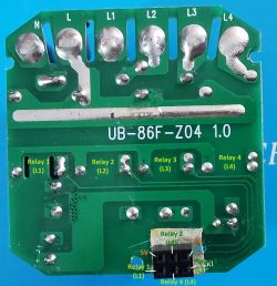
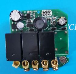
Relay Board: UB-86F-Z04 v1.0
Needs Neutral wire
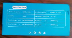
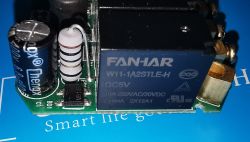
Up to 4 Relays, this has only 3 relays installed (from Fanhar, each of 10A at 250V AC (so 2500VA), but on the case they say each gang can draw up to 500W)
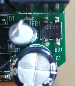
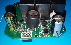
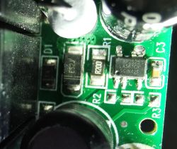
230V mains go trough a 10ohm 1% resistor to the rectifier which is backed by a 6.8uF 400V polarized capacitor, then to a buck converter power supply chip that outputs 5V.
5V is used for Relays and for the power source chip from the Touch Board
Similar product, but with only 1 touch button, from LTC, model LXM170 (white; LXM171 is black): https://www.elektroda.pl/rtvforum/topic4028982.html
Similar product, but with only 2 touch buttons, from LTC, model LXM172(white, LXM173 is black): https://www.elektroda.pl/rtvforum/topic4059302.html
Touch board is configurable depending on the number of touch buttons, by placing / moving resistors in different places.
1 Button version:
Only middle touch button exists which is read by CB3S on pin P10
L1 Relay is controlled by CB3S on pin P6
Corresponds to Channel 1
2 Button version:
Channel 1:
Left touch button is read by CB3S on pin P10
The L1 Relay is controlled by CB3S on pin P6
Channel 2:
Right touch button is read by CB3S on pin P7
The L2 Relay is controlled by CB3S on pin P8
3 Button version:
Channel 1:
Left touch button is read by CB3S on pin P24
The L1 Relay is controlled by CB3S on pin P6
Channel 2:
Middle touch button is read by CB3S on pin P10
L2 Relay is controlled by CB3S on pin P8
Channel 3:
Right touch button is read by CB3S on pin P7
The L3 Relay is controlled by CB3S on pin P9
In all these 3 versions the WiFi LED is controlled by CB3S on pin P26 through a 1k ohm resistor (LED is connected directly to 3.3v)
This touch board also has another trace (connection) from CB3S pin P21 near this WiFi LED, that looks to be for another LED (the other pad is connected to the same 1k ohm resistor that is connected to P26 of CB3S).
Even if RX1 pin of CB3S is connected to the Touch IC, I was able to connect to it using BK7231 GUI Flash Tool v45 and dump the FirmWare.
I'll come back with another post for this.
Brand: unbranded, but Tuya based
Model: Smart Switch, Touch, Neutral and Live, WiFi + BLE, 3 Gang, Black color
Main chip: CB3S (BK7231N)
Should work with both Google Assistant and Amazon Alexa
SmartLife and/or Tuya Cloud


Touch Board: UB-X86-ZN v1.3
Model: 1, 2 or 3 Touch Buttons
Power Source: STK17 3.3 (low dropout voltage regulator with fixed output at 3.3V), powered by 5V from Relay Board
Touch IC: unknown model (I've looked in many places to find pictures of this chip without its markings deleted; those who look the same and are used for touch, don't have the same GND and VCC pins)
Touch Buttons: all have their own RED and Blue LEDs which are controlled by CB3S module, on the same pin as the corresponding Relay (one pair of Red and Blue LED with a Relay).
WiFi+BLE & MCU chip: CB3S
There are markings for another chip - U3, probably for the RF433 one, and for a Buzzer (reading about the same type of switches, it seems that the Buzzer used to confirm the setup of the RF Remote Control, but checking the traces on the PCB I see the Buzz's plus pin leads to 3.3V through pads for a resistor, and the minus pin for the Buzz should be connected to a transistor that has one of it's other pads connected to the Touch IC).


Relay Board: UB-86F-Z04 v1.0
Needs Neutral wire
Up to 4 Relays, this has only 3 relays installed (from Fanhar, each of 10A at 250V AC (so 2500VA), but on the case they say each gang can draw up to 500W)
230V mains go trough a 10ohm 1% resistor to the rectifier which is backed by a 6.8uF 400V polarized capacitor, then to a buck converter power supply chip that outputs 5V.
5V is used for Relays and for the power source chip from the Touch Board


Similar product, but with only 1 touch button, from LTC, model LXM170 (white; LXM171 is black): https://www.elektroda.pl/rtvforum/topic4028982.html
Similar product, but with only 2 touch buttons, from LTC, model LXM172(white, LXM173 is black): https://www.elektroda.pl/rtvforum/topic4059302.html
Touch board is configurable depending on the number of touch buttons, by placing / moving resistors in different places.
1 Button version:
Only middle touch button exists which is read by CB3S on pin P10
L1 Relay is controlled by CB3S on pin P6
Corresponds to Channel 1
2 Button version:
Channel 1:
Left touch button is read by CB3S on pin P10
The L1 Relay is controlled by CB3S on pin P6
Channel 2:
Right touch button is read by CB3S on pin P7
The L2 Relay is controlled by CB3S on pin P8
3 Button version:
Channel 1:
Left touch button is read by CB3S on pin P24
The L1 Relay is controlled by CB3S on pin P6
Channel 2:
Middle touch button is read by CB3S on pin P10
L2 Relay is controlled by CB3S on pin P8
Channel 3:
Right touch button is read by CB3S on pin P7
The L3 Relay is controlled by CB3S on pin P9
In all these 3 versions the WiFi LED is controlled by CB3S on pin P26 through a 1k ohm resistor (LED is connected directly to 3.3v)
This touch board also has another trace (connection) from CB3S pin P21 near this WiFi LED, that looks to be for another LED (the other pad is connected to the same 1k ohm resistor that is connected to P26 of CB3S).
Even if RX1 pin of CB3S is connected to the Touch IC, I was able to connect to it using BK7231 GUI Flash Tool v45 and dump the FirmWare.
I'll come back with another post for this.


