logo elektroda
logo elektroda
X
logo elektroda

Flashing RAINPOINT WiFi Watering System (CB3S) with CH340: Getting Bus Failed

roxyamaha 360 11
ADVERTISEMENT
  • #1 21631746
    roxyamaha
    Level 3  
    I want to flash my RAINPOINT WiFi Automatic Watering System which uses CB3S chip with https://github.com/openshwprojects/BK7231GUIFlashTool by using CH340 board but I'm getting error - Getting bus failed.

    I believe I'm having problem with putting it in flash mode. I tried several methods like:
    - quick re-connect of 3v3 after I hit flash firmware button
    - quick connect both CEN1 or CEN2 pins to GND pin
    - quick connect pin 6 (IO0) to GND
    - tried all port speeds

    TX and RX are swapped, and I don't have any other idea what to do. Seems like I'm making obvious and simple mistake, but can't find it. I flashed many Sonoff and Shelly devices with Tasmota so I'm familiar how things work is basic simple way, but I can say I'm still beginner.
    Let me know what's the case here, please.

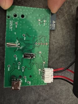
    This is how I did connect CB3S pins to my CH340 board.
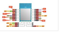
    CB3S module pin diagram showing TX, RX, GND, IO0, 3V3, and CEN labels

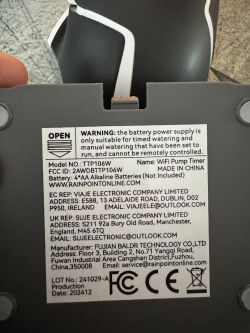
    Technical label on the back of a WiFi Pump Timer device, model TTP106W
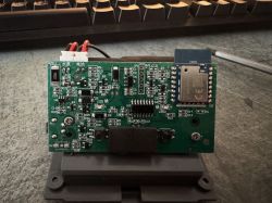
    CB3S module on a PCB with 3.3V power connected and visible electrical components
    PCB board with CB3S module showing RX, TX, GND, and 3V3 pin labels
    AI: Can you provide a detailed description or diagram of how you connected the CB3S pins to your CH340 board (including which pins go to TX, RX, 3v3, GND, and any others)?
    Provided, check original post.
    AI: How are you powering the CB3S during flashing—are you using the CH340's 3.3V output, an external power supply, or both?
    I'm using CH340 3.3 output, tested with multimeter and it gives 3.34 volts
  • ADVERTISEMENT
  • #2 21631891
    p.kaczmarek2
    Moderator Smart Home
    That's certainly an interesting device, I would like to get this running for you. Obviously, the first step is flashing, but as you already noticed, there is some issue.

    This is most likely because your device is using TuyaMCU and has extra MCU connected to CB3S via the same UART port which is used for flashing.

    Long story short, you will probably need to remove this MCU first or cut RX/TX traces or desolder CB3S or try to put MCU into the reset mode (if datasheet is available).

    Still, before doing any actions, I would recommend you to check out our TuyaMCU guide here:
    TuyaMCU flashing, setup and configuration guide - configure dpIDs for Home Assistant

    Futhermore, we will need to know what kind of TuyaMCU is that. Is this battery powered, so TuyaMCU+tmSensor? Or is it powered all the time, so classic, vanilla TuyaMCU?

    Of course, remember to take 2MB backup of flash first.
    Helpful post? Buy me a coffee.
  • ADVERTISEMENT
  • ADVERTISEMENT
  • #4 21631958
    roxyamaha
    Level 3  
    Thank you!

    Device can be powered by 4 AA batteries or can also be powered all the time through power adapter.

    I have tested TX and RX with multimeter to see if any connection exists towards the chip in the middle of picture, but none of the pins are connected.
    Any other proposal how to check?
  • ADVERTISEMENT
  • Helpful post
    #5 21632090
    alleywayapps
    Level 7  
    I did mine using minicom from Linux, setting baud rate to 9600

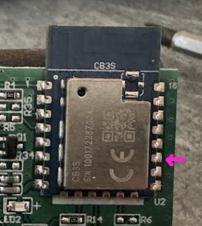
    Can you try just touching the RX of your UART device to the TX2 with nothing else connected, then plug the USB power to the RainPoint board?
    This just to make "first contact" - you should be able to see a bit of logging.

    I flashed mine simply by holding the leads to the module with steady hands...

    Close-up of the CB3S module on a circuit board with one pin marked by a pink arrow.[/img]
  • #6 21632212
    roxyamaha
    Level 3  
    I got this when I connected TX2 from Rainpoint board to RX on CH340 device. But I had to connect GND as well.

    I was using baud | 115200 8N1
    [08-11 18:01:55 ty E][lr:0x7370d] dp 107 data invalid 142612
    [08-11 18:01:56 ty E][lr:0x7370d] dp 107 data invalid 142612
    [08-11 18:01:57 ty E][lr:0x7370d] dp 107 data invalid 142611
    [08-11 18:01:58 ty E][lr:0x7370d] dp 107 data invalid 142611
    [08-11 18:01:59 ty E][lr:0x7370d] dp 107 data invalid 142611
    [08-11 18:02:00 ty E][lr:0x7370d] dp 107 data invalid 142611
    [08-11 18:02:01 ty E][lr:0x7370d] dp 107 data invalid 142611
    [08-11 18:02:02 ty E][lr:0x7370d] dp 107 data invalid 142611
    [08-11 18:02:03 ty E][lr:0x7370d] dp 107 data invalid 142611
    [08-11 18:02:04 ty E][lr:0x7370d] dp 107 data invalid 142611
    [08-11 18:02:05 ty E][lr:0x7370d] dp 107 data invalid 142611
    [08-11 18:02:06 ty E][lr:0x7370d] dp 107 data invalid 142611
    [08-11 18:02:07 ty E][lr:0x7370d] dp 107 data invalid 142611


    While I used 9600 rate, I got weird letters:
    
    ?N 
        ??N 
            ??8!
                ?


    Which pins did you use to flash it?
    - GND to GND
    - RX to TX
    - TX to RX
    - 3v3 to 3v3
    - anything else like from here GND to RST or IO0?
    - https://templates.blakadder.com/rainpoint_TTP106W.html -> https://templates.blakadder.com/assets/device_images/rainpoint_TTP106W_pcb.webp
  • Helpful post
    #7 21632237
    alleywayapps
    Level 7  
    Ah yes, you're right on the baud.

    I didn't need to do GND to RST. Not sure what IO0 is.

    I don't think I even connected 3v3. I only used GND, RX and TX while flashing and the power from USB.

    And it was either CEN1 or CEN3 that you have to do a short touch to from....somewhere...GND?

    Also...I did a backup of the orig firmware first. I did it twice out of paranoia.

    And then just do a straight write of Openbeken.
  • #8 21632249
    roxyamaha
    Level 3  
    Flash worked!

    I think the main catch was to use power from USB instead of 3v3 from CH340 adapter, but I'm not 100% sure as I also did GND to RST as per these docs https://templates.blakadder.com/assets/device_images/rainpoint_TTP106W_pcb.webp

    Now I have to configure PINs.

    MQTT works and I got it in my HA.

    Any suggestion how proceed and what to configure, did you follow this https://templates.blakadder.com/rainpoint_TTP106W.html ?
  • Helpful post
    #9 21632295
    alleywayapps
    Level 7  
    Glad it worked!

    Yeah, that's the thing that threw me for a loop - you don't configure pins.

    Create an autoexec.bat - just copy what I have here in this post to get started:

    >>21630066
  • #10 21632704
    roxyamaha
    Level 3  
    Okay, script worked and I got Pump mode, Watering Duration, Frequency and Fallback.
    However these entities are marked as unavailable in HA. Now I have two MQTT devices, one for actual device and second for Watering Duration with two sensors marked as unavailable.

    If I change values and press pump mode, it won't turn on. Only with original 100, 48, 100 values.

    Need to play around and see what's the catch, but let me know if I'm making some obvious mistake.


    EDIT: Also, how to remove Toggle and Set buttons? I removed script, but they are still there.

    EDIT2: I used template from here https://openbekeniot.github.io/webapp/devicesList.html and imported + rebooted but nothing changes. Modules are all at 0.
  • #11 21632753
    alleywayapps
    Level 7  
    Two quick things:
    The template that someone added is less of actual configuration as we’re not configuring pins like a normal situation.
    Instead the cb3s module communicates to the MCU.
    Also, if you launch the config app from the web console, you’ll notice the tuya mcu config. The values of TextField, ReadOnly, etc. are set from having previously run the script,

    Question though: did you actually get the pump to run from the toggle? It should have worked.


    I think the only thing you’re missing is setting some flags in the config … I’m away from my desk and will be traveling over next days..
  • #12 21634132
    roxyamaha
    Level 3  
    Toggle through web works, but on HA end pump and duration entities are not available.

    If you don't forget, let me know what I need to configure once you get back. Thanks!

Topic summary

The discussion addresses flashing the RAINPOINT WiFi Automatic Watering System using a CB3S chip with a CH340 USB-to-serial adapter and the BK7231GUIFlashTool. The main issue encountered was the "Getting bus failed" error, likely due to difficulty entering flash mode. Various methods to trigger flash mode were attempted, including toggling 3.3V power, grounding CEN1/CEN2 pins, and connecting IO0 to ground, but none succeeded initially. It was suggested that the device uses a TuyaMCU co-processor communicating via UART, which may interfere with flashing. Solutions include removing or resetting the secondary MCU or cutting RX/TX traces. Testing UART communication with minimal connections and correct baud rate (115200) revealed invalid data errors, indicating communication issues. The breakthrough came by powering the device from USB instead of the CH340 3.3V line and grounding the RST pin, enabling successful flashing of OpenBeken firmware. Post-flash, MQTT integration with Home Assistant was confirmed. Configuration involves creating an autoexec.bat script rather than manual pin setup. References to TuyaMCU flashing guides and Rainpoint TTP106W device documentation were provided for further configuration details.
Summary generated by the language model.
ADVERTISEMENT