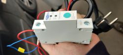
TOMZN 1P 63A Circuit Breaker Power Monitoring DIN Relay
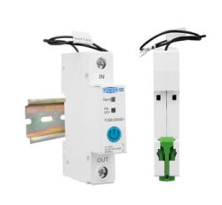

Few days ago I received this Breaking hoping simple installation of Tasmota firmware
https://templates.blakadder.com/tomzn_TOB8-63WiFi.html
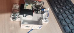
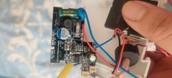
During teardown I found completely different platform, looks like it contains
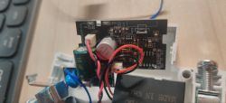
ptblu-w motherboard with BL602 chip
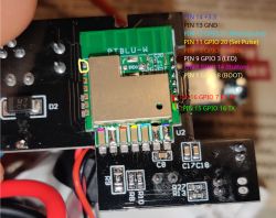
After tracing path using multimeter I found this pins layout.
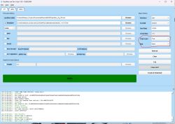
Using firmware tool and BOOT pin (with 10k resistor connected to 3.3V) I successfully flashed OpenBL602_1.18.164.bin image, after firmware I connect device to my WiFi.
But during testing pins layout I found that no pins react to high signal. I tried filling config, I tried GPIO internal tool, no pins even WiFi and power LED are affected by high level
AI: Can you share more details about how you flashed the OpenBL602_1.18.164.bin firmware—what tool and steps did you use, and did you see any errors during the process?
No error during firmware,
AI: Which pins did you test for hi signal, and do you have a pinout diagram or list of the pin numbers/names you tried?
I test all pins followed multimeter traced path
Added after 4 [hours] 26 [minutes]:
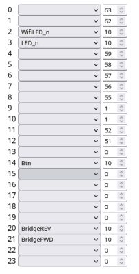
ok looks like i find issues with this this device, i wrong connect Phase and zero wire. so at this moment i successfully find and setup power and wifi led. and using GPIO doctor find BiStable Relay pins. its turnON and turnOFF without any problem, but how to configure bitsable relay in pins configuration menu? BridgeFWD BridgeREV only setup voltage to both pins
Added after 1 [hours] 12 [minutes]:
looks like my i don't have activated BridgeDriver how i can activate this or i need recompile image?

Info:MAIN:Driver Bridge is not known in this build.


Few days ago I received this Breaking hoping simple installation of Tasmota firmware
https://templates.blakadder.com/tomzn_TOB8-63WiFi.html
During teardown I found completely different platform, looks like it contains
ptblu-w motherboard with BL602 chip
After tracing path using multimeter I found this pins layout.

Using firmware tool and BOOT pin (with 10k resistor connected to 3.3V) I successfully flashed OpenBL602_1.18.164.bin image, after firmware I connect device to my WiFi.
But during testing pins layout I found that no pins react to high signal. I tried filling config, I tried GPIO internal tool, no pins even WiFi and power LED are affected by high level
AI: Can you share more details about how you flashed the OpenBL602_1.18.164.bin firmware—what tool and steps did you use, and did you see any errors during the process?
No error during firmware,
AI: Which pins did you test for hi signal, and do you have a pinout diagram or list of the pin numbers/names you tried?
I test all pins followed multimeter traced path
Added after 4 [hours] 26 [minutes]:
ok looks like i find issues with this this device, i wrong connect Phase and zero wire. so at this moment i successfully find and setup power and wifi led. and using GPIO doctor find BiStable Relay pins. its turnON and turnOFF without any problem, but how to configure bitsable relay in pins configuration menu? BridgeFWD BridgeREV only setup voltage to both pins
Added after 1 [hours] 12 [minutes]:
looks like my i don't have activated BridgeDriver how i can activate this or i need recompile image?

Info:MAIN:Driver Bridge is not known in this build.


