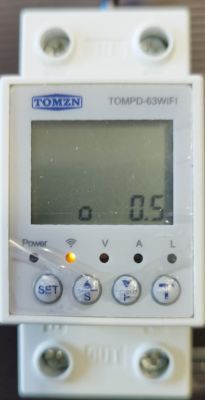
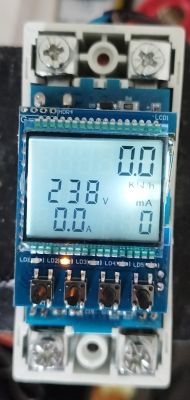
A few days ago I received this device from Aliexpress Link:
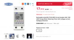
The device is similar to others already treated here, for example Tomzn TOML-VA 63A and Earu EAMPDW-TY63, and also TOMPD-63LW mentioned in the title, although the latter is more complete and cuts both line and neutral.
But, despite the external similarities and in functionality, I see from the teardowns that they are different, so I think it's justified to create a new thread. Apart from this, is a good opportunity to put into practice the tutorial I wrote about extracting DpIDs and try to make it work with OBK starting from zero.
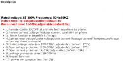
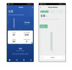
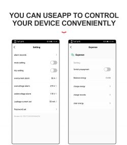
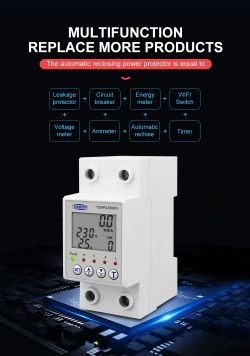
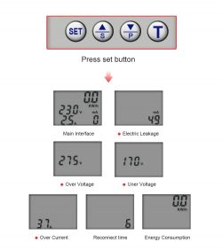
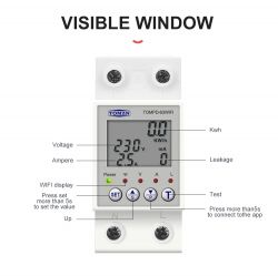
So let's start with some photos from the advertisement in Aliexpress, just in case the previous link gets broken:
Now the printed manual that came with the device:
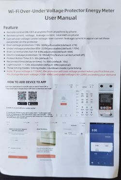
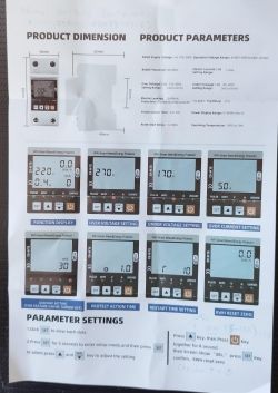
You can already see some differences between the settings in the advertisement and those in the manual. The real thing also included another setting "t" (see next pictures), that can be set to "on" or to a number between 5 and 120.
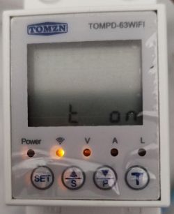
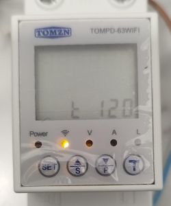
I haven't been able to deduct what is this setting for.
Now, some photos of the teardown:
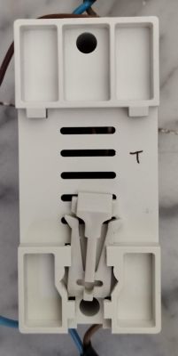
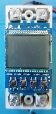
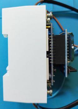
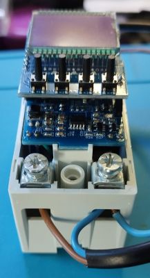
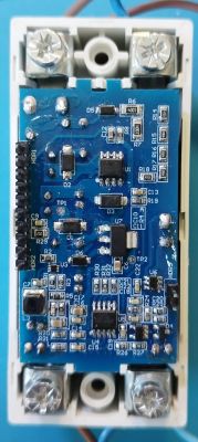

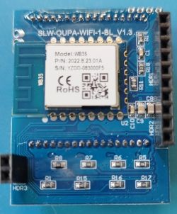
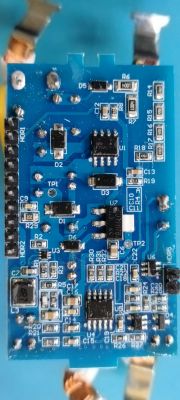
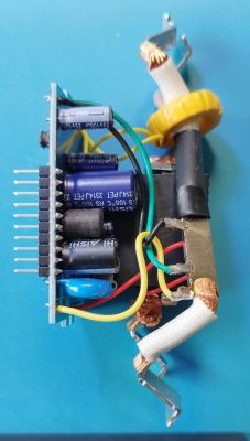
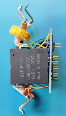
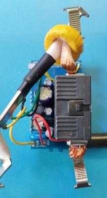
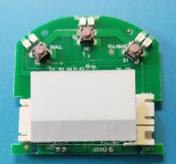
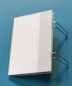
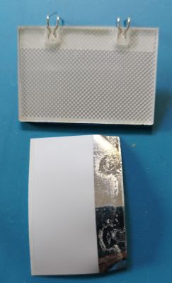
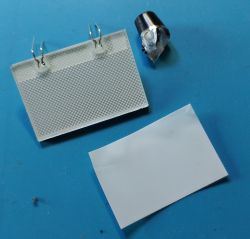
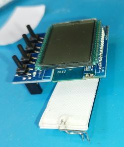
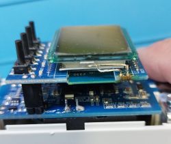
Opening the device is very easy: just unfasten the two screws in the holes of the first photo (after pushing apart the lower side lock). It's well constructed; there are two PCBs: the bigger one supports the relay (latching type, no need to keep the coil energized to set it on), the components for the power supply (12V output for the relay and two 3.3V outputs, one with a linear regulator from 12V and the other one with a switch mode one), and the energy metering chip BL0942 (attached English datasheet). The smaller PCB has the LCD screen, push buttons, the Tuya MCU (behind the LCD screen), and the WB3S WiFi module.
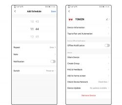
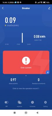
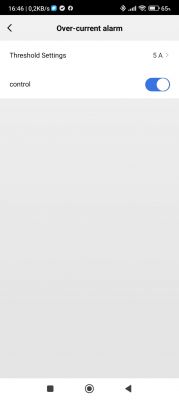
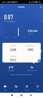
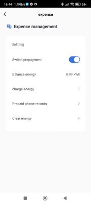
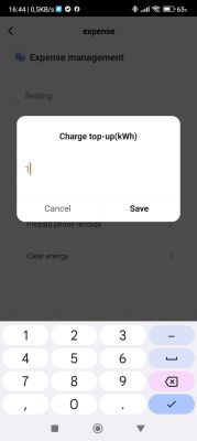
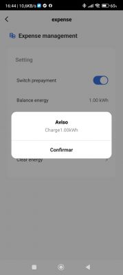
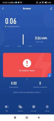
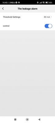
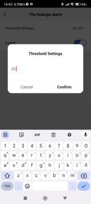
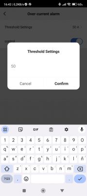
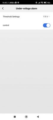
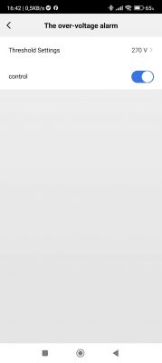
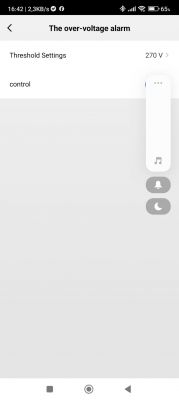
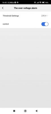
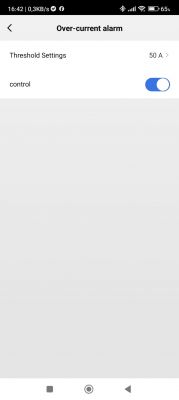
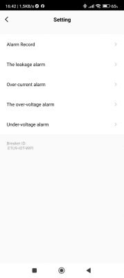
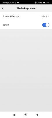
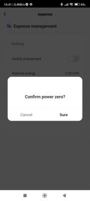
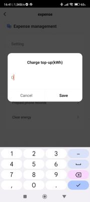
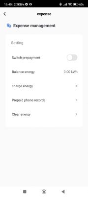
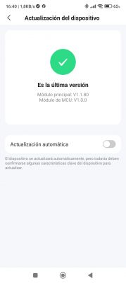
Also, here are some screenshots of the Tuya App; you can see there are also differences with the ones from the advertisement:
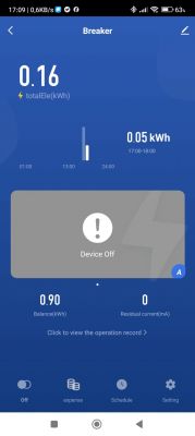
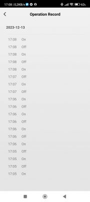

Now, let's start with the DpID identification process, which should be done before flashing OBK, as we need to access the device from Tuya's developer website. Following the first process in the tutorial, we get this:
The same info, written as a list:
We can see that there are a total of 13 DpIDs.
Now, jumping to the last method in the tutorial (signaled with [*]) and, after processing the Json as instructed there, we get:
Where, besides the DpID numbers, we have a more complete description of each of them. With this info in hand we will be able to configure OBK so now we can proceed with flashing.
To flash it with OBK, after unplugging the smaller board from the bigger one, is enough to solder just two wires to the RX and TX pads, as Vcc and Gnd can be connected to the header:
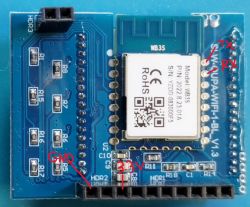
I didn't need to cut any traces to flash OBK as the Tuya MCU doesn't seem to interfere with the process (in principle, it should be shut off, as it gets the power from a different pin in the header). To avoid problems, I only connect TX, RX, and GND to the serial to USB adapter, and connect Vcc just after hitting the corresponding key to start flashing in BK7231Flasher.
Once flashed, we can connect our PC or phone to the access point provided by OBK and navigate to 192.168.4.1, where we configure SSID and password for our local WiFi. After rebooting, we have to find in our router the IP assigned to the device and access it with a browser to continue with the configuration. I first configured MQTT and then, by navigating "Launch web application" -> "Filesystem" -> "Create file" I created "autoexec.bat" with the following contents:
Let's explain briefly the contents: The first lines come from similar devices and are there to start the TuyaMCU driver and simulate the connection to the cloud. I commented out the NTP driver, as it doesn't seem to be necessary. The last line also comes from similar devices and, as I understand, is there to force the MCU to send the state periodically.
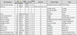
The lines in between correspond to the previously identified DpIDs, linking them to a channel and setting the channel type accordingly. To make things clearer, I preferred to assign channels with the same number as the DpIDs where possible. I also wrote the following table in Excel to help keep things clear, but it's not really necessary:
After saving the autoexec and rebooting the configuration is finished and we can start using the device with OBK:
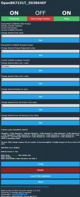
In practice, it's not really needed to have so much info, so you can comment out or delete the corresponding lines in the autoexec.bat to eliminate the variables of less interest. Also, some of them don't work as expected (for example, Alarm set 2 doesn't show well, probably because it's too long), but I hope @p.kaczmarek2 will be correcting this in future versions.
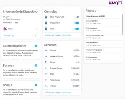
Also, after going to "Config" -> "Home Assistant configuration" and hitting "Start Home Assistant Discovery", we can also control the device from Home Assistant:
And that's all for now! It's a long post and I hope I haven't bored you too much, but I think it is better to give as many details as possible for the most novices; the most experienced just can pass over them quickly
EDIT: corrected label from "Clear Prepayment" to "Clear Energy Counters", as this is what DpID 12 does (thanks, @AngelOf Death)
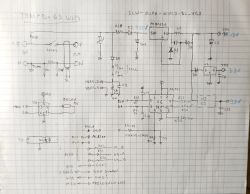
EDIT: Adding schematic:

The device is similar to others already treated here, for example Tomzn TOML-VA 63A and Earu EAMPDW-TY63, and also TOMPD-63LW mentioned in the title, although the latter is more complete and cuts both line and neutral.
But, despite the external similarities and in functionality, I see from the teardowns that they are different, so I think it's justified to create a new thread. Apart from this, is a good opportunity to put into practice the tutorial I wrote about extracting DpIDs and try to make it work with OBK starting from zero.
So let's start with some photos from the advertisement in Aliexpress, just in case the previous link gets broken:


Now the printed manual that came with the device:


You can already see some differences between the settings in the advertisement and those in the manual. The real thing also included another setting "t" (see next pictures), that can be set to "on" or to a number between 5 and 120.


I haven't been able to deduct what is this setting for.
Now, some photos of the teardown:


Opening the device is very easy: just unfasten the two screws in the holes of the first photo (after pushing apart the lower side lock). It's well constructed; there are two PCBs: the bigger one supports the relay (latching type, no need to keep the coil energized to set it on), the components for the power supply (12V output for the relay and two 3.3V outputs, one with a linear regulator from 12V and the other one with a switch mode one), and the energy metering chip BL0942 (attached English datasheet). The smaller PCB has the LCD screen, push buttons, the Tuya MCU (behind the LCD screen), and the WB3S WiFi module.
Also, here are some screenshots of the Tuya App; you can see there are also differences with the ones from the advertisement:


Now, let's start with the DpID identification process, which should be done before flashing OBK, as we need to access the device from Tuya's developer website. Following the first process in the tutorial, we get this:
{"1":"Total forward energy","6":"Phase A","9":"Fault","11":"Switch prepayment","12":"Clear energy","13":"Balance energy","14":"charge energy","15":"Leakage current","16":"Switch","17":"Alarm set1","18":"Alarm set2","19":"Breaker id","104":"Over Vol Protect Time","105":"Over Vol Recovery Time"}The same info, written as a list:
"1":"Total forward energy",
"6":"Phase A",
"9":"Fault",
"11":"Switch prepayment",
"12":"Clear energy",
"13":"Balance energy",
"14":"charge energy",
"15":"Leakage current",
"16":"Switch",
"17":"Alarm set1",
"18":"Alarm set2",
"19":"Breaker id",
"104":"Over Vol Protect Time",
"105":"Over Vol Recovery Time"
We can see that there are a total of 13 DpIDs.
Now, jumping to the last method in the tutorial (signaled with [*]) and, after processing the Json as instructed there, we get:
Code: JSON
Where, besides the DpID numbers, we have a more complete description of each of them. With this info in hand we will be able to configure OBK so now we can proceed with flashing.
To flash it with OBK, after unplugging the smaller board from the bigger one, is enough to solder just two wires to the RX and TX pads, as Vcc and Gnd can be connected to the header:

I didn't need to cut any traces to flash OBK as the Tuya MCU doesn't seem to interfere with the process (in principle, it should be shut off, as it gets the power from a different pin in the header). To avoid problems, I only connect TX, RX, and GND to the serial to USB adapter, and connect Vcc just after hitting the corresponding key to start flashing in BK7231Flasher.
Once flashed, we can connect our PC or phone to the access point provided by OBK and navigate to 192.168.4.1, where we configure SSID and password for our local WiFi. After rebooting, we have to find in our router the IP assigned to the device and access it with a browser to continue with the configuration. I first configured MQTT and then, by navigating "Launch web application" -> "Filesystem" -> "Create file" I created "autoexec.bat" with the following contents:
Code: Java
Let's explain briefly the contents: The first lines come from similar devices and are there to start the TuyaMCU driver and simulate the connection to the cloud. I commented out the NTP driver, as it doesn't seem to be necessary. The last line also comes from similar devices and, as I understand, is there to force the MCU to send the state periodically.
The lines in between correspond to the previously identified DpIDs, linking them to a channel and setting the channel type accordingly. To make things clearer, I preferred to assign channels with the same number as the DpIDs where possible. I also wrote the following table in Excel to help keep things clear, but it's not really necessary:

After saving the autoexec and rebooting the configuration is finished and we can start using the device with OBK:

In practice, it's not really needed to have so much info, so you can comment out or delete the corresponding lines in the autoexec.bat to eliminate the variables of less interest. Also, some of them don't work as expected (for example, Alarm set 2 doesn't show well, probably because it's too long), but I hope @p.kaczmarek2 will be correcting this in future versions.
Also, after going to "Config" -> "Home Assistant configuration" and hitting "Start Home Assistant Discovery", we can also control the device from Home Assistant:

And that's all for now! It's a long post and I hope I haven't bored you too much, but I think it is better to give as many details as possible for the most novices; the most experienced just can pass over them quickly
EDIT: corrected label from "Clear Prepayment" to "Clear Energy Counters", as this is what DpID 12 does (thanks, @AngelOf Death)
EDIT: Adding schematic:

Cool? Ranking DIY


