I bought this Tuya S06Pro (Smart IR remote control with temperature and humidity sensors) from Aliexpress:
https://www.aliexpress.com/item/1005006286419043.html
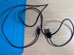
I expected a micro-usb connection, but a USB-C cable was included (no power supply).
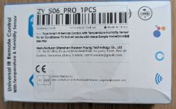
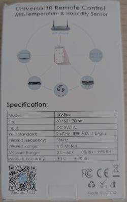

I tried to use `tuya-cloudcutter` but none of the Tuya Generic IR devices worked. I decided to open the case.
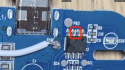
It contains a CB3S, _not_ a WB3S like in this post: https://www.elektroda.com/rtvforum/topic3926882.html#21344074 The pins can be seen here: https://docs.libretiny.eu/boards/cb3s/ The board is labelled `S06ProT-T-CB3S_V1.1: 2025-06-20`
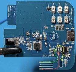
I tried to use the front soldier pads. I soldered GND, 3V3, TXD and RXD, which I connected to a USB-to-TTL.
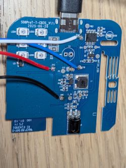
I tried to read the firmware by running `ltchiptool --timed --verbose flash info beken-7231n --timeout 10`. The command fails to connect though. Here are the logs:
I tried to short the CEN pin on the CB3S with the ground while the tool `ltchiptool` was showing the line `In order to do that, you need to bridge CEN pin to GND with a wire.`, but it didn't change anything.
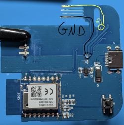
I then decided to try to solder directly on the CB3S module instead:
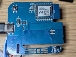

I ran the same `ltchiptool` command as above, even trying to short CEN-GND, but I got the exact same result: The tool cannot connect to the CB3S module.
Am I doing something wrong? I'm out of ideas to try...
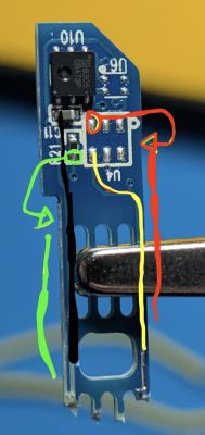
Note 1: The PCB has a small "extending arm" which I believe are the temperature and humidity sensors (see bottom right of the back picture where we see the CB3S module). It's probably on this "arm" to isolate it thermally from the rest (that's my guess). This arm is really fragile! Be careful! I unfortunately broke it when connecting the USB-C cable. I only see two copper lanes going to the sensors, so maybe I could soldier some kind of bridge, but if I can't flash anything on this I won't be using it anyway...
Note 2: My goal is to integrate this into Home Assistant, ideally using ESPHome on it. I want to be able to control my heat pumps' wall units.
Thank you for any help!
https://www.aliexpress.com/item/1005006286419043.html
I expected a micro-usb connection, but a USB-C cable was included (no power supply).


I tried to use `tuya-cloudcutter` but none of the Tuya Generic IR devices worked. I decided to open the case.
It contains a CB3S, _not_ a WB3S like in this post: https://www.elektroda.com/rtvforum/topic3926882.html#21344074 The pins can be seen here: https://docs.libretiny.eu/boards/cb3s/ The board is labelled `S06ProT-T-CB3S_V1.1: 2025-06-20`
I tried to use the front soldier pads. I soldered GND, 3V3, TXD and RXD, which I connected to a USB-to-TTL.

I tried to read the firmware by running `ltchiptool --timed --verbose flash info beken-7231n --timeout 10`. The command fails to connect though. Here are the logs:
❯ ltchiptool --timed --verbose flash info beken-7231n --timeout 10
D [      0.001] (+0.001s) Found Local data snapshot (v1.9.1) - .venv/lib/python3.12/site-packages/ltchiptool
I [      0.002] (+0.000s) Available COM ports:
I [      0.005] (+0.004s) |-- cu.usbserial-1110 - USB2.0-Serial - None (1A86/7523)
I [      0.005] (+0.000s) |   |-- Selecting this port. To override, use -d/--device
I [      0.005] (+0.000s) |-- cu.debug-console - n/a
I [      0.005] (+0.000s) |-- cu.wlan-debug - n/a
I [      0.021] (+0.016s) Connecting to 'Beken 7231N' on /dev/cu.usbserial-1110 @ 115200
D [      0.021] (+0.000s) Linking: stage 0
D [      1.541] (+1.519s) Linking: stage 1
D [      2.556] (+1.015s) Linking: stage 2
D [      4.280] (+1.724s) Linking: stage 3
I [      4.287] (+0.007s) Connect UART1 of the BK7231 to the USB-TTL adapter:
I [      4.287] (+0.000s)
I [      4.287] (+0.000s)     --------+        +--------------------
I [      4.287] (+0.000s)          PC |        | BK7231
I [      4.287] (+0.000s)     --------+        +--------------------
I [      4.287] (+0.000s)          RX | ------ | TX1 (GPIO11 / P11)
I [      4.287] (+0.000s)          TX | ------ | RX1 (GPIO10 / P10)
I [      4.287] (+0.000s)             |        |
I [      4.287] (+0.000s)         GND | ------ | GND
I [      4.287] (+0.000s)     --------+        +--------------------
I [      4.287] (+0.000s)
I [      4.287] (+0.000s) Using a good, stable 3.3V power supply is crucial. Most flashing issues
I [      4.287] (+0.000s) are caused by either voltage drops during intensive flash operations,
I [      4.287] (+0.000s) or bad/loose wires.
I [      4.287] (+0.000s)
I [      4.287] (+0.000s) The UART adapter's 3.3V power regulator is usually not enough. Instead,
I [      4.287] (+0.001s) a regulated bench power supply, or a linear 1117-type regulator is recommended.
I [      4.287] (+0.000s)
I [      4.287] (+0.000s) To enter download mode, the chip has to be rebooted while the flashing program
I [      4.287] (+0.000s) is trying to establish communication.
I [      4.288] (+0.000s) In order to do that, you need to bridge CEN pin to GND with a wire.
E [     24.807] (+20.519s) TimeoutError: Timed out attempting to link with chip
E [     24.807] (+0.000s) |-- File ".venv/lib/python3.12/site-packages/bk7231tools/serial/linking.py", line 23, in connect
I tried to short the CEN pin on the CB3S with the ground while the tool `ltchiptool` was showing the line `In order to do that, you need to bridge CEN pin to GND with a wire.`, but it didn't change anything.
I then decided to try to solder directly on the CB3S module instead:


I ran the same `ltchiptool` command as above, even trying to short CEN-GND, but I got the exact same result: The tool cannot connect to the CB3S module.
Am I doing something wrong? I'm out of ideas to try...
Note 1: The PCB has a small "extending arm" which I believe are the temperature and humidity sensors (see bottom right of the back picture where we see the CB3S module). It's probably on this "arm" to isolate it thermally from the rest (that's my guess). This arm is really fragile! Be careful! I unfortunately broke it when connecting the USB-C cable. I only see two copper lanes going to the sensors, so maybe I could soldier some kind of bridge, but if I can't flash anything on this I won't be using it anyway...
Note 2: My goal is to integrate this into Home Assistant, ideally using ESPHome on it. I want to be able to control my heat pumps' wall units.
Thank you for any help!


