logo elektroda
logo elektroda
X
logo elektroda
ADVERTISEMENT
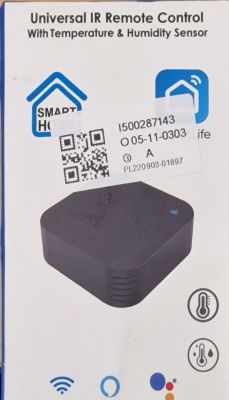
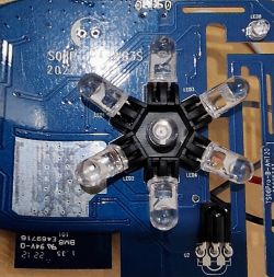
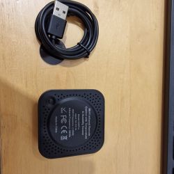
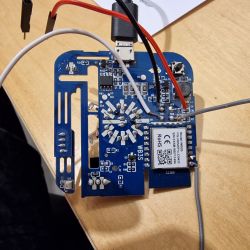
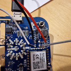
  • Teardown IR Blaster S06Pro WB3S Teardown IR Blaster S06Pro WB3S Teardown IR Blaster S06Pro WB3S

    Teardown IR Blaster S06Pro WB3S


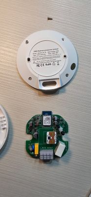
    Sold on Ebay quite often falsely marked as Zigbee (there is also a real Zigbee version)

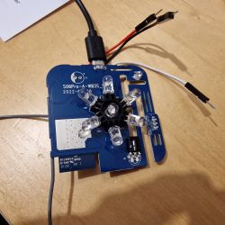
    Teardown IR Blaster S06Pro WB3S Teardown IR Blaster S06Pro WB3S

    Solder points easily visible an usable. Replacing software took a few attempts with shorting the top left contact to GND.

    Now the alternative software is running but I seem to be missing the IR resources...

    Cool? Ranking DIY
    About Author
    Homeuser2003
    Level 2  
    Offline 
    Homeuser2003 wrote 3 posts with rating 4. Been with us since 2022 year.
  • ADVERTISEMENT
  • #2 20238985
    p.kaczmarek2
    Moderator Smart Home
    Thanks for the teardown. IR features are required for this device, I know. @btsimonh has it covered. wait a few days and just do an OTA update, I will post further instructions here or in readme later.
    Do you know which pins are used for IR, etc?
    Helpful post? Buy me a coffee.
  • ADVERTISEMENT
  • #3 20239134
    Homeuser2003
    Level 2  
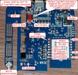
    Not sure which pins are used - but I found this elsewhere:

    Teardown IR Blaster S06Pro WB3S

    OTA sounds good but I still need to download a bin, right?

    THANKS!
  • #4 20239696
    p.kaczmarek2
    Moderator Smart Home
    Wow, that's a very nice breakdown of the module. Definitely it will come handy soon.

    OTA? For OBK OTA, you download correct file from Github and drag and drop it on OTA panel on our secondary Javascript panel.
    Helpful post? Buy me a coffee.
  • ADVERTISEMENT
  • #5 20244745
    Homeuser2003
    Level 2  
    Teardown IR Blaster S06Pro WB3S

    So the IR Signals have arrived. Already updated, thanks. But how do I translate the above into Pin numbers please? The Config Panel says "BK7231N/BK7231T supports PWM only on pins 6, 7, 8, 9, 24 and 26!", thus I must be missing something with a device in hand that has just 22 pins...

    Thanks

    Homeuser

    Added after 1 [hours] 46 [minutes]:

    Meanwhile configured ALL 28 Pins as IRRecv Channel 1. Should I not see a reaction in "log" when pointing an IR-Remote on it and pressing a button?

    Tried Channel 2 also...

    Thanks
  • #6 20244915
    p.kaczmarek2
    Moderator Smart Home
    Please update firmware to latest version. This is very experimental.

    Homeuser2003 wrote:

    Meanwhile configured ALL 28 Pins as IRRecv Channel 1. Should I not see a reaction in "log" when pointing an IR-Remote on it and pressing a button?

    This won't work because IR module takes FIRST pin with IRRecv role and others are ignored. You must know which pin has Receiver connected.

    Please see following table:
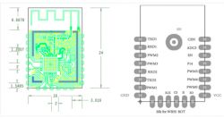
    Teardown IR Blaster S06Pro WB3S
    Pin No.SymbolI/O typeFunction
    1CENILow-level reset, high-level active (internally pulled high) Docking IC-CEN
    2ADC3AIADC pin, which is connected to the P23 pin on the internal IC
    3ENInputEnabling pin, which is internally pulled up and compatible with other module design
    4P14I/OCommon GPIO, which is connected to the P14 pin on the internal IC
    5PWM5I/OGPIOP_26, which is connected to the P26 pin on the internal IC
    6PWM4I/OGPIOP_24, common GPIO, which is connected to the P24 pin on the internal IC
    7PWM0I/OGPIOP_6, which is connected to the P6 pin on the internal IC
    8VCCPPower supply pin (3.3 V)
    9GNDPPower supply reference ground pin
    10PWM1I/OGPIOP_7, which is connected to the P7 pin on the internal IC
    11TXD2I/OUART2_TXD, which is used to display the internal information of the module and connected to the P0 on the internal IC. Unavailable to customers.
    12RXD2I/OUART2_RXD, which is used to display the internal information of the module and connected to the P1 on the internal IC. Unavailable to customers.
    13PWM3I/OGPIOP_9, common GPIO, which is connected to the P9 pin on the internal IC
    14PWM2I/OGPIOP_8, which is connected to the P8 pin on the internal IC
    15RXD1I/OUART1_RXD, which is used as a user-side serial interface pin and is connected to the P10 pin on the internal IC
    16TXD1I/OUART1_TXD, which is used as a user-side serial interface pin and is connected to the P11 pin on the internal IC


    According to your graphics, PWM2 is it receiver. Set the role only for this pin (ONLY THIS PIN) and then do Reboot module so IR driver can start. Then check again if you receive anything.

    Here is how it looks for me:
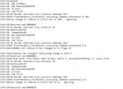
    Teardown IR Blaster S06Pro WB3S
    Helpful post? Buy me a coffee.
  • #7 20572975
    PrOmega
    Level 1  
    Maybe helpful for someone in the future :) :

    
    {
      "vendor": "Smart Life",
      "bDetailed": "0",
      "name": "IR Blaster S06Pro WB3S ",
      "model": "S06",
      "chip": "BK7231T",
      "board": "WB3S",
      "pins": {
        "6": "Btn;0",
        "8": "IRRecv;0",
        "9": "LED;0",
        "26": "IRSend;0"
      },
      "keywords": [
        "IR",
        "38kHz",
        "Remote",
        "USB"
      ],
      "image": "https://obrazki.elektroda.pl/3457161900_1665933908_thumb.jpg",
      "wiki": "https://www.elektroda.com/rtvforum/viewtopic.php?p=20238985#20238985",
      "product": "https://obrazki.elektroda.pl/4773578600_1665933910.jpg"
    }
    
  • #9 20761882
    ChewbaccaBG
    Level 1  
    Hey guys, how to I get the AHT20 sensor to work after flashing ? On my version of S06Pro it's AHT20
    IR recv works, haven't tested send yet (plan to link to HA)..

    Also, any guide for integrating into HA for controlling an air conditioner?
  • ADVERTISEMENT
  • #10 21079025
    rauno123
    Level 1  
    For the AHT20 Temperature and Humidity i used example from similar Tuya devices:

    
    startDriver TuyaMCU
    setChannelType 1 temperature_div10
    linkTuyaMCUOutputToChannel 101 val 1
    // dpID 102 is % humidity
    setChannelType 2 Humidity
    linkTuyaMCUOutputToChannel 102 val 2
    
  • #11 21344074
    Qua8824
    Level 4  
    Hi, just got an S06Pro from AliExpress.
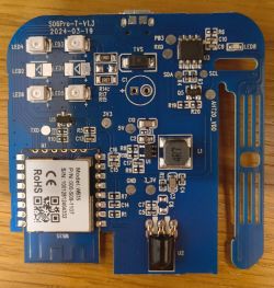
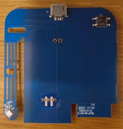
    Its full name is S06Pro-T-V1.3 dated on board to 2024-03-19 and looks like this:

    PCB of the S06Pro model, version S06Pro-T-V1.3 PCB board with blue laminate featuring micro USB port and soldering pads.

    It is different from the images posted on this post's head.

    Looking at this tutorial video: https://www.youtube.com/watch?v=KU0tDwtjfjw (from https://openbekeniot.github.io/webapp/devicesList.html ), they solder directly to the WB3S module, while on this post (and also on my board) there are dedicated (?) solder pads. Which should I use?
    Also, on the images above, the micro usb is also connected - does it need to be connected in parallel?

    Thanks!
  • #12 21344234
    divadiow
    Level 34  
    If it were mine I would solder all directly to the WB3S contacts and use the 5V USB for power - common ground with USB-TTL and S06.

    The TuyaMCU might get in the way, hampering your efforts, so you may have to sever either RX or TX between the WB3S and TuyaMCU. This could be a trace cut or an MCU leg lift.
  • #13 21344438
    p.kaczmarek2
    Moderator Smart Home
    This WB3S has only side rows of pads soldered, so it could even be easily removed from the board by using our tricky method shown here:


    but that's as a last resort, first just try flashing in-circuit...
    Helpful post? Buy me a coffee.
  • #14 21344944
    Qua8824
    Level 4  
    Thanks @divadiow

    divadiow wrote:
    If it were mine I would solder all directly to the WB3S contacts and use the 5V USB for power - common ground with USB-TTL and S06.


    I will do just that. So from the USB-TTL I will take only the GND, RX and TX.

    divadiow wrote:
    The TuyaMCU might get in the way, hampering your efforts, so you may have to sever either RX or TX between the WB3S and TuyaMCU. This could be a trace cut or an MCU leg lift.

    Not sure I fully understand what you wrote here, but let's see first if the first approach fails.

    Added after 50 [seconds]:

    >>21344438 Thanks. As you wrote - last resort... ;)
  • #15 21359092
    Qua8824
    Level 4  
    Me again, took me few days to get back to this one...
    So at the end I soldered to the pads as my soldering skills are so-so. Anyway, Using latest version of the BK7231 flasher (BK7231GUIFlashTool-v5), I done first a backup and then flashed. It ended up with a crc error. Looking at the site for the crc what to do section, I stupidly changed the chip type to BK7231N. Since that moment I cannot put the device in boot mode. It has a reset button on the bottom of the PCB that a long click on it worked on the intents described above. There was also a blue led blinking that now is not. Have I bricked the device? Any advice what to do to try to fix it?
    Thanks in advance!

    EDIT
    I shortcut the CEN leg with GND and it worked like a charm :) (using BK7231T of course...) not sure why the CRC error happened earlier.
  • #16 21362349
    Qua8824
    Level 4  
    Hi, to continue the journey - I now try to make the unit read the commands from the AC remote control, but I'm not sure what to do to make it work. I tried the following:

    1. copied the json mentioned above and imported it to the unit. to be specific I used this pinout:
    "pins": {
    "6": "Btn;0",
    "8": "IRRecv;0",
    "9": "LED;0",
    "26": "IRSend;0"
    },
    2. tested with pins 6 and 26 set to 1 instead of 0.
    3. tried with 2 different remote controls (2 different brands)

    The log shows many lines like this "Info:MAIN:Time 4046, idle 26329/s, free 82744, MQTT 1(44), bWifi 1, secondsWithNoPing -1, socks 2/38", periodically shows the wifi data and if I toggle Channel 0 from the home page, it shows also on the log.

    Any help will be appreciated!
  • #17 21362362
    divadiow
    Level 34  
    are you setting powersave 1? try powersave 0 then check the logs after pressing buttons on remote
  • #18 21362516
    Qua8824
    Level 4  
    Thanks @divadiow , setting PowerSave to 0 made the unit print log lines like the following, when clicking the power button on one of the remotes:
    Info:IR:IR IR_PulseDistance 0xD21 0xD0B 0 (35 bits)
    Info:IR:IR IR_PulseDistance 0xD21 0xD0B 0 (35 bits)
    Info:IR:IR IR_PulseDistance 0xD21 0xD0B 0 (31 bits)
    Info:IR:IR IR_PulseDistance 0xD21 0xD0B 0 (35 bits)
    Info:IR:IR IR_PulseDistance 0xC22 0xC0C 0 (31 bits)

    That's great.
    Only that the air condition I need to control is using the other remote control which did not create any response from the device. Anything possible to do in order to fix it?

Topic summary

The discussion revolves around the teardown and software modification of the IR Blaster S06Pro WB3S, which is often misrepresented as a Zigbee device on eBay. Users share insights on the IR functionality, firmware updates, and pin configurations necessary for proper operation. The author successfully replaced the software but encountered issues with missing IR resources. Participants provide guidance on identifying the correct pins for IR signals and suggest downloading firmware from GitHub for over-the-air (OTA) updates. Additionally, there are inquiries about integrating the device with Home Assistant (HA) and utilizing the AHT20 sensor for temperature and humidity readings.
Summary generated by the language model.
ADVERTISEMENT