

Teardown
I recently purchased this generic 6-zone 24V WiFi sprinkler controller on AliExpress:
→ https://www.aliexpress.com/item/1005008893463104.html

Hardware Description
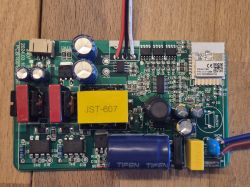
The device uses a CBU module (BK7231N) and contains two separate 74HC595 shift registers.

The board is quite well designed for flashing. It even has a pin header footprint that directly exposes +3.3V, RX, TX and GND. This is quite rare on Tuya device and made flashing very straightforward.

There are two 74HC595 shift registers on the board:
The right 74HC595 controls the Triacs that switch the 24V outputs to the valves.
The left 74HC595 is used only for the status LEDs on the front panel.
On the side of the device there are three physical buttons. In the original Tuya firmware these were used to manually cycle through zones (Up/Down) and manually open a zone (Enter). For my own use I simply mapped them to the first three valve channels.
Flashing
Because of the convenient pin header, flashing was very easy. I connected a USB-UART adapter and flashed OpenBeken without any need to cut traces or solder wires.
Configuration
Below is the final configuration that is currently running on the device:
During the configuration process I discovered that the existing ShiftRegister driver only supported a single 74HC595 instance. Because this board uses two independent shift registers (one for valves, one for LEDs), I had to modify the driver so it can handle multiple chips at the same time.
The modification involved changing the global variables into an array of structures (shiftReg_t) so that each command of startDriver ShiftRegister creates a new independent instance. After the change, both 74HC595 chips can be used simultaneously without one overwriting the configuration of the other.
Summary
This turned out to be a relatively easy device to convert to OpenBeken, mainly thanks to the built-in pin header. The only complication was the need to extend the ShiftRegister driver to support multiple chips. After the driver update and a bit of reverse engineering of the pin mapping, all six valves work correctly.
I recently purchased this generic 6-zone 24V WiFi sprinkler controller on AliExpress:
→ https://www.aliexpress.com/item/1005008893463104.html

Hardware Description
The device uses a CBU module (BK7231N) and contains two separate 74HC595 shift registers.

The board is quite well designed for flashing. It even has a pin header footprint that directly exposes +3.3V, RX, TX and GND. This is quite rare on Tuya device and made flashing very straightforward.

There are two 74HC595 shift registers on the board:
The right 74HC595 controls the Triacs that switch the 24V outputs to the valves.
The left 74HC595 is used only for the status LEDs on the front panel.
On the side of the device there are three physical buttons. In the original Tuya firmware these were used to manually cycle through zones (Up/Down) and manually open a zone (Enter). For my own use I simply mapped them to the first three valve channels.
Flashing
Because of the convenient pin header, flashing was very easy. I connected a USB-UART adapter and flashed OpenBeken without any need to cut traces or solder wires.
Configuration
Below is the final configuration that is currently running on the device:
{
  "vendor": "Tuya",
  "bDetailed": "0",
  "name": "6-Zone 24V Sprinkler Controller (CBU + 2x 74HC595)",
  "model": "Sprinkler-6Z-24V",
  "chip": "BK7231N",
  "board": "CBU",
  "flags": "1024",
  "keywords": [
    "Sprinkler",
    "Irrigation",
    "74HC595",
    "Valve"
  ],
  "pins": {
    "6": "Btn;2;2",
    "7": "Btn;3;3",
    "8": "Btn;1;1"
  },
  "command": "backlog startDriver ShiftRegister 16 20 22 1 1 1; startDriver ShiftRegister 9 17 15 1 1 1; setChannelType 1 Toggle_Inv; setChannelType 2 Toggle_Inv; setChannelType 3 Toggle_Inv; setChannelType 4 Toggle_Inv; setChannelType 5 Toggle_Inv; setChannelType 6 Toggle_Inv",
  "image": "https://obrazki.elektroda.pl/...",
  "wiki": "https://www.elektroda.com/rtvforum/topic_xxxx.html"
}
During the configuration process I discovered that the existing ShiftRegister driver only supported a single 74HC595 instance. Because this board uses two independent shift registers (one for valves, one for LEDs), I had to modify the driver so it can handle multiple chips at the same time.
The modification involved changing the global variables into an array of structures (shiftReg_t) so that each command of startDriver ShiftRegister creates a new independent instance. After the change, both 74HC595 chips can be used simultaneously without one overwriting the configuration of the other.
Summary
This turned out to be a relatively easy device to convert to OpenBeken, mainly thanks to the built-in pin header. The only complication was the need to extend the ShiftRegister driver to support multiple chips. After the driver update and a bit of reverse engineering of the pin mapping, all six valves work correctly.