logo elektroda
logo elektroda
X
logo elektroda

[BK7231N/CBU] Tuya TH01? Generic Wi-Fi Temperature & Humidity Sensor [CHT8310]

divadiow 22350 128
ADVERTISEMENT
  • #1 20851544
    divadiow
    Level 34  
    I see some variations of this around on the forums, but I don't think I see this one with a Sensylink CHT8310 humidity and temperature sensor.

    I'm new to flashing these devices so I've been on a bit of a buying spree, wanting to play with all the IoT variations. AliExpress has fuelled quite a bit of this! This unit is labelled as a TH08 on the buyer's product page as well as the sticker slapped on the tiny box the device comes in. This was the exact store/unit: https://www.aliexpress.com/item/1005005869874007.html
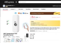
    AliExpress product page featuring a WiFi temperature and humidity sensor.

    I thought TH08s were the square temp/hum units with the LCD screen and these were TH01s, but it seems to vary?

    It was bought in a 3 choice items/free shipping bundle, so all these cost £6-£7 shipped. Ordered 27th October, arrived 7th December. UK
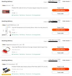
    AliExpress order list with electronic devices, including a humidity and temperature sensor.

    CHT8310 datasheet
    CBU datasheet

    To get the boot logs I used RX2, TX2 and GND and to capture all the logs from very first power-on, I used 2x AAA batteries in the unit itself (carefully inching one back in to power on). I'm not sure how others are capturing the whole log for non-battery devices without disconnecting the USB-TTL adaptor and upsetting the com port.
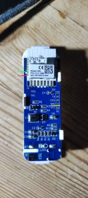
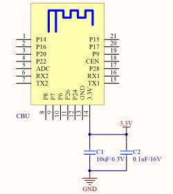
    Temperature and humidity sensor module with visible labels and pins.
    Diagram of an integrated circuit with pin labels and capacitors.

    I had great difficulty getting BKFlasher to complete for some reason, so I swapped a few jumper cables out and settled on using VCC direct on the CBU board pin.

    The USB-TTL adaptor I used is CH340 Winchiphead based device from Amazon, https://www.amazon.co.uk/dp/B0B7RHPMT7

    And now for some pics of the unit, inside and out.
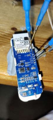
    Interior view of a temperature and humidity sensor with connected wires.

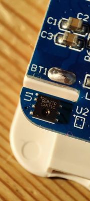
    Close-up of a circuit board with a chip marked S8310 and other electronic components.

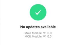
    Yes, I paired it with the Tuya app to check on firmware versions. I guess at 1.0.0 cloudcutter should be an option. I have not tried cloucutter. I might order another one, hope I get the same, then try cloudcutter.

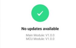
    Screen of a temperature and humidity sensor app with data.
    App screen indicating no updates available.

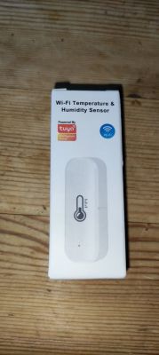
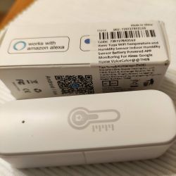
    Box of a white Wi-Fi temperature and humidity sensor with Powered by Tuya logo and Wi-Fi icon.

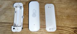
    Disassembled white plastic temperature and humidity sensor with visible interior on a wooden surface.

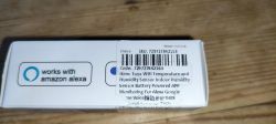
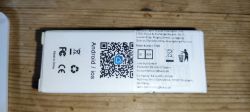
    Packaging of Tuya WiFi temperature and humidity sensor with Amazon Alexa compatibility label.

    View of device packaging with manufacturer information and QR code.

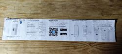
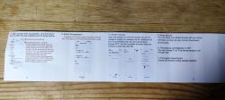
    User manual with technical data for Wi-Fi temperature and humidity sensor.
    Temperature and humidity sensor user manual.

    After using Putty to get the output logs I used BK Easyflasher 1.1.3 to dump the firmware, attached.

    BKEF didn't seem to be able to find any meaningful pin data, however.

    Update: No change in BK GUI Flasher in v1.1.4
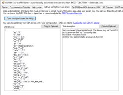
    Screenshot of BK7231 Easy UART Flasher software with JSON results.

    Before I proceed to flashing OpenBeken, is there anything else I should dump/do?

    Update 19/02/2024: WIP OBK Template
    Update 21/02/2024: Complete template
    Code: JSON
    Log in, to see the code
  • ADVERTISEMENT
  • #2 20851756
    p.kaczmarek2
    Moderator Smart Home
    The CHT8310 datasheet link requires a login. Do you have an already downloaded pdf version of that datasheet?
    Helpful post? Buy me a coffee.
  • #4 20851834
    p.kaczmarek2
    Moderator Smart Home
    Your datasheet is incomplete. It has no protocol details. Luckily it has turned out that I saw someone mentoning it on Github already, so I have a full datasheet. See attachment:
    CHT8310.Ad...230407.pdf Download (3.98 MB)
    I may try to add support for this chip, would you help with testing?
    Helpful post? Buy me a coffee.
  • #5 20851836
    divadiow
    Level 34  

    Ah, OK, sure. I'm not sure I have the ability/understanding (yet) of what to do next with the datasheets. I'll review that GitHub to see if I can work it out.

    Added after 3 [minutes]:

    >>20851834

    Sorry, yes. I will help with testing, of course!
  • #6 20852460
    kuncy7
    Level 9  
    I have exactly the same sensor:
    Tuya temperature and humidity sensor with packaging.

    I tried using cloudcutter, but this is what I end up with:
    
    Scanning for open Tuya SmartLife AP
    .............................................
    Found access point name: "SmartLife-13F8", trying to connect...
    Device 'wlan0' successfully activated with '744f9eab-37e5-4ba0-8952-dd828cd704d7'.
    Connected to access point.
    Waiting 1 sec to allow device to set itself up...
    Running initial exploit toolchain...
    Exploit run, saved device config too!
    output=/work/configured-devices/PuHhevM5TMz0.deviceconfig
    Saved device config in /work/configured-devices/PuHhevM5TMz0.deviceconfig
    
    ================================================================================
    Power cycle and place your device in AP (slow blink) mode again.  This can usually be accomplished by either:
    Power cycling off/on - 3 times and wait for the device to fast-blink, then repeat 3 more times.  Some devices need 4 or 5 times on each side of the pause
    Long press the power/reset button on the device until it starts fast-blinking, then releasing, and then holding the power/reset button again until the device starts slow-blinking.
    See https://support.tuya.com/en/help/_detail/K9hut3w10nby8 for more information.
    ================================================================================
    
    Scanning for open Tuya SmartLife AP
    ..............
    Found access point name: "SmartLife-13F8", trying to connect...
    Device 'wlan0' successfully activated with '744f9eab-37e5-4ba0-8952-dd828cd704d7'.
    Connected to access point.
    ================================================================================
    [!] The profile you selected did not result in a successful exploit.
    ================================================================================


    Is there a chance for a profile for this sensor?
  • #7 20852625
    divadiow
    Level 34  
    I think that means it's running a patched firmware. I've got two mini 16a aubess switches that did that today with firmware 1.3.10, which is on the known patches firmware list. What firmware is your device?
  • #9 20866909
    kikokbg
    Level 3  

    Hi all, is there any update regarding flashing OpenBK firmware to this device? I have exactly the same sensor, so I can help with testing if needed.
  • ADVERTISEMENT
  • #12 20867436
    Baustromverteiler
    Level 3  

    I used the GUI Flasher: https://github.com/openshwprojects/BK7231GUIFlashTool

    Chip Type is BK7231N, selected "Download latest Firmware from Web"

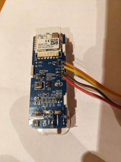
    connected the VCC, GND, TX, RX to a USB to Serial adapter (TX on the Sensor to RX on the USB-serial Interface, RX on the Sensor to TX on the serial interface)

    Circuit board with connected VCC, GND, TX, and RX wires.

    Then I clicked on "Do Firmware write" and shortly disconnected / reconnected the positive lead to the serial interface and it flashed just fine. If you have trouble flashing despite everything seems fine try another serial interface, I first tried it with a CH340 interface and the flash wouldn't start, tried another interface and it worked just fine with the same settings.
  • ADVERTISEMENT
  • #13 20868622
    kikokbg
    Level 3  
    Thank you for your detailed explanation! 👍
  • Helpful post
    #14 20874759
    p.kaczmarek2
    Moderator Smart Home
    Thanks to the hard work of our contributor, we have now a CHT8310 support in CHT8305 driver.

    You just need to enable CHT8305 driver, it should handle new kind of sensor as well.

    Please update and try.

    Also, when enabling, watch out for message in log:
    
    Info:SENSOR:DRV_CHT8305_init: ID: 59 59 8215
    

    Let me know what kind of ID do you have there.
    Helpful post? Buy me a coffee.
  • #15 20874819
    divadiow
    Level 34  

    Yes. Excellent stuff. I will try again and report when I'm home on the 27th.
  • #16 20876020
    Baustromverteiler
    Level 3  

    Now that's great news, thanks a lot to artin961 :)

    Here's the Log with the Sensor-ID:

    Info: SENSOR: DRV_CHT8305_init: ID: 59 59 8215
  • #17 20876024
    p.kaczmarek2
    Moderator Smart Home
    So, @Baustromverteiler , is the sensor working for you?
    Helpful post? Buy me a coffee.
  • #18 20876035
    Baustromverteiler
    Level 3  

    Works just fine, need to calibrate it, temp is probably a degree too high

    App screen showing temperature and humidity information with configuration options.
  • ADVERTISEMENT
  • #19 20876365
    artin961
    Level 2  

    Hello all,
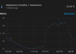
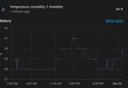
    Just as a follow-up, this is the autoexec.bat I used to make it sleep and not drain the battery as fast. A delay of 50 seconds is enough to connect and send data to MQTT as well as to be able to debug after restarting it. 900 seconds can be increased to preserve the battery even more. It would be great if a timer sleep with button wakeup gets implemented in the future to be able to wake it manually from the button. As can be observed in the screenshots below, it wakes and sends data to HA just fine.

    
    PowerSave 1
    delay_ms 50000
    DeepSleep 900


    Temperature sensor graph showing changes from 2:00 AM to 11:00 PM on December 26th. Chart showing temperature and humidity with a current humidity value of 40%.

    Hope you find this post useful.
    Regards.
  • #20 20876516
    p.kaczmarek2
    Moderator Smart Home
    @artin961 I would suggest to change this autoexec to respect variation in the MQTT connection time. Please consider something like this:
    
    startDriver NTP
    startDriver SSDP
    
    // now wait for MQTT
    waitFor MQTTState 1
    // extra delay, to be sure
    delay_s 1
    publish myVariable 2022
    // you can publish again just to be sure
    // delay_s 1
    // publish myVariable 2022
    
    // if you have a battery powered device, you can now uncomment this line:
    // Deep sleep (shut down everything) and reboot automatically after 600 seconds
    //DeepSleep 600
    

    Please see our autoexec.bat examples here:
    https://github.com/openshwprojects/OpenBK7231T_App/blob/main/docs/autoexecExamples.md
    Search for "waitFor" to see more samples.
    Helpful post? Buy me a coffee.
  • #21 20878834
    divadiow
    Level 34  
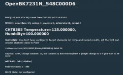
    Curious, mine has 8304 in the log, not 8305.

    Info:SENSOR:DRV_CHT8304_readEnv: Temperature:125.000000C Humidity:100.000000%


    Info:SENSOR:DRV_CHT8305_init: ID: FF FF FFFF
    Error:CMD:command with name CHT_Calibrate already exists!
    Error:CMD:command with name CHT_Cycle already exists!
    Info:MAIN:Started cht8305.


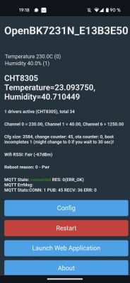
    Screenshot of OpenBK software with temperature and humidity sensor readings.

    My startup command is

    backlog PowerSave 1; startDriver SSDP; startDriver Wemo; startDriver NTP; startDriver CHT8305


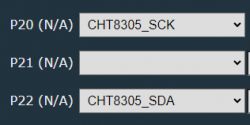
    What flags have you set @Baustromverteiler and what channel/pin settings?

    Added after 12 [minutes]:

    Silly me https://github.com/openshwprojects/OpenBK7231T_App/issues/983#issue-1997790886

    Screenshot showing interface elements with labels P20, P21, P22 and associated values CHT8305_SCK and CHT8305_SDA.

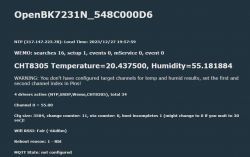
    Info:SENSOR:DRV_CHT8305_init: ID: 59 59 8215


    Screenshot of the OpenBK7231N interface displaying CHT8305 data and a channel configuration warning.

    Added after 9 [hours] 48 [minutes]:

    OBK template for this variant

    Code: JSON
    Log in, to see the code
  • #22 20892163
    kikokbg
    Level 3  

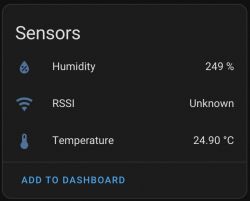
    I have successfully flashed the OpenBK firmware, but I'm observing a strange behavior in the integration with Home Assistant via MQTT. In Home assistant the values of the [b]Temperature[/b] and the [b]Humidity[/b] keeps changing every second.

    Here is one example:

    Screenshot of the sensor panel showing humidity at 249% and temperature at 24.90°C.

    I think that here the [b]Humidity[/b] show the correct value of the humidity in the room while the [b]Temperature[/b] show the value of the humidity in the room / 10.

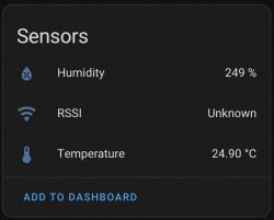
    after a second those values are changed to the following:

    Sensor panel with humidity at 249%, RSSI unknown, and temperature at 24.90°C.

    I think that here the [b]Temperature[/b] is showing the correct value of the temperature in the room while the [b]Humidity[/b] is showing the value of the temperature in the room * 10.

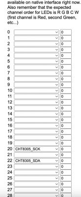
    Here are my PIN settings:

    Screenshot of PIN settings in a configuration interface.

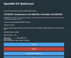
    The index page shows the correct values for [b]Temperature[/b] and [b]Humidity[/b] and there they are not changing like in HA.

    OpenBK app screen with incorrect temperature and humidity values.

    Any suggestions where the problem might be?

    And additionally - what should I do to solve the warning message, which is visible on the index page?
  • #23 20892220
    p.kaczmarek2
    Moderator Smart Home
    This warning tells you what's wrong.

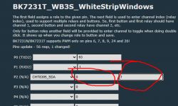
    You need to configure second channel for SDA/DAT pin to be other channel than first:
    Pin configuration settings for BK7231T_WB3S with selected channel for P2.
    That's done in Configure Module...
    Helpful post? Buy me a coffee.
  • #24 20892560
    kikokbg
    Level 3  

    p.kaczmarek2 wrote:
    This warning tells you what's wrong.

    You need to configure the second channel for SDA/DAT pin to be a different channel than the first:
    Pin configuration settings for BK7231T_WB3S with selected channel for P2.
    That's done in Configure Module...


    Thank you very much! The correct configuration has solved the issue.
  • #25 20914974
    hojnikb
    Level 11  

    Did anyone figure out which pins are used to measure battery level?
  • #26 20915041
    p.kaczmarek2
    Moderator Smart Home
    Well, we need to figure BAT_Relay pin, because ADC is always on P23 so that we can already know without checking.

    PS: Search for "BAT_ADC" here:
    https://github.com/OpenBekenIOT/webapp/blob/gh-pages/devices.json
    Maybe one of the templates can match?
    Helpful post? Buy me a coffee.
  • #27 20915250
    hojnikb
    Level 11  

    p.kaczmarek2 wrote:
    Well, we need to figure out the BAT_Relay pin because the ADC is always on P23, so we can already know without checking.

    PS: Search for "BAT_ADC" here:
    https://github.com/OpenBekenIOT/webapp/blob/gh-pages/devices.json
    Maybe one of the templates can match?


    Thank you!
    Guess it's a trial and error game then to find the correct one :D
    Is the channel selection on each the bat_adc and bat_relay pin also important?
  • #28 20915508
    p.kaczmarek2
    Moderator Smart Home
    Just choose an unused one so it does not interfere with anything
    Helpful post? Buy me a coffee.
  • #29 20916329
    artin961
    Level 2  

    Hello,

    For me, I think the BAT_Relay was P8. But on different modules, it may be elsewhere. I used a multimeter to measure without the device being powered. Best to look for a group of 4 resistors and a MOSFET. The MOSFET has its gate pulled down to ground with the first resistor (10k typically). There should be another resistor from the gate to the pin, you need a smaller value like 1k or 4.7k. The last 2 resistors should be connected in series, their values should be the same. The midpoint goes to ADC pin 23, one side to the drain of the MOSFET and the other to 3v.

    The idea is to lower the voltage being measured to be in the range of the ADC and below the main power rail. This is accomplished using a voltage divider, making it half of the battery voltage. If you connect the divider permanently to the battery, it will take a small amount of current all the time, so the MOSFET is used to connect the divider just to take a measurement.

    On some devices, there is also a switching power supply, a boost converter that makes 3.3v from the batteries. If I remember correctly, on my sensor, it was always enabled, but on a door sensor, I saw it connected to a pin so the MCU can "boost its voltage". I'm not sure how to properly handle that. I made it always high pin for now, hope it doesn't drain the battery much.
  • #30 20917860
    hojnikb
    Level 11  

    Does anyone else experience very poor precision on lower temps? I've noticed that when temps drop below 10°C, its accuracy drops off even further. While at ~20-25°C, it's usually around 2°C off (easily fixed by offsetting), by 10 or even 0°C, it's easily off by ~5°C or more (shows higher than it actually is).

    Any way to calibrate or something? Or is CHT8310 just that inaccurate.

Topic summary

The discussion revolves around the Tuya TH01 and its variations, particularly focusing on the CHT8310 temperature and humidity sensor. Users share experiences with flashing the device using OpenBK firmware, troubleshooting issues related to incorrect temperature and humidity readings, and configuring the device for optimal battery performance. Key topics include the use of the ALERT pin for power-saving features, calibration of sensor readings, and the integration of the device with Home Assistant via MQTT. Users also discuss the challenges of using the device with low battery levels and the need for proper pin configuration to avoid boot loops. The conversation highlights the importance of firmware updates and community support in enhancing device functionality.
Summary generated by the language model.
ADVERTISEMENT