logo elektroda
logo elektroda
X
logo elektroda

Gosund Nite Bird WB4 - Issues Flashing Tasmota Firmware, No Feedback

domio33 1470 29
ADVERTISEMENT
Treść została przetłumaczona polish » english Zobacz oryginalną wersję tematu
  • #1 20367145
    domio33
    Level 28  
    Hi all,
    I have a problem with changing the software on the tasmote in the gosund bulb wb4.

    Despite soldering in the leads I still have no feedback communication from the controller.

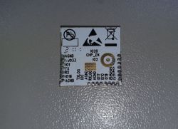
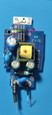
    Below I insert pictures I found on a German forum :
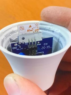

    Gosund Nite Bird WB4 - Issues Flashing Tasmota Firmware, No Feedback

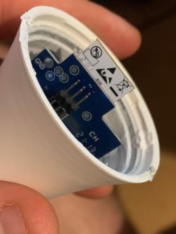
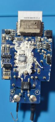
    And here my bulb


    Gosund Nite Bird WB4 - Issues Flashing Tasmota Firmware, No Feedback

    As you can see, mine is newer (?) , does not have the signed pins , although the board looks identical.

    Question whether the controller may have been changed and therefore does not detect my computer, or have been routed differently pins ?

    Anybody here has changed the software in this bulb ?
    I would appreciate an answer :) .
  • ADVERTISEMENT
  • #2 20371810
    p.kaczmarek2
    Moderator Smart Home
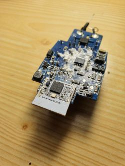
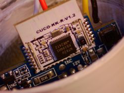
    What WiFi module is in there? More pictures please, you have not shown the WiFi module on the front and I can't see its designation.
    Helpful post? Buy me a coffee.
  • #3 20514563
    maxikaaz86
    Level 12  
    @domio33
    @p.kaczmarek2
    I will dig up the topic because I just happen to have a few of these bulbs and at some point the manufacturer changed the ESP to W701H(?). Also, I could not find a module that looks the same or similar on the Tuya website.
    Gosund Nite Bird WB4 - Issues Flashing Tasmota Firmware, No Feedback .
  • ADVERTISEMENT
  • #4 21379255
    p.kaczmarek2
    Moderator Smart Home
    Helpful post? Buy me a coffee.
  • #6 21438564
    divadiow
    Level 36  
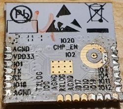
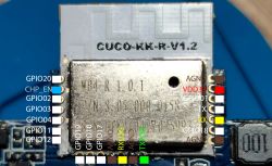
    @maxikaaz86 has de-soldered the CUCO-KK-R-V1.2 module and kindly provided us with a pic of the rear, which I now post

    Image of the desoldered CUCO-KK-R-V1.2 module with visible pin markings.
    The image shows the backside of the CUCO-KK-R-V1.2 electronic module with visible pin labels and connection instructions.

    This W701H module requires 2 IOs to be pulled to 3.3v

    Code: Text
    Log in, to see the code


    RX is GPIO13
  • #7 21699333
    LeMaxime
    Level 7  
    Spoiler:

    03.10.2025 - All in this spoiler is OUTDATED,saved for history
    I flashed it using the method above, but there's a problem. The RGB LEDs are fully controllable, both color and brightness. But the white LEDs can only be turned on and off, without brightness control. They turn on immediately at maximum brightness. The RGB LEDs are controlled by PWM, so if I set the GPIO that turns the white LEDs on and off to PWM, the bulb resets instantly. So I guess I need to look for a dimmer on a different pin?

    My config(WIP)
    
    {
      "vendor": "Gosund",
      "bDetailed": "0",
      "name": "Nitebird Gosund Smart Bulb Color WB4",
      "model": "WB4",
      "chip": "RTL87X0C",
      "board": "TODO",
      "flags": "17040384",
      "keywords": [
        "TODO",
        "TODO",
        "TODO"
      ],
      "pins": {
        "3": "PWM;3",
        "4": "PWM;1",
        "11": "PWM;2",
        "17": "PWM;4"
      },
      "command": "",
      "image": "https://obrazki.elektroda.pl/YOUR_IMAGE.jpg",
      "wiki": "https://www.elektroda.com/rtvforum/topic_YOUR_TOPIC.html"
    }


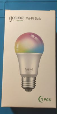
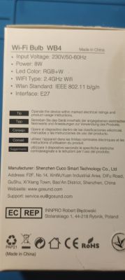
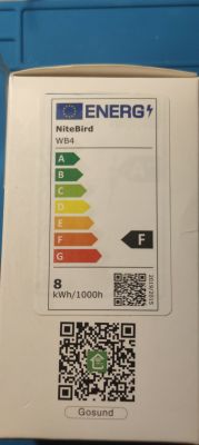
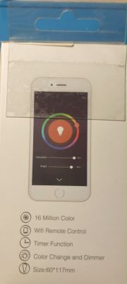
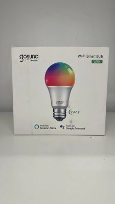
    Box photo:
    Gosund Nite Bird WB4 - Issues Flashing Tasmota Firmware, No Feedback
    Gosund Nite Bird WB4 - Issues Flashing Tasmota Firmware, No Feedback
    Gosund Nite Bird WB4 - Issues Flashing Tasmota Firmware, No Feedback
    Gosund Nite Bird WB4 - Issues Flashing Tasmota Firmware, No Feedback

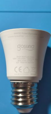
    Bulb case photo:
    Gosund Nite Bird WB4 - Issues Flashing Tasmota Firmware, No Feedback

    Bulb board photo:
    Gosund Nite Bird WB4 - Issues Flashing Tasmota Firmware, No Feedback
    Gosund Nite Bird WB4 - Issues Flashing Tasmota Firmware, No Feedback

    Cuko-KK-R-V1.2 Pinout(W701 module):
    Gosund Nite Bird WB4 - Issues Flashing Tasmota Firmware, No Feedback

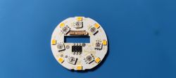
    LEDs board:
    Gosund Nite Bird WB4 - Issues Flashing Tasmota Firmware, No Feedback


    Preparing to flashing OpenBK:
    (PIN on board -> UART)
    VDD33 -> +3.3V
    AGND -> GND
    TXLOG -> RX
    RXLOG -> TX
    
    RX -> +3.3V(or VDD33 on module) (to enter flashing mode, must be connected all the time)
    IO0 -> +3.3V(or VDD33 on module) (to enter flashing mode, must be connected all the time)
    
    CEN -> AGND or module metal shell (only momentarily to reset the chip)


    Use OpenBK binaries for UART RTL87X0C (for example OpenRTL87X0C_1.18.187.bin)

    Backup stock firmware:
    Use https://github.com/libretiny-eu/ltchiptool:
    Settings: 115200 baud rate,Chip family - Realtek AmebaZ2
    Then use "Read flash" and "Read ROM"


    How to flash:
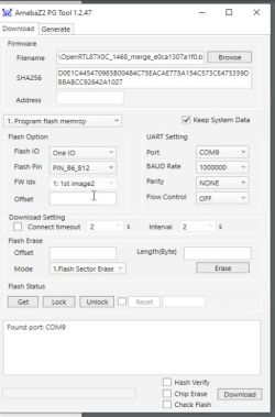
    Use AmebaZ2 PG Tool(u can download one in attached files) and set settings like this:
    Gosund Nite Bird WB4 - Issues Flashing Tasmota Firmware, No Feedback


    Config:
    {
      "vendor": "Gosund",
      "bDetailed": "0",
      "name": "Nitebird Gosund RGB+W Smart LED Bulb",
      "model": "WB4",
      "chip": "RTL87X0C",
      "board": "CUCO-KK-R-V1.2",
      "flags": "17040384",
      "keywords": [
        "tuya",
        "lamp"
      ],
      "pins": {
        "3": "PWM;3",
        "4": "PWM;1",
        "11": "PWM;2",
        "17": "PWM;4"
      },
      "command": "powersave 1",
      "image": "https://obrazki.elektroda.pl/8358343600_1759248710.png",
      "wiki": "https://www.elektroda.com/rtvforum/topic3946504.html"
    }


    Tip:
    If you plan to add that bulb in Home Assistant and want correct working Cool White LEDs - remove Flag 24 AFTER Home Assistant Discovery
  • ADVERTISEMENT
  • #8 21699629
    divadiow
    Level 36  
    Code: Text
    Log in, to see the code


    this is the IO that is white LED?
  • #9 21699636
    p.kaczmarek2
    Moderator Smart Home
    So this is RGBW device, not RGBCW? It's a shame there is not more information in the first post.

    The bulb may reset if it was designed to run in either RGB or CW, and you try to run it with both RGB and CW at the same time. It overloads. Or maybe it needs powersave...
    Helpful post? Buy me a coffee.
  • #10 21699770
    LeMaxime
    Level 7  
    >>21699629
    yes
    >>21699636
    yes.bulb box says that bulb is "RGB+W"
    "The bulb may reset if it was designed to run in either RGB or CW, and you try to run it with both RGB and CW at the same time. It overloads. Or maybe it needs powersave..."
    RGB led was off when im trying to change type from 'Rel' to 'PWM'
    PowerSave 1 doesnt help
  • #12 21700845
    LeMaxime
    Level 7  
    >>21700820 well maybe white led using another pin for brightness control?
    I'll pick up two more of these bulbs today, if I could get a dump and look at the configuration with Tuya...
  • #13 21701811
    divadiow
    Level 36  
    yes, a dump would be interesting I suppose. Was white definitely brightness-controllable with factory firmware? I assume so.
  • #14 21704263
    LeMaxime
    Level 7  
    divadiow wrote:
    Was white definitely brightness-controllable with factory firmware?

    Yes,i checked this
    so now im searching for original firmware backup tool
  • ADVERTISEMENT
  • #16 21704330
    LeMaxime
    Level 7  
    >>21704315 yes,i run it
    "58384/2097152 bytes | 2.25 KB/s | ETA 14:56"
    sooooooooooo long xddd
    ive used 115200 baud so wait a little bit
  • #18 21704347
    LeMaxime
    Level 7  
    >>21704335
    well looks like itchiptool can read flash too so i can finally upload a stock Tuya firmware,thats backup contains my Wi-Fi Las_Vegas and password for it, and also attached to my Tuya account(dont worry,its test account,only that bulb attached to him)
    ive attached a few files:
    WB4Full_flash.bin - full flash backup from itchiptool
    WB4Rom.bin - ROM backup from itchiptool
    WB4_Script.bin - full flash(?) backup from ur script

    also i checked md5 hashes - itchiptool and ur script has the same md5 hashes
  • #19 21704350
    divadiow
    Level 36  
    OK. downloaded. will test shortly :)

    Added after 21 [minutes]:

    I am pleased to report both full backups are identical. I was able to flash, it boots and pairs with Tuya. Here is boot log

    Code: Text
    Log in, to see the code


    no automatic pin extraction though
  • #20 21704379
    LeMaxime
    Level 7  
    >>21704350 Damn, I was hoping the dump would help, but alas. Any ideas how control white leds xd?
  • #21 21704382
    divadiow
    Level 36  
    could allow PWM on PA10 I guess to see what it does. It would need a custom build
  • #22 21704401
    LeMaxime
    Level 7  
    >>21704382 well, building is too hard for me so cant help with that(
  • #23 21704403
    divadiow
    Level 36  
    just a thought, please try setting PA17 as white PWM
  • #24 21704430
    insmod
    Level 28  
    Tuya RTL sdk doesn't allow PA10 as PWM. It was a moot point though, since it's a hardware limitation.
    const static pwm_dev_t tkl_pwm_switch[PWM_DEV_NUM][4] = {
        [0] = {
            {.pin = PA_0, .obj = NULL},
            {.pin = PA_11, .obj = NULL},
            {.pin = PA_20, .obj = NULL},
            {.pin = NC, .obj = NULL},
        },
        [1] = {
            {.pin = PA_1, .obj = NULL},
            {.pin = PA_12, .obj = NULL},
            {.pin = NC, .obj = NULL},
        },
        [2] = {
            {.pin = PA_2, .obj = NULL},
            {.pin = PA_14, .obj = NULL},
            {.pin = NC, .obj = NULL},
        },
        [3] = {
            {.pin = PA_3, .obj = NULL},
            {.pin = PA_15, .obj = NULL},
            {.pin = NC, .obj = NULL},
        },
        [4] = {
            {.pin = PA_4, .obj = NULL},
            {.pin = PA_16, .obj = NULL},
            {.pin = NC, .obj = NULL},
        },
        [5] = {
            {.pin = PA_17, .obj = NULL},
            {.pin = NC, .obj = NULL},
        },
        [6] = {
            {.pin = PA_18, .obj = NULL},
            {.pin = NC, .obj = NULL},
        },
        [7] = {
            {.pin = PA_13, .obj = NULL},
            {.pin = PA_19, .obj = NULL},
            {.pin = PA_23, .obj = NULL},
            {.pin = NC, .obj = NULL},
        }
    };
    
  • #25 21704431
    divadiow
    Level 36  
    also, there's this flag to play with (if PA17 is right)

    Code: Text
    Log in, to see the code
  • #26 21704580
    LeMaxime
    Level 7  
    >>21704403
    well,so strange
    i flashed second bulb and set PA17 as white PWM on 4 channel - its worked, white LEDs fully controllable(turn on/off and brightness)
    and PA10 al relay not working
    but with first buld that magic not worked
    IO17 pin in CUCO-KK-R-V.1.2 module is PA17 in OpenBK,correct?
  • #27 21704896
    divadiow
    Level 36  
    ah good.

    this was in boot log

    Code: Text
    Log in, to see the code


    LeMaxime wrote:
    IO17 pin in CUCO-KK-R-V.1.2 module is PA17 in OpenBK,correct?


    yes

    Added after 1 [hours] 36 [minutes]:

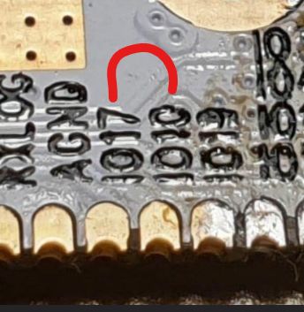
    is there continuity between IO10 and IO17 on the one that doesn't work? tiny bit of solder linking the two?

    Close-up of PCB pin labels with a red U-shaped marker drawn on it
  • #28 21705019
    LeMaxime
    Level 7  
    >>21704896
    lmao, i found that i broke 2 pads on first bulb- IO17 and IO19
    repaired them and now brightess control available on both bulbs

    but still few funny things
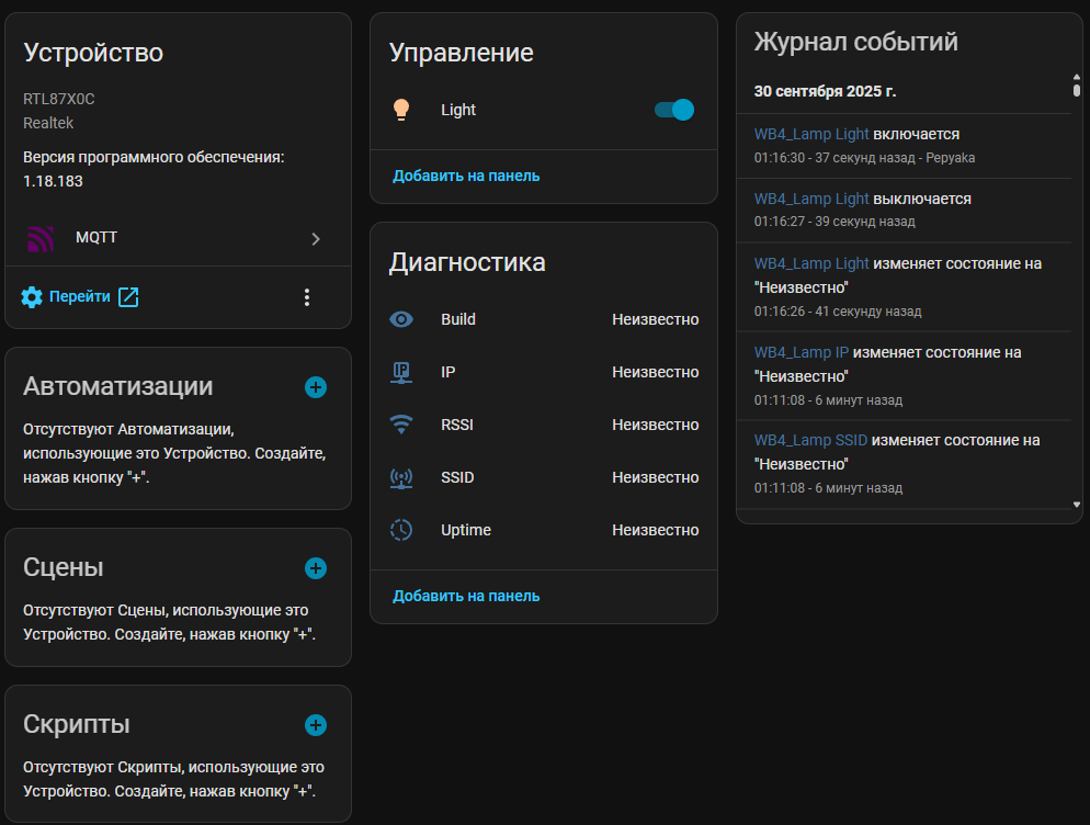
    1)If i use Flag 24 - LED Temperature Slider control RGB LEDs(that slider turn on RGB LEDs and setting them to white color) and control thier brightness,in Home Assistant i see bulb entity and can control colors and brightness RGB LEDs -
    Spoiler:
    IoT device interface showing diagnostics, controls, and light switch status

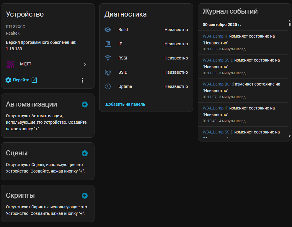
    2)If i disable Flag 24 - LED Temparature Slider control white LEDs brightness, but there is no bulb entity in Home Assistant -
    Spoiler:
    Interface panel showing RTL87XXC device info, diagnostics, and event log


    But if firstly i set Flag 24 and after remove him - control still appears in Home Assistant and EVEN i can choose white LEDs and control their brightness
    so funny
  • #30 21708972
    LeMaxime
    Level 7  
    I've updated my post a bit, I hope it helps those who want to flash this light bulb.

Topic summary

The discussion addresses difficulties flashing Tasmota firmware on the Gosund Nite Bird WB4 smart bulb due to lack of communication feedback from the controller despite soldered leads. The bulb's internal board appears similar to older versions but lacks labeled pins, suggesting a possible hardware revision. It is noted that the manufacturer may have replaced the original ESP WiFi module with a W701H variant, complicating detection and flashing. The W701H module, also referenced as CUCO-KK-R-V1.2, requires specific pin connections for flashing: VDD33 to 3.3V, AGND to ground, TXLOG to RX, RXLOG to TX, with RX (GPIO13) and IO0 pulled to 3.3V continuously to enter flashing mode, and CEN momentarily grounded to reset. Additional resources include pinout guides and datasheets for WBR2, WBR3, WBRU, and W701-VA2-CG chips, which are relevant for Home Assistant integration and firmware flashing.
Summary generated by the language model.
ADVERTISEMENT