logo elektroda
logo elektroda
X
logo elektroda

[Solved] How to connect 3.3V USB-TTL to UPXNBOR CB2S LN882HKI for OpenBeken?

FranzBiberkopf 360 8
ADVERTISEMENT
  • LN882HKI pinout and missing capacitor pads explained

    #1 21937707
    FranzBiberkopf
    Level 2  
    Posts: 8
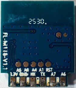
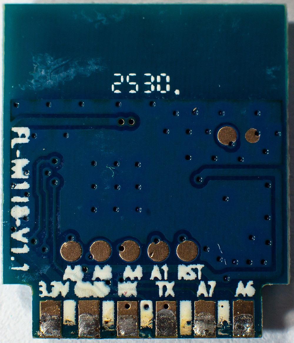
    I am here after buying an UPXNBOR plug expecting to get another esp device for Tasmota. After teardown - which is fortunately still very easy with those plugs - I learned that it has no longer an Esp chip in, but an LN882HKI. I desoldered the chip, as the prints on the pins are very ugly and almost not to read, while it is soldered in. But even when I have this chip in front of me, the prints are very bad.
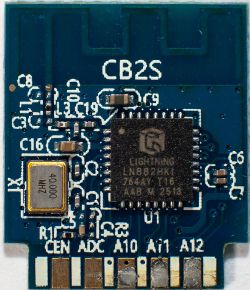
    How to connect 3.3V USB-TTL to UPXNBOR CB2S LN882HKI for OpenBeken? How to connect 3.3V USB-TTL to UPXNBOR CB2S LN882HKI for OpenBeken?
    I learned now that OpenBeken would be the way to go, as this should work similar to my Tasmota devices.
    First question here:
    Where do I have to solder which pins from my 3.3 V USB-TTL adapter?
    Which pin can I use for connecting a buzzer to?

    Thanks for any useful hints on how I can proceed without damaging the µC.

    Edit:
    When watching now my pictures I have shot for this post, another question arised:
    Why are C3, C4, C5 and C8 not placed and contain empty solder pads?

    More questions arise:
    Is the 3V3 50mA output from an FT232 adapter enough to power such an desoldered chip? Or does the µC needs higher current?

    Added after 5 [hours] 31 [minutes]:

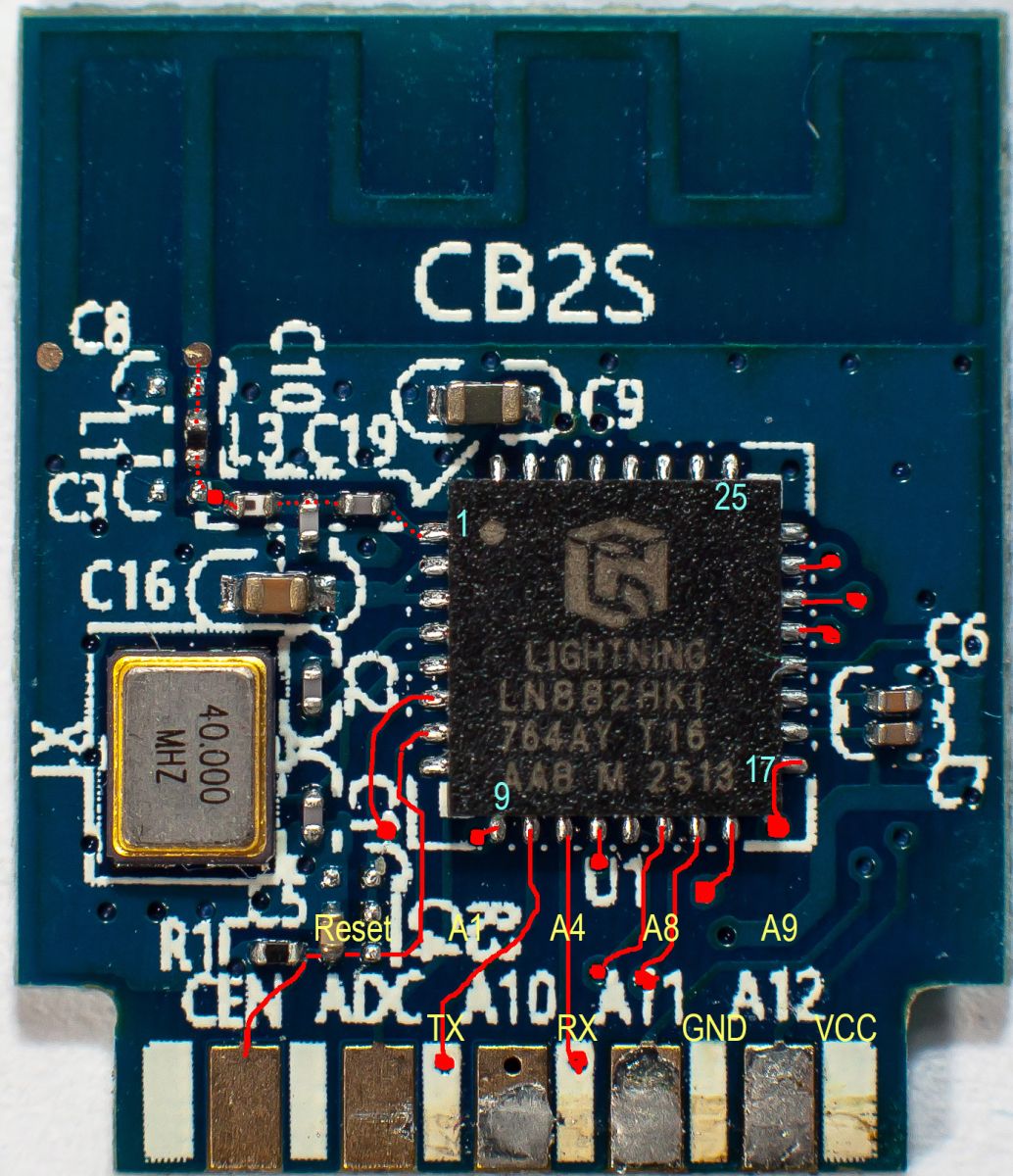
    Ok, did some more research, found the datasheet and looked closer to the device. I marked some traces and vias and created an transparent mirrored overlay of the backside, to get an better overview, what is routed where.
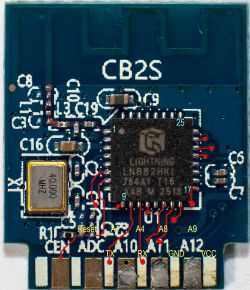
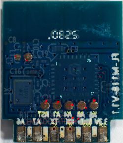
    How to connect 3.3V USB-TTL to UPXNBOR CB2S LN882HKI for OpenBeken?How to connect 3.3V USB-TTL to UPXNBOR CB2S LN882HKI for OpenBeken?


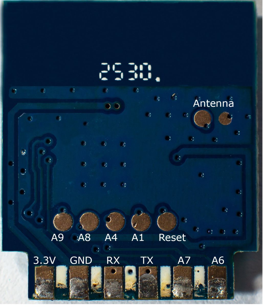
    I was shocked reading in the datasheet, that there are up to three UARTs, but they have no hard defined pin, pins could be mapped to each IO-pin. However, I found some articles, telling me, that initially TX maps to A2, which is Pin10, RX maps to A3, which is Pin11. As the mapping for the readable TX with Pin10 is correct, I labeled the neighbour-pin connected to pin 11 RX

    So still waiting for some responses before I fry the µC, by wronmg assumptions.
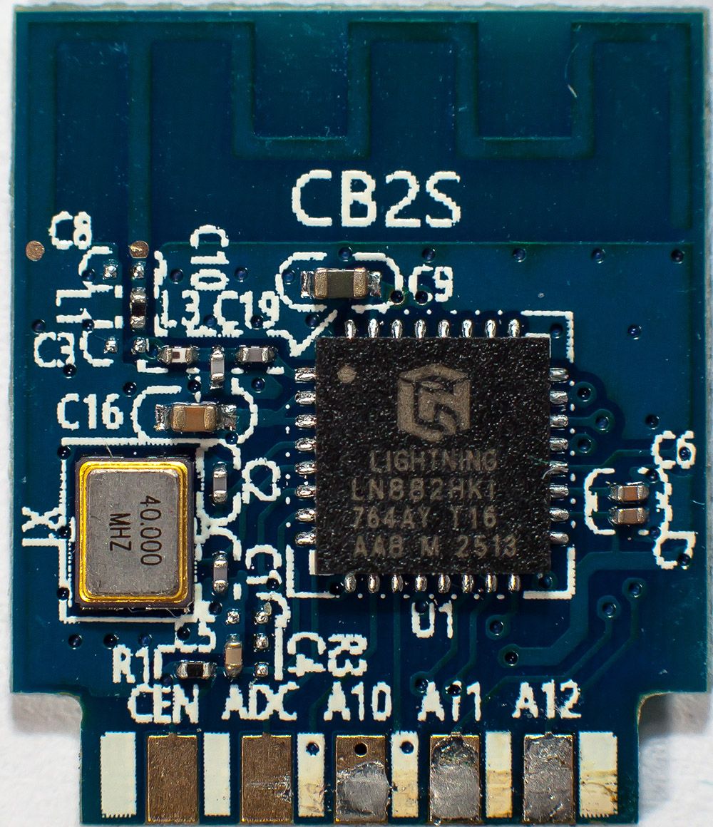
  • ADVERTISEMENT
  • Flash succeeded; current draw suggests FT232 may suffice

    #3 21938272
    FranzBiberkopf
    Level 2  
    Posts: 8
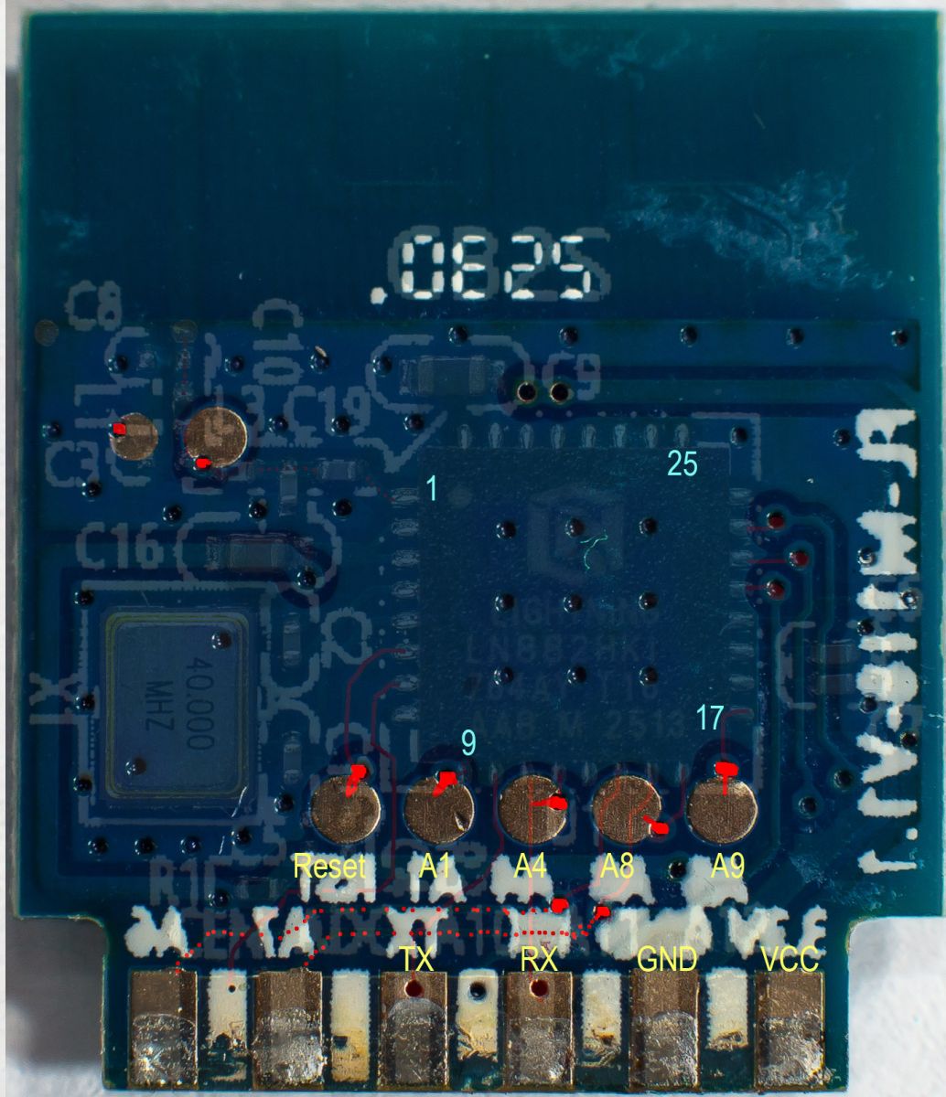
    OK, I was now able to flash, after identifying A9. I checked especially the backside to identify all those pads, and updated the backside picture:
    How to connect 3.3V USB-TTL to UPXNBOR CB2S LN882HKI for OpenBeken?
    During flash I got this message:
    It's not an OBK config, header is bad
    OBK config not found

    Then a window opened, which showed me the downloaded configuration and this message in parallel window:
    Sorry, no meaningful pins data found. This device may be TuyaMCU or a custom one with no Tuya config data.
    No module information found.
    And the Tuya section starts at 2015232 (0x1EC000), which is a default LN882H offset.

    One important observation: I had the device connected to a separate power supply and saw that the current drawn during flash was 47mA-48mA, so it should be possible to flash with only an FT232, which can deliver 50mA. In this case, the 3.3V should be stabilised for short peaks with a 47µ electrolytic. No bigger one, as otherwise the inrush current of the cap can kill the FT232. I will try this with my next flash. But that will happen first, when I get the device fully working.
    So I need to get information, how I have to configure this plug.
    As mentioned in first post, it is an UPXNBOR, model No. XT03
    If someone has more information, all infos are highly welcome.

    Added after 40 [minutes]:

    OOps, I realize OpenBeken is not the way to go!
    I can't create that it starts an secure Wifi-AP! This is incredible awful, as this is a needed condition in my case.
    Each simple ESP is able to do that. Why this is not possible here?
  • ADVERTISEMENT
  • #4 21938589
    divadiow
    Level 38  
    Posts: 5177
    Help: 443
    Rate: 908
    is the issue that connecting to an open AP (no password required) for initial setup is not an option for you?
  • Need for standalone WPA2 AP or WPA2-Enterprise support

    #5 21938644
    FranzBiberkopf
    Level 2  
    Posts: 8
    No, I need to run this device standalone with recent WPA2 encryption. And now I even learned that setting an admin password for basic authentication and leaving the remaining configuration empty breaks the further configuration of this device!

    The device must run without any external dependency. For configuration, you must be able to connect to its WPA2-AP.
    That is how all Tasmota/ESPurna things work here, and I learned that OpenBeken should be almost a Tasmota replacement. But this is an enormous shortcoming!

    As this device is not able to log in to a WPA2-Enterprise AP, running its own WPA2 AP without routing between connected devices, this is the only possible option through security constraints.

    I tried many tricks. I found that trying to set the secure AP through an autoexec.bat and "Startup Command Text" did not work with the most recent version.

    Can I enable a secure AP and break this absurd lock to unsecurity by compiling it myself?

    Having such a device with stored SSID/PWD for a WPA2 network is regarded like putting a WLAN pwd to the public, if the device is in a location where it can just be stolen or "borrowed" for a short time. Therefore no general WLANs are here allowed, as this is the only way to prevent that. If a WPA2-Enterprise ID gets into wrong hands, it is

    - clear whom it was stolen from or who shared it
    - it's easily detectable, by (tried) logins to an AP where this user should not log in or too many parallel logins
    - only one account can be easily disabled.

    Furthermore, you can throw connections in special networks, where it is clearly handled what is allowed for and to this connection.

    So in short: To use OpenBeken it must act as a secure WPA2-AP or attach to a WLAN through WPA2-Enterprise, with SSID, Username, Password.
  • ADVERTISEMENT
  • Device pinout for UPXNBOR XT03 with LN882HKI

    #7 21938949
    FranzBiberkopf
    Level 2  
    Posts: 8
    What is the reason that this possibility is strictly removed? Also no way for configuration through console etc., if it should be kept out from Web-UI?

    Added after 2 [hours] 43 [minutes]:

    Just to complete the informations about the device, after I got the device working.
    Manufacturer/Brand: UPXNBOR
    Model No: XT03
    Chip: LN882HKI
    Button No.Button function
    3Btn
    6 BL0937SEL
    7 LED_n
    10 BL0937CF
    11 Rel
    12 BL0937CF1


    Added after 1 [hours] 25 [minutes]:

    More information retrieved: The power is generated in two steps: First a BP2525 configured to output 5V, it is the D-Type capable of 300mA steady current with 500mA peak.
    That is followed by a powerful AMS1117 3.3V, which could output more current, than the BP2525 can deliver.
  • ADVERTISEMENT
  • #8 21940217
    FranzBiberkopf
    Level 2  
    Posts: 8
    Will close this thread, as I can connect. Will open new threads for other questions.
  • #9 21940219
    FranzBiberkopf
    Level 2  
    Posts: 8
    As described in the thread above. As I can connect, other questions belong to other threads.

Topic summary

✨ The discussion concerns an UPXNBOR smart plug that uses an LN882HKI chip instead of an ESP device, with the goal of flashing OpenBeken. The chip was desoldered because the pin markings were hard to read. The key guidance provided is that the LN882H must first be placed into boot mode by pulling A9 to GND, after which flash read/write can be performed using the BK7231GUIFlashTool.
AI summary based on the discussion. May contain errors.
ADVERTISEMENT