Here I'll take a look inside a generic Tuya-based UK smart plug with energy metering. The Tuya firmware on the main chip will be replaced with OpenBeken.
This plug can be bought from Ali Express
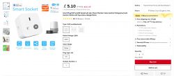
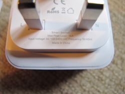
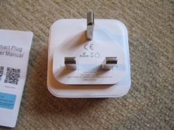
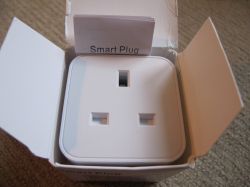
Packaging and product externals:
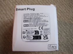
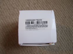
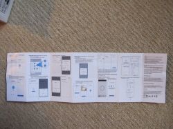
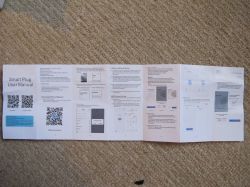
To open, I trapped the plug in a vice below the joining lip/edge knowing that that's where the two main case pieces would be glued. With some decent, but not extreme, clamping the glue can be heard to give way and crack apart. A thin spudger helps it along. Rotate unit so different points are put under pressure until the glue is cracked in more places than not and the unit can be pulled apart by hand. My device was not glued well so this sample was relatively easy compared to some.
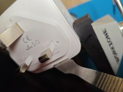
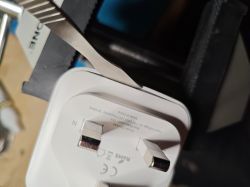
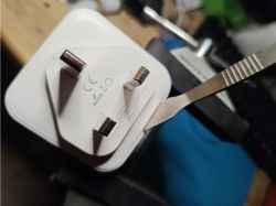
Now that we're inside:
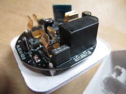
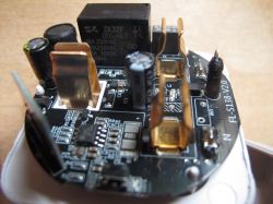
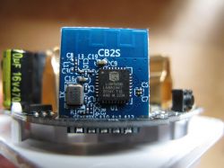
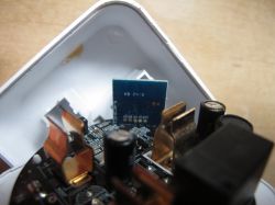
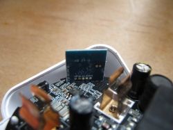
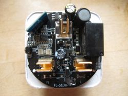
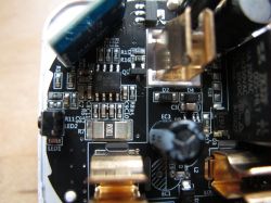
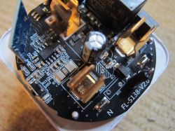
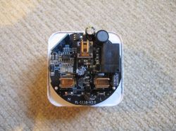
Some identified main components of interest:
Belling BL0937 energy metering chip
FL-M118-V1.1 Lightning Semi Conductor LN882HKI module
ZK32F 005-HLT 16A@250VAC Shenzhen Zhongke Zhilian Electronics Co.,Ltd. relay
Main PCB marked as FL-S138-V2.0
AMS1117-3.3v linear voltage regulator
The FL-M118-V1.1 module is what we need access to. We need to get to certain contacts on the module to be able to take a backup of the Tuya factory firmware and flash OpenBeken (OpenLN882H).
Unfortunately RX, TX, 3.3v and GND module contacts are at the rear underside facing the centre of the plug - inaccessible without de-soldering the main PCB from the power prongs.
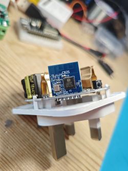
To de-solder I added some flux to the solder points and then melted some 63/37 pb solder into the mix to reduce the melting point of the solder used by the factory

This process was laborious because the whole power prong draws heat away from the solder point quickly, meaning it has to heat up a lot to get to melting point. Solder wick was used to soak up most of the solder but some stubborn bits remained - keeping the unit fixed in place. Switching sides slowly inching each upwards when melted was the solution.
With the main PCB free the FL-M118-V1.1 can be de-soldered also using wick/pb/flux.
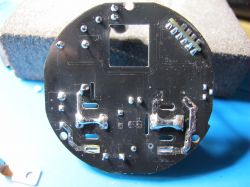
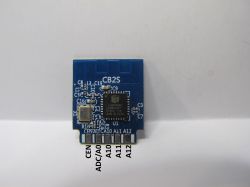
The "CB2S" label is...interesting. "CB2S" is of course usually reserved for Beken BK7231N modules . This LN882H is a drop-in pad-compatible replacement for CB2S, so maybe that's the link trying to be made. I've labelled all pads for clarity:
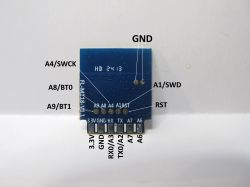
RX/TX/VCC/GND and A9 (needs to be grounded for the flashing boot mode) all soldered ready:
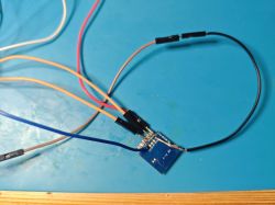
Connect to USB-TTL UART adaptor as:
USB-TTL RX -> Module TX
USB-TTL TX -> Module RX
External 3.3V PSU (XL4015 in my case) -> Module 3.3V
USB-TTL GND + Module GND + A9 + PSU GND (all common ground)
Insert USB adaptor then power on PSU. Using the attached flashdumper.py script in the attached zip the following was run to start the backup
After approximately 40 minutes the backup is complete - two files are output <filename>.bin and <filename>_otp.bin
the main backup file should be exactly 2,097,152 bytes.
Power off, unplug USB, replug USB and power on PSU so OpenLN can be flashed. Using the steps outlined in here we can flash the latest LN882H UART flash file.
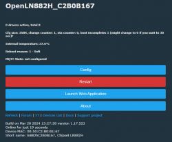
Without A9 grounded the next power-up of the module should lead to an AP broadcast that can be connected to in the browser on 192.168.4.1 after joining to AP. From there OpenBeken can be joined to your wifi through the Config-> Configure Wi-Fi & Web menu. After reboot check you can browse to the DHCP-assigned IP of your device.

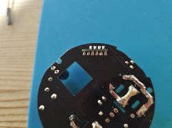
With the module back in the empty slot on the main PCB, stabilised with a bit of blu-tac, the module can be soldered back. Plenty of flux and small solder blobs, especially with the ground pad which tends to be wider and requires a little more contact to heat up. I have had to de-solder the whole module again in the past before because the ground blob has splurged into neighbouring pads and I couldn't clear it with wick. I always check there isn't continuity between contacts when soldering is complete.
The result after clearing up flux residue with IPA:
After clearing any remaining solder from the main PCB holes, the unit can be soldered back together in position
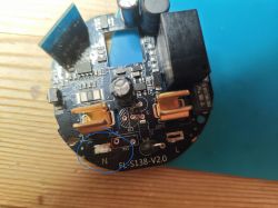
What remains now is to configure the BL0937, LED, button and relay roles within OpenBeken so the plug is fully operational, exactly like or close to factory behaviour.
Through the use of the GPIO doctor, multimeter continuity tracing and a process of elimination (GPIO options are limited to just a few on this module), the following has been determined and tested to work;
which makes the whole template, which can be imported through the web application the following:
BL0937 metering can be calibrated as per this post: https://www.elektroda.com/rtvforum/topic4030107.html#20920434
What remains:
Epoxy resin glue plug casing back together
Setup MQTT/Home Assistant https://youtu.be/pkcspey25V4?si=hPcIBAFMfHqR22sa
Ensure PowerSave 1 is set in startup command or autoexec.bat:
https://github.com/openshwprojects/OpenBK7231T_App/blob/main/docs/autoexecExamples.md
https://github.com/openshwprojects/OpenBK7231T_App/blob/main/docs/commands-extended.md
Notes since initial draft
I note that the main PCB Marking starts FL- (FL-S138-V2.0) as does the marking on the module (FL-M118-V1.1). The name on one of the stickers on the box is for a Shenzhen Farylink Technology Co.,Ltd. It would be reasonable to assume FL = Farylink, also the store on Ali Express it was bought from. I don't think it would be a stretch to assume similarly-named modules like the FL-M61 V2, FL_M99_V1/2/3 are all Farylink.
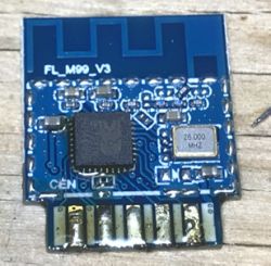
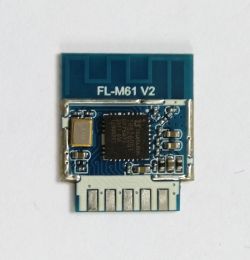
How to flash FL_M99_V1/FL_M99_V2/FL_M99_V3/CB2S WiFi module - BK7231N Tuya Home Assistant guide
https://fcc.report/company/Shenzhen-Farylink-Technology-Co-L-T-D
UART boot log B9 is not routed out to a pad on the module so I had to use my sewing needle probe to capture the log, which is:
The factory firmware backup is file Tuya_3.5.4_Farylink-UK_Plug_(Smart-Plug-schemaID-g2xobg)_cptnnkbvpdxkkcvy_FL-M118-V1.1_1.0.0.bin at https://github.com/openshwprojects/FlashDumps/tree/main/IoT/LN882H
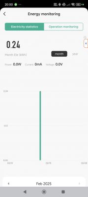
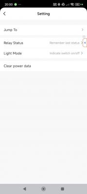
Tuya app paired device pics
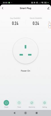
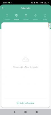
This plug can be bought from Ali Express

Packaging and product externals:


To open, I trapped the plug in a vice below the joining lip/edge knowing that that's where the two main case pieces would be glued. With some decent, but not extreme, clamping the glue can be heard to give way and crack apart. A thin spudger helps it along. Rotate unit so different points are put under pressure until the glue is cracked in more places than not and the unit can be pulled apart by hand. My device was not glued well so this sample was relatively easy compared to some.


Now that we're inside:


Some identified main components of interest:
Belling BL0937 energy metering chip
FL-M118-V1.1 Lightning Semi Conductor LN882HKI module
ZK32F 005-HLT 16A@250VAC Shenzhen Zhongke Zhilian Electronics Co.,Ltd. relay
Main PCB marked as FL-S138-V2.0
AMS1117-3.3v linear voltage regulator
The FL-M118-V1.1 module is what we need access to. We need to get to certain contacts on the module to be able to take a backup of the Tuya factory firmware and flash OpenBeken (OpenLN882H).
Unfortunately RX, TX, 3.3v and GND module contacts are at the rear underside facing the centre of the plug - inaccessible without de-soldering the main PCB from the power prongs.

To de-solder I added some flux to the solder points and then melted some 63/37 pb solder into the mix to reduce the melting point of the solder used by the factory

This process was laborious because the whole power prong draws heat away from the solder point quickly, meaning it has to heat up a lot to get to melting point. Solder wick was used to soak up most of the solder but some stubborn bits remained - keeping the unit fixed in place. Switching sides slowly inching each upwards when melted was the solution.
With the main PCB free the FL-M118-V1.1 can be de-soldered also using wick/pb/flux.

The "CB2S" label is...interesting. "CB2S" is of course usually reserved for Beken BK7231N modules . This LN882H is a drop-in pad-compatible replacement for CB2S, so maybe that's the link trying to be made. I've labelled all pads for clarity:


RX/TX/VCC/GND and A9 (needs to be grounded for the flashing boot mode) all soldered ready:

Connect to USB-TTL UART adaptor as:
USB-TTL RX -> Module TX
USB-TTL TX -> Module RX
External 3.3V PSU (XL4015 in my case) -> Module 3.3V
USB-TTL GND + Module GND + A9 + PSU GND (all common ground)
Insert USB adaptor then power on PSU. Using the attached flashdumper.py script in the attached zip the following was run to start the backup
Code: Text
After approximately 40 minutes the backup is complete - two files are output <filename>.bin and <filename>_otp.bin
the main backup file should be exactly 2,097,152 bytes.
Power off, unplug USB, replug USB and power on PSU so OpenLN can be flashed. Using the steps outlined in here we can flash the latest LN882H UART flash file.
Without A9 grounded the next power-up of the module should lead to an AP broadcast that can be connected to in the browser on 192.168.4.1 after joining to AP. From there OpenBeken can be joined to your wifi through the Config-> Configure Wi-Fi & Web menu. After reboot check you can browse to the DHCP-assigned IP of your device.


With the module back in the empty slot on the main PCB, stabilised with a bit of blu-tac, the module can be soldered back. Plenty of flux and small solder blobs, especially with the ground pad which tends to be wider and requires a little more contact to heat up. I have had to de-solder the whole module again in the past before because the ground blob has splurged into neighbouring pads and I couldn't clear it with wick. I always check there isn't continuity between contacts when soldering is complete.
The result after clearing up flux residue with IPA:

After clearing any remaining solder from the main PCB holes, the unit can be soldered back together in position

What remains now is to configure the BL0937, LED, button and relay roles within OpenBeken so the plug is fully operational, exactly like or close to factory behaviour.
Through the use of the GPIO doctor, multimeter continuity tracing and a process of elimination (GPIO options are limited to just a few on this module), the following has been determined and tested to work;
Code: Text
which makes the whole template, which can be imported through the web application the following:
Code: JSON
BL0937 metering can be calibrated as per this post: https://www.elektroda.com/rtvforum/topic4030107.html#20920434
What remains:
Epoxy resin glue plug casing back together
Setup MQTT/Home Assistant https://youtu.be/pkcspey25V4?si=hPcIBAFMfHqR22sa
Ensure PowerSave 1 is set in startup command or autoexec.bat:
https://github.com/openshwprojects/OpenBK7231T_App/blob/main/docs/autoexecExamples.md
https://github.com/openshwprojects/OpenBK7231T_App/blob/main/docs/commands-extended.md
Notes since initial draft
I note that the main PCB Marking starts FL- (FL-S138-V2.0) as does the marking on the module (FL-M118-V1.1). The name on one of the stickers on the box is for a Shenzhen Farylink Technology Co.,Ltd. It would be reasonable to assume FL = Farylink, also the store on Ali Express it was bought from. I don't think it would be a stretch to assume similarly-named modules like the FL-M61 V2, FL_M99_V1/2/3 are all Farylink.


How to flash FL_M99_V1/FL_M99_V2/FL_M99_V3/CB2S WiFi module - BK7231N Tuya Home Assistant guide
https://fcc.report/company/Shenzhen-Farylink-Technology-Co-L-T-D
UART boot log B9 is not routed out to a pad on the module so I had to use my sewing needle probe to capture the log, which is:
Code: Text
The factory firmware backup is file Tuya_3.5.4_Farylink-UK_Plug_(Smart-Plug-schemaID-g2xobg)_cptnnkbvpdxkkcvy_FL-M118-V1.1_1.0.0.bin at https://github.com/openshwprojects/FlashDumps/tree/main/IoT/LN882H
Tuya app paired device pics


Cool? Ranking DIY


