
Chronocomparator - vibroscope.
It is a device that helps to set the correct gait of clocks and mechanical watches.
It allows you to check whether the watch is working correctly both in the face down, up or on the side.
Is the gait stability maintained over a longer period of time, e.g. several hours after application?
In the case of large clocks, the analysis of the graph of uneven gait - periodic acceleration and deceleration, allows you to locate the troubling racks.
The project does not aspire to compete with professional (and very expensive) devices.
It is intended for hobbyists - collectors of watches. It is a pocket, portable version of the device - the Biburo program, which requires the use of a computer to work.
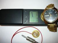
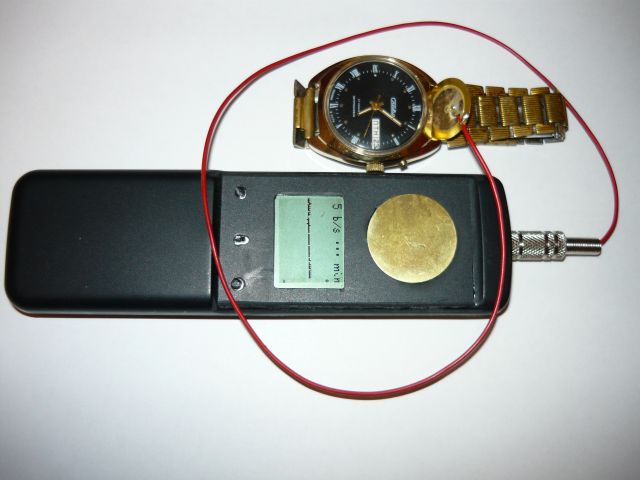
The chronocomparator works by sensing the ticking of a watch (its mechanical vibrations) with a piezoelectric transducer.
The pulses from this transducer, after appropriate amplification and shaping, are compared with the reference reference pulses.
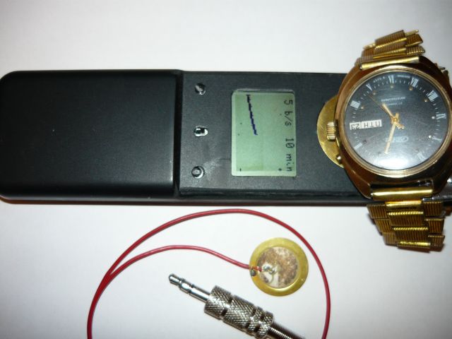
The change in phase shift between these pulses is visualized graphically on the LCD display.
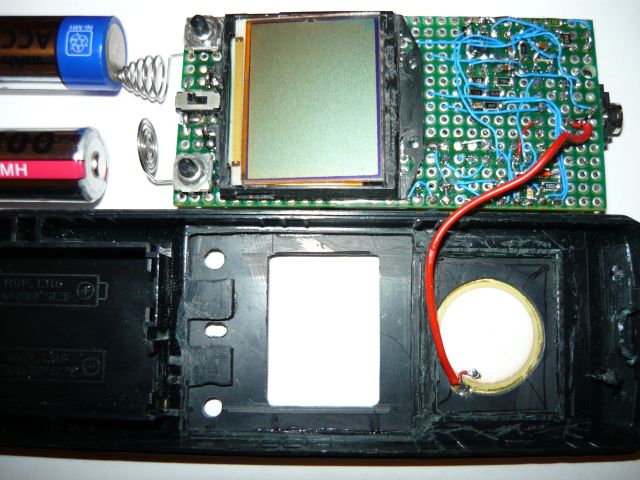
The project uses a monochrome display with a resolution of 84x48 pixels from Nokia 5210.
The chrono-comparator is adapted to clocks with the number of ticks per second:
1 b / s, 1i1 / 2 b / s, 3i1 / 3 b / s, 4i1 / 2 b / s, 5 b / s, 5i1 / 2 b / s, 6 b / s, 8 b / s, 10 b / s.
It takes 10 minutes, 60 minutes and 360 minutes to fill the screen. There is also the direct range where each tick is directly represented on the screen.
When the screen is full, the graph is redrawn from the left side of the screen.
Parameter changes are made using two buttons.
The "heart" of the device is the popular PIC16F84A processor, working with an external 7.3728 MHz quartz resonator.
Since it is a time standard for the tested watches, its frequency should be carefully set by selecting capacitors with a capacity of about 30 pF working with it.
The processor was mounted without a socket, so the ICSP connector for programming the processor was also installed.
The software was written in the GCB (Great Cow Basic) environment.
Particular emphasis was placed on the proper handling of interrupts from the internal timer T0, and especially on determining the correct moment of loading the T0 register.
The interrupt period is 1/40 of the clock tick period of the set range.
During this time, the processor checks for a tick and possibly lights the current pixel in the current column.
The graphical chart is 80 columns long, with 40 pixels per column.
The processor and the LCD display are supplied with the voltage of 3.3V.
To amplify the signals from the piezoelectric transducer I used the LM324 system, i.e. a quad operational amplifier.
Three of them are a high gain band shaping amplifier, while the fourth is a monostable pulse generator.
The amplifier is powered by a single positive voltage of 5V.
The old remote control with its battery basket was used as the case of the chronocomparator.
The power supply is provided by two AA cells or two NiMH batteries, providing a voltage of about 2.4 V to 3V.
This voltage is raised to 5V using the MAX1674 converter.
In turn, the voltage of 3.3V for the processor and the display comes from the LM1117 stabilizer.
Converterpiezoelectric was placed on top of the chronocomparator case - glued over the round hole.
The chronocomparator is also equipped with an input socket for connecting an external transducer.
The socket is also supplied with 5V voltage, which enables powering an additional external amplifier.
The external sensor is more convenient to use when examining large clocks, small watches can be placed on top of the sensor on the housing.
It is best when the crown of the watch touches the sensor.
The diagram of the device has been created so far only in pencil for my own needs, a decent diagram requires a lot of work, and I do not know if the presented topic will generate interest.
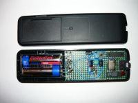

As you can see in the photos attached, the device was made on a universal PCB, using mainly SMD components, and Kynar connections.
I estimate the cost of subassemblies at several to several dozen zlotys, depending on what the contractor uses from his own stocks or recovers from old systems.

Comments
A completely new topic for me, I think that even a pencil diagram will be useful, it is worth putting a video presenting the operation of the device, and maybe a timelapse because from what I can see... [Read more]
An interesting and practical project. I would love to see a schematic of the amplifier circuit. I am planning a project where I will use a piezoelectric transducer, so I am interested in various solut... [Read more]
Sorry to be quite messy, but I am enclosing a "pencil" scan. Additionally, I attach the hex file to the processor - change the extension to hex. Display notes: The Nokia5210 display is almost compatible... [Read more]
I remember that someone here once commissioned such a device. [Read more]
A very nice device, but .... If I were a colleague, I would add a computer output (via USB or Audio) for data archiving. In addition, I would make an analyzer of the entire acoustic spectrum generated... [Read more]
Buddy, Krzysztof. It was supposed to be a small, pocket-sized device that would work independently. A colleague proposes to make the entire combine, preferably connected to a data dump computer. ... [Read more]
For the record: Chronocomparator for checking the movement of watches - "Radioelektronik" 3/91. [Read more]
[video: 1a89858be4] https://filmy.elektroda.pl/19_1495014417.mp4 [/ video: 1a89858be4] I am enclosing a video showing the operation of the chrono comparator and the change of working ranges. [Read more]
Cool design. If you refined it, put the batch in an editable version (with the possibility of changing it to some ATMEGA), there would certainly be a few people who would like to make such a device for... [Read more]
The project is quite complete, but I have a question whether a pattern could be used for the Prock timing, I mean the DS32 kHz chip, because the quartz chrono seems to me not very accurate. Maybe I don't... [Read more]
For watches with mechanical escapement, this is quite sufficient, nothing prevents you from using the rubidium standard. [Read more]
In my opinion, in a pocket device for checking the gait of mechanical watches, for which a daily accuracy of + -10 seconds is an achievement, the standard with a quartz resonator is perfectly sufficient.... [Read more]
Maybe a "lame" question, but after the title I was expecting a frequency meter and here some lines on the LCD ;-) . Maybe a colleague will suggest how such indications are interpreted? Maybe some examples... [Read more]
Great design. I am one of the creators of Great Cow BASIC. Can you publish the source code for others to learn? And on the question of porting to ATMEGA (Arduino I suppose) it's relatively... [Read more]
That's right, porting to Atmega is easy with the source code. For now, however, only the code in a compiled form for a specific layout is available. [Read more]
Excuse me. I thought you made a program in Great Cow BASIC, therefore I thought you had the source code. My mistake. Excuse me. ******************* english So sorry. I thought you created the program... [Read more]
I present the source code of the chronocomparator program. It is written in GreatCowBasic. Those willing to transfer the program from the PIC16F84A processor to another processor, such as an Atmega,... [Read more]
Pytanko - does the device show the type of error? Let's say abnormal tick, double tick. It would be nice, but probably hard to make an angle analyzer on the clock hand, here I suspect some script for... [Read more]
The described chronocomparator is a fairly simple device, it only shows the irregularity of gait and helps to set the correct gait of the clock. I also made a more elaborate one with an oscilloscope... [Read more]