Construction description
The tester was created to learn how to draw patterns in Eagle and learn the basics of microprocessor programming. In addition, it is small in size. I used SMD components for the first time.
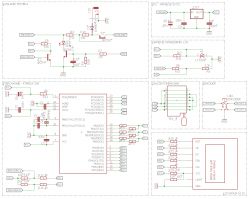
Scheme:
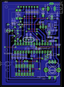
PCB view from EAGLE:
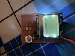
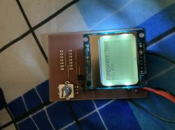
Here are the pictures of the finished structure:
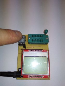
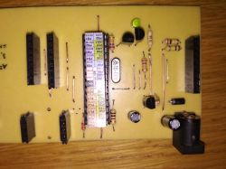
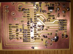
To facilitate the exchange of the ZIF14 processor and socket, they were placed in the sockets.
In addition, the ZIF socket and the encoder should be above the LCD to simplify assembly of the whole in the housing.
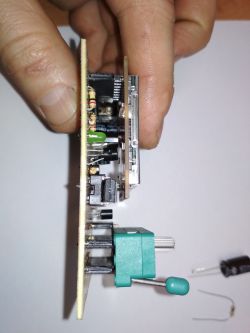
The whole structure was made as described on the pages:
Link
Link
The housing of the tester and possible attachments extending its capabilities remained. In addition, you need to protect the paths with, for example, transparent lacquer. For details, I refer to the links above.
It is a well-known construction of the electrode, a novelty is the use of a display from Nokia 5110/3110.
I used 680om and 470kom measuring resistors with a tolerance of 0.1%.
In the software I also entered the exact value of the reference voltage in mV. TL431 reference voltage with a tolerance of 1%. The reference voltage measurement showed 2491mV. This value has been entered in the microprocessor program.
The construction is not without the drawbacks:
- the LED signaling work is located under the LCD (my conscious decision),
- lack of LCD backlight (I found them unnecessary),
- power supply from the 12V power supply (you can easily convert the whole and use a 9V battery),
- execution leaves much to be improved (especially SMD in February).
Here are some videos showing how the tester works:
Attached in the attachment:
1. A diagram in EAGLE with a drawing of paths.
2. A diagram with a drawing of paths in PDF.
3. Compiled source files of the software version 1.31m.
Fusebit settings:

For now, I tested what I have in the drawer and the results come close to measurements by the Chinese ANENG 102 and more familiar and valued UNI-T UT71.
By the way, I can mention that the Chinese meter does not differ by measurements from UNI-T.
Estimate of the constructed structure:
Atmega328 PLN 6
PCB (chemistry for etching) ~ 5 PLN
ZIF14 socket ~ 2 PLN
Nokia5110 display ~ 6 PLN
capacitors, resistors, goldpins ~ 5 PLN
precision resistors 680om, 470kom 0.1% ~ 3 PLN
power socket, encoder, stabilizer ~ 4 PLN
-------------------------------------------------- -------
The whole is about PLN 20 (purchases made on Aliexpress).
In the comments, I ask for constructive criticism, information, what should be improved, etc.
If anyone is interested in additional materials, please contact PW.
The tester was created to learn how to draw patterns in Eagle and learn the basics of microprocessor programming. In addition, it is small in size. I used SMD components for the first time.
Scheme:

PCB view from EAGLE:

Here are the pictures of the finished structure:


To facilitate the exchange of the ZIF14 processor and socket, they were placed in the sockets.
In addition, the ZIF socket and the encoder should be above the LCD to simplify assembly of the whole in the housing.

The whole structure was made as described on the pages:
Link
Link
The housing of the tester and possible attachments extending its capabilities remained. In addition, you need to protect the paths with, for example, transparent lacquer. For details, I refer to the links above.
It is a well-known construction of the electrode, a novelty is the use of a display from Nokia 5110/3110.
I used 680om and 470kom measuring resistors with a tolerance of 0.1%.
In the software I also entered the exact value of the reference voltage in mV. TL431 reference voltage with a tolerance of 1%. The reference voltage measurement showed 2491mV. This value has been entered in the microprocessor program.
The construction is not without the drawbacks:
- the LED signaling work is located under the LCD (my conscious decision),
- lack of LCD backlight (I found them unnecessary),
- power supply from the 12V power supply (you can easily convert the whole and use a 9V battery),
- execution leaves much to be improved (especially SMD in February).
Here are some videos showing how the tester works:
Attached in the attachment:
1. A diagram in EAGLE with a drawing of paths.
2. A diagram with a drawing of paths in PDF.
3. Compiled source files of the software version 1.31m.
Fusebit settings:

For now, I tested what I have in the drawer and the results come close to measurements by the Chinese ANENG 102 and more familiar and valued UNI-T UT71.
By the way, I can mention that the Chinese meter does not differ by measurements from UNI-T.
Estimate of the constructed structure:
Atmega328 PLN 6
PCB (chemistry for etching) ~ 5 PLN
ZIF14 socket ~ 2 PLN
Nokia5110 display ~ 6 PLN
capacitors, resistors, goldpins ~ 5 PLN
precision resistors 680om, 470kom 0.1% ~ 3 PLN
power socket, encoder, stabilizer ~ 4 PLN
-------------------------------------------------- -------
The whole is about PLN 20 (purchases made on Aliexpress).
In the comments, I ask for constructive criticism, information, what should be improved, etc.
If anyone is interested in additional materials, please contact PW.
Cool? Ranking DIY


