Hello.
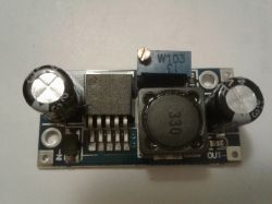
Below I present a description of the step-down converter based on the LM2596S-ADJ chip.
The prices of the converter start on Aliexpress from less than $ 0.60 with shipping, prices with shipping on Polish auction portals start from about PLN 7.
The maximum input voltage for the converter is 35 V (the converter IC itself can withstand a higher voltage, but the limitation here is the electrolytic capacitor at the input, which here has 35 V - you can find converters with a 50 V capacitor).
The output voltage is regulated by a potentiometer in the range from 3.2 to 35 V, efficiency up to approx. 3 A.
Converter dimensions: 44 x 20 x 13 mm
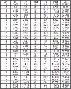
The converter was tested with an artificial load for input voltages of 12, 15 and 24 V and for output voltages of 12 and 5 V. During the tests, voltages and currents on the input and output sides of the converter were measured, power and efficiency were calculated.
Below I present the measurement results.
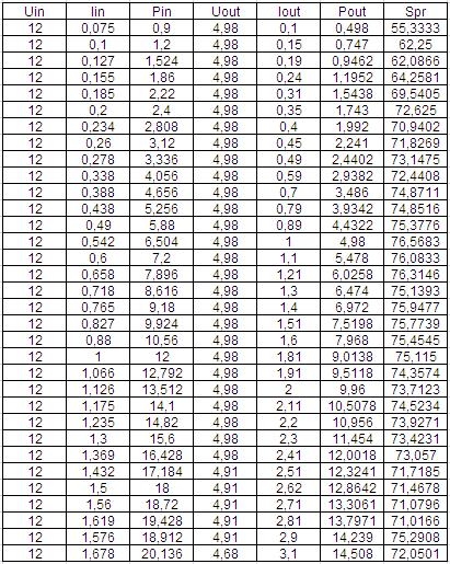
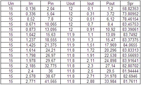
Input voltage 12V, output voltage 5V:
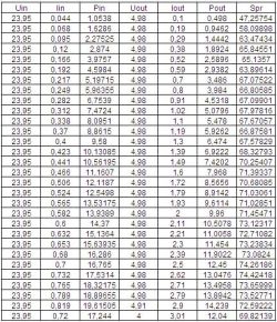
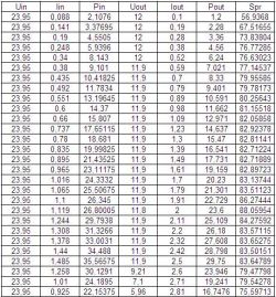
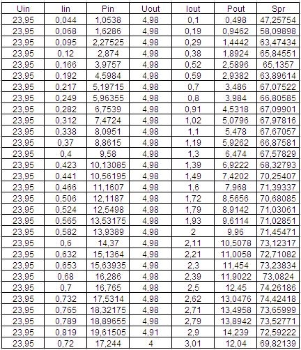
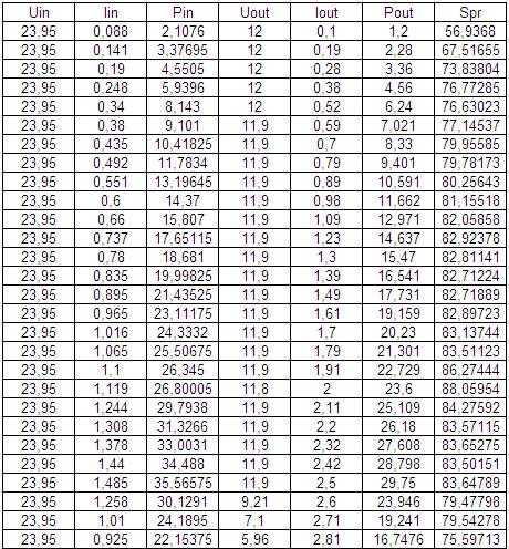
Input voltage 24V, output voltage 5V:
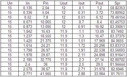
Input voltage 15V, output voltage 12V:
Input voltage 24V, output voltage 12V:
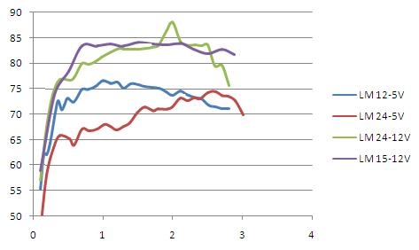
The diagram below shows the efficiency of the converter depending on the current consumed from the converter. We have shown the efficiency for 4 different variants.

As you can see from the diagram, the efficiency of the converter is not a constant value and it can be seen here that the highest efficiency of this converter is at 15 V input voltage and 12 V output voltage, and the lowest at 24 V input voltage and 5 V output voltage.
It can also be seen that the efficiency also varies with the load on the inverter.
As you can see, the efficiency of this converter does not exceed 85%, where many sellers give even greater value in their descriptions.
The graph shows that for the input voltage of 24 V and output voltage of 12 V at approx. 2 A, the efficiency is approx. 88% - I did not notice it during the measurements, but I would consider this value as an error when reading the value from the artificial load display or an error when entering the value to Excel - it only came out when creating the chart.
It can also be seen from the measurements that it is not always possible to load the converter with 3 A and expect that it will hold the voltage at the output.
I also tested the converter temperature for the configuration where the efficiency was the worst - 24 V / 5 V. With a consumption of 2.5 A in this configuration, the converter temperature after 30 minutes was approx. 48 ° C.
Below is a link to the description of a converter based on the same circuit, but with built-in voltage measurement on the input and output sides.
https://www.elektroda.pl/rtvforum/topic3420290.html#16964656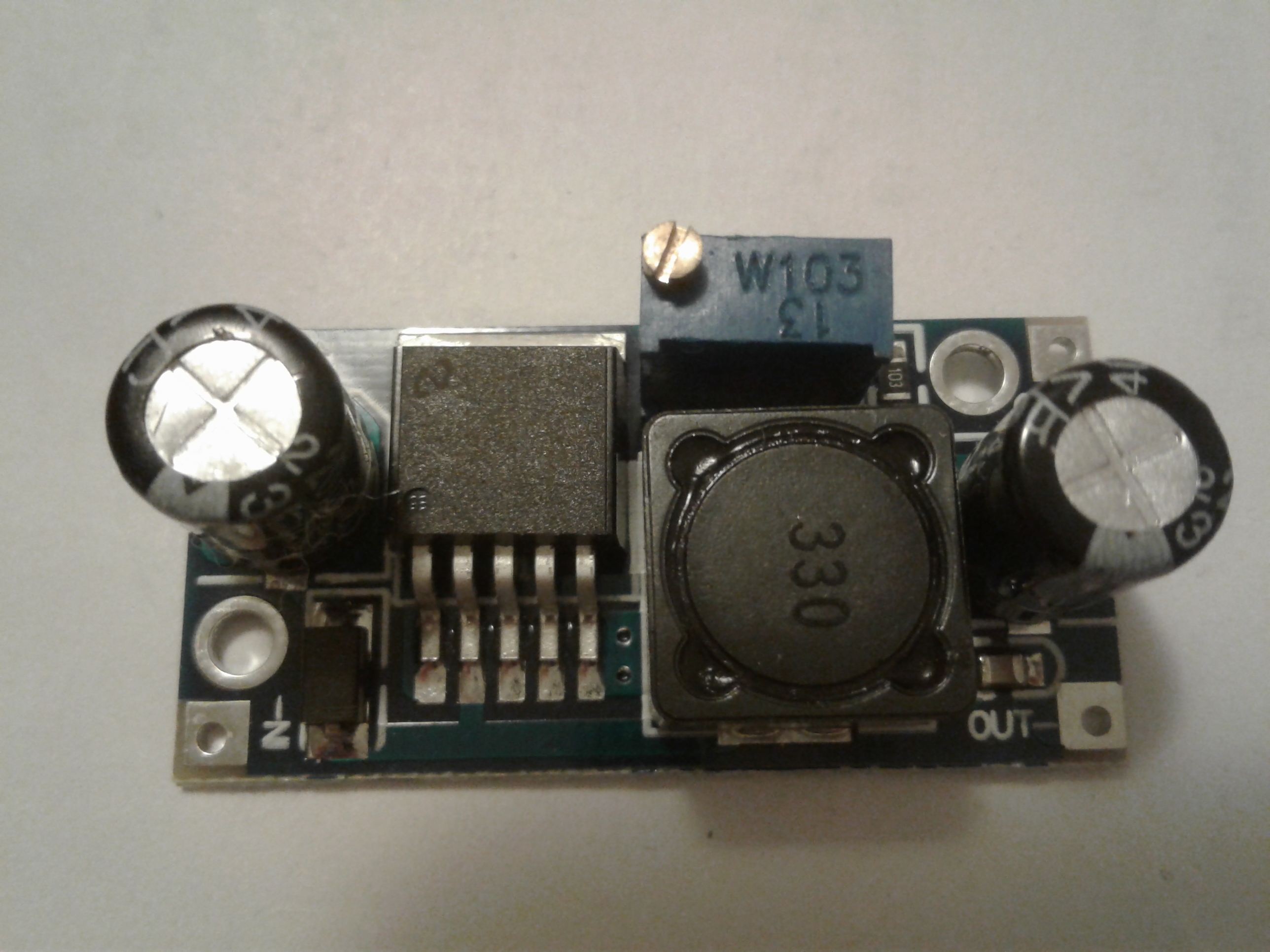
Comments
Good job. The parameters will definitely be useful because the device is really popular. And as with the quality of the components and the ability of the inverter to work continuously. I would like... [Read more]
The question is, is it the original LM National ... :) [Read more]
Good job. The only thing missing is the oscillograms under various loads, unfortunately I experienced that this converter is terribly messy at the output and with sensitive systems you need to take care... [Read more]
Do not reverse connect the wires (plus and minus) because the LM2596S explodes. :) [Read more]
For me, this converter has been working for half a year 24/7 in the 17V to 12V configuration. Loaded about 1-1.5A. No problems so far. [Read more]
@lukiiiii: What voltage is at the output of the damaged converter with the LM2596 chip? Has anyone "managed" to burn this chip so that Uout ? Uin; if so, under what circumstances? The post by @ grala1... [Read more]
I have built 3 power supplies on the LM2596-5 and they run for 2 years 24/7 without any problems. The systems consume about 1.5A and the power supply is 12V. In addition, the systems (along with the rest... [Read more]
All wise books "tell" what happens when the circuit works properly and as intended. There is no one that says something about how a broken system behaves, because it cannot be defined. Answering the... [Read more]
Agree that this cannot be read in books. Sometimes, however, a practitioner who has burned several (teen) systems, or even a manufacturer's representative can tell a lot. Once, in the second of these... [Read more]
So you can see how much electricity can flow temporarily. That's why I mentioned the example above. Though I've only burned three so far. [Read more]
I didn't measure it because I was a bit shocked. probably 0 or Uin. [Read more]
Hello How to achieve these 2.8kA? :P 28V and 2.5A Vin after a while Vin = Vout and pufff after the circuit, is it "a lot of Amps"? Is no load ?? best regards [Read more]