Hello.
Below I present to you a description of a cheap two-channel rectangular signal generator with adjustable filling.


Prices in China start from about $ 1.7 with shipping, in Poland from about PLN 29 with shipping.
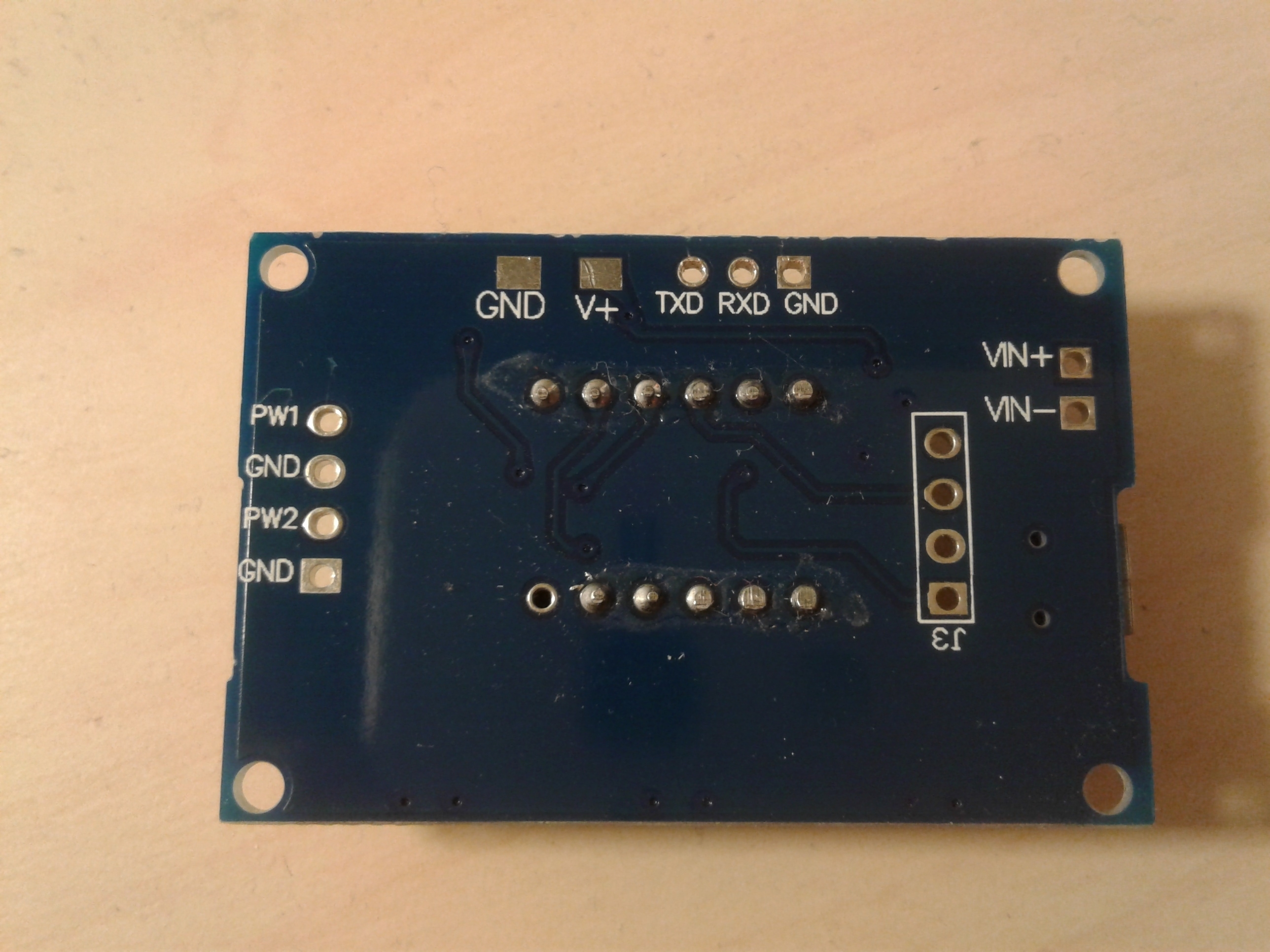
The system is sold as a ready-made set, but you would have to solder the goldpin pins to be able to use it without any problems.
The generator has a 3-digit, seven-segment display, thanks to which you can set both the frequency from 1Hz to 150kHzm and the duty cycle from 0-100% using three buttons ("SET", "UP", "DOWN").
The generator can be powered in two ways - by means of a cable with a micro USB type B plug with voltage of 5V or by means of pins on the board described as VIN +, VIN-. According to the manufacturer's information, the module can be powered with a voltage from 5 to 30VDC, but on the board we can find the HT7150 stabilizer, where, according to the documentation, its maximum input voltage is 24V, so I do not advise you to power the VIN + and VIN- pins with a higher voltage, as this may damage the system. The generator's maximum output current is 30mA.
The manufacturer states that the accuracy is +/- 2% and it actually agrees - it can be seen that the higher the frequency, the greater the error, but it does not exceed the declared value.
The amplitude at the output is 5V, regardless of whether the module is powered from 5V or 24V.
Most likely, this generator is based on some kind of microcontroller. There is an integrated circuit in the SOP20 housing under the display.
Both generator channels work simultaneously. The frequency and pitch of both channels are set using the three buttons as follows.
A short press of the "SET" button causes the display in turn:
- "FR1" - frequency at the PW1 output,
- "dU1" - percentage of the waveform filling at the PW1 output,
- 'FR2 "- frequency at the PW2 output,
- "dU2" - percentage of the waveform filling at the PW2 output.
After selecting one of the above, the selected option will flash three times and display the current value of the selected parameter, which you can change using
using the "UP" and "DOWN" buttons.
When we are at the "FR1" or "FR2" option, each long press of the "SET" button and release it gives us the possibility to choose three frequency ranges:
- XXX: 1Hz - 999Hz - possible change every 1Hz
- XX.X: 0.1 kHz - 99.9 kHz - possible change every 0.1 kHz
- XXX: 1kHz - 150kHz - possible 1kHz change
The reality, however, is different. The first and third ranges work without any problems according to the manufacturer's description. Problems occur with the second range for both channels.
00.1 to 00.9 gives a waveform from 1 to 9Hz where it should generate a waveform in the range 0.1 to 0.9kHz in 0.1kHz steps.
01.0-01.5 all the time generating 1kHz.
01.6-02.5 generates 2kHz all the time.
02.6-03.5 all the time generate 3kHz.
03.6-04.5 generate 4kHz all the time.
04.6-05.5 generates 5kHz all the time.
05.6-06.5 generates 6kHz all the time.
06.6-07.5 all the time generate 7kHz.
7/6-08.5 generate 8kHz all the time.
On 08.6-09.5 all the time is 9kHz.
09.6-10.9 all the time generate 10kHz.
11.0-11.9 generates 11kHz all the time.
12.0-12.9 produces 12kHz all the time.
13.0-13.9 generates 13kHz all the time.
And so on up to 99.9 - the resolution every 0.1kHz declared by the manufacturer does not work, most likely it is the fault of the program in the microcontroller.
The adjustment of the degree of filling the signal works correctly with a resolution of 1% in the range from 0 to 100%.
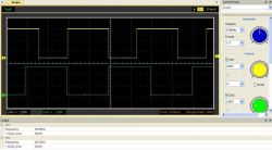
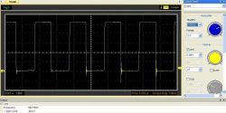
Below are some waveforms from this generator.
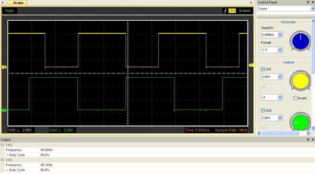
Two channels here at once. 60Hz-60% and 50Hz-50%
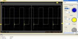
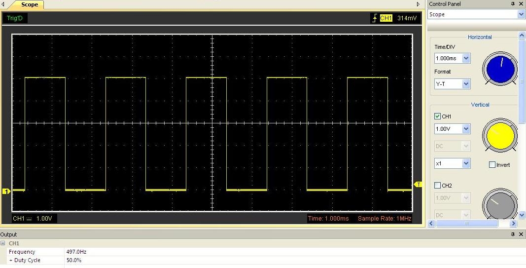
500Hz, 50%
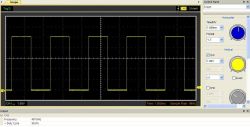
3kHz, 50%
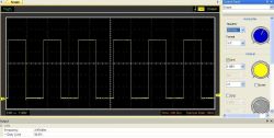
15kHz, 35%

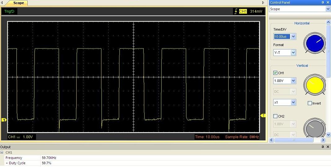
60kHz, 60%
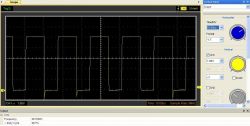
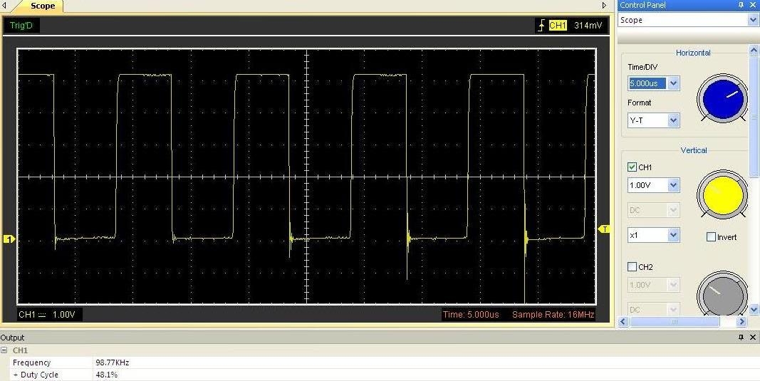
100kHz, 50%
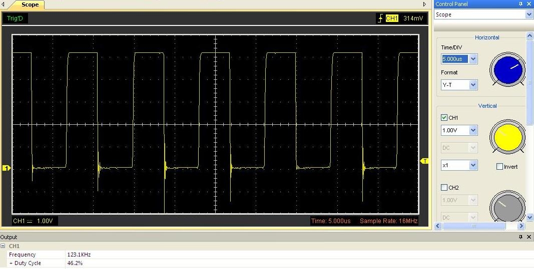
125kHz, 50%
150kHz, 50%
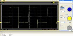
Above 1kHz the generated signal starts to be distorted, which can be seen in the above waveforms. Both channels are affected by this problem.
Finally, a curiosity.
The described generator has the ability to change the frequency and fill the signal for both channels via UART. The GND, RXD, TXD outputs above the display are used for this. It is enough to connect it to a processor or computer, e.g. via the FT232 chip and you can start having fun.
Below are the settings for communication via UART:
Bits per second: 9600
Data bits: 8
Parity: None
Stop bits: 1
Flow control: None
Commands to operate the module via UART:
S1FXXXT - setting the frequency of channel 1 (001 - 999Hz)
S2FXXXT - setting the frequency of channel 1 (001 - 999Hz)
S1FXX.XT - channel 1 frequency setting (00.1 - 99.9kHz)
S2FXX.XT - setting the frequency of channel 1 (00.1 - 99.9kHz)
S1FX.XXT - frequency setting of channel 1 (1 - 150kHz)
S2FX.XXT - setting the frequency of channel 1 (1 - 150kHz)
S1DXXXT - channel 1 duty cycle (001 - 100%)
S2DXXXT - channel 2 duty cycle (001 - 100%)
Example:
First channel frequency 15kHz with 50% duty cycle - we send commands:
S1F15.0T
S1T050T
If the generator on the display displayed information other than the frequency on the first channel (if it displayed the frequency, it will show the set frequency immediately), it will react by displaying the word "FR1", then it will show the set frequency, and after sending the second command, it will display "dU1" , then it will show the desired fill.
Sometimes the generator can return FAIL - it is a reaction to a communication error.
When controlling the generator via UART, the commands should be written in uppercase.
Dimensions: 44 x 29 x 9mm.
I think that despite the flaws that were found in the tested generator during the preparation of this article, it is worth the price and can be recommended.
Below is a link to the description of another, cheaper generator based on the NE555 integrated circuit, where it is also possible to adjust both the waveform frequency and the duty cycle.
https://www.elektroda.pl/rtvforum/topic3422907.html#16981516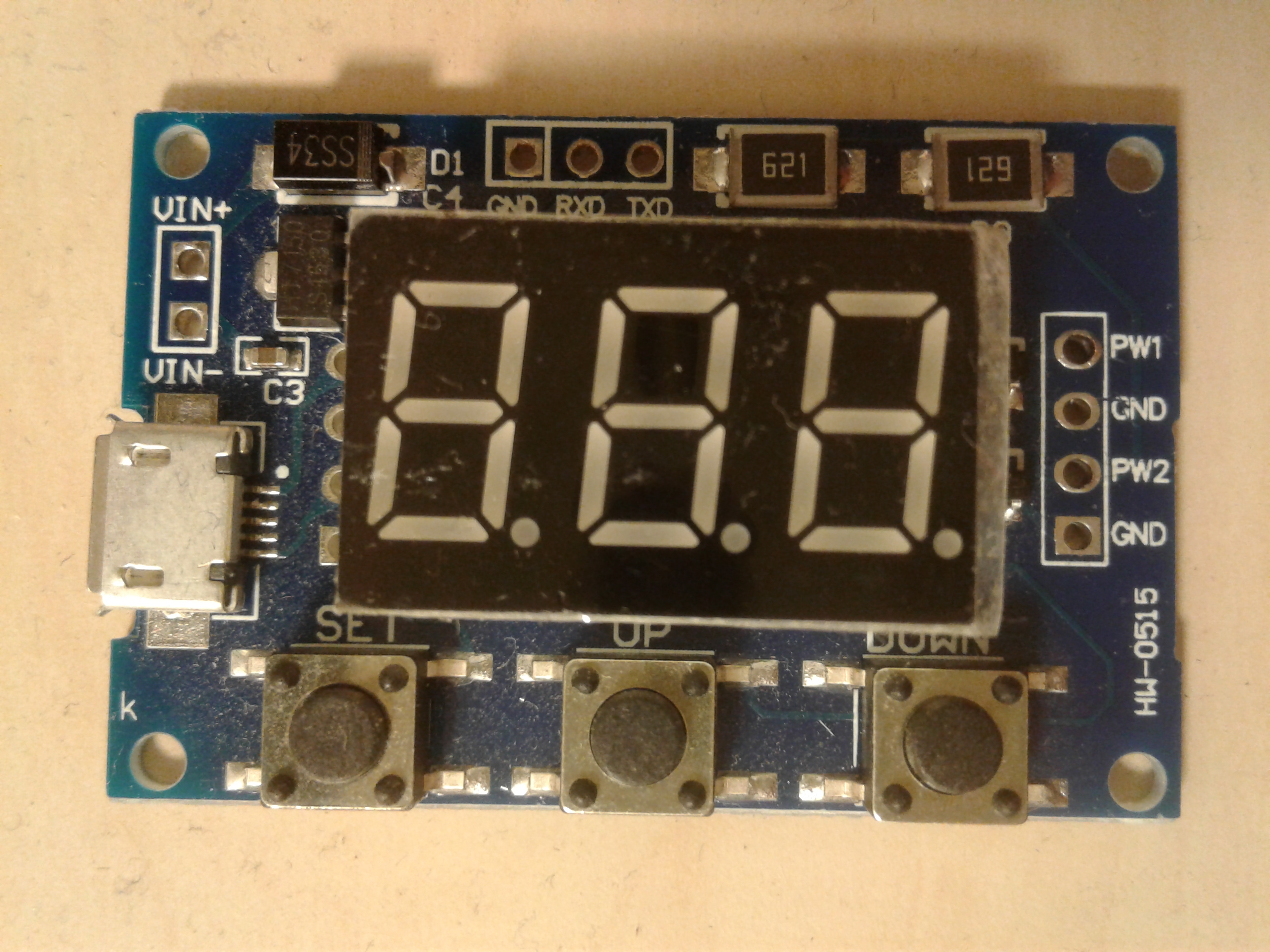


Comments
What password should be entered in the aliexpress search engine to find this generator. Very nice gadget, I would order a few, but can't find it. [Read more]
Please enter "2 Channel PWM Generator Pulse Frequency" you will find what you are looking for :) [Read more]
With which program / snap-in were the uploaded waveforms collected? [Read more]
Hantek 6022. [Read more]
After turning the power off and on again, it adopts some default settings or does it remember the settings? Does it start generating immediately after switching on? [Read more]
It generates immediately, remembers previous settings. It also remembers the setting on which it was turned off - if on FU1, it will be displayed after turning on the power. [Read more]
Have you checked this problem of the second range on other copies of this module? Somehow I can not believe that such an otherwise interesting and useful system was released. [Read more]
I only have one, so I don't know about the others. For me, this problem occurs in exactly the same way on both channels. As it is in other copies, I will not say anything. [Read more]
My friend @ grala1 I admire your inquisitiveness. I was interested in this topic because I would like to make a rectangular generator with frequency change and fill with reasonable parameters and at... [Read more]
@ grala1 It is no coincidence that the ringing op amps on this oscilloscope are. Because it rings on every frequency. This is what it looks like. Some 5V uC will not ring on the pin (it will not go below... [Read more]
Hello, after reading this post, i purchased this generator. it works perfectly well, but I have a question, is it possible to interfere with the system so that the frequency can be lower than 1Hz, e.g.... [Read more]
And how is the steepness of the waveform increase? For example at 1kHz. [Read more]
I already have this layout. Works properly on both channels. Remembers frequency and fill settings when power is turned off. Both slopes are pretty in the whole range. [Read more]