Construction description
The tester was created to learn how to draw patterns in Eagle and learn the basics of microprocessor programming. In addition, it is small in size. I used SMD components for the first time.
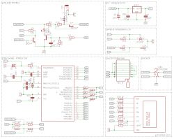
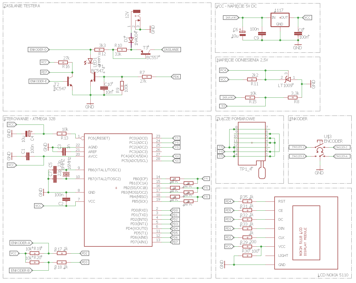
Scheme:
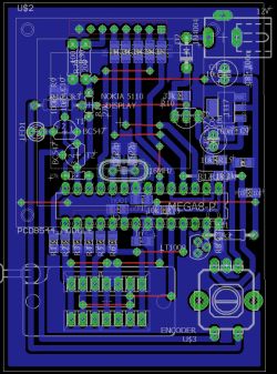
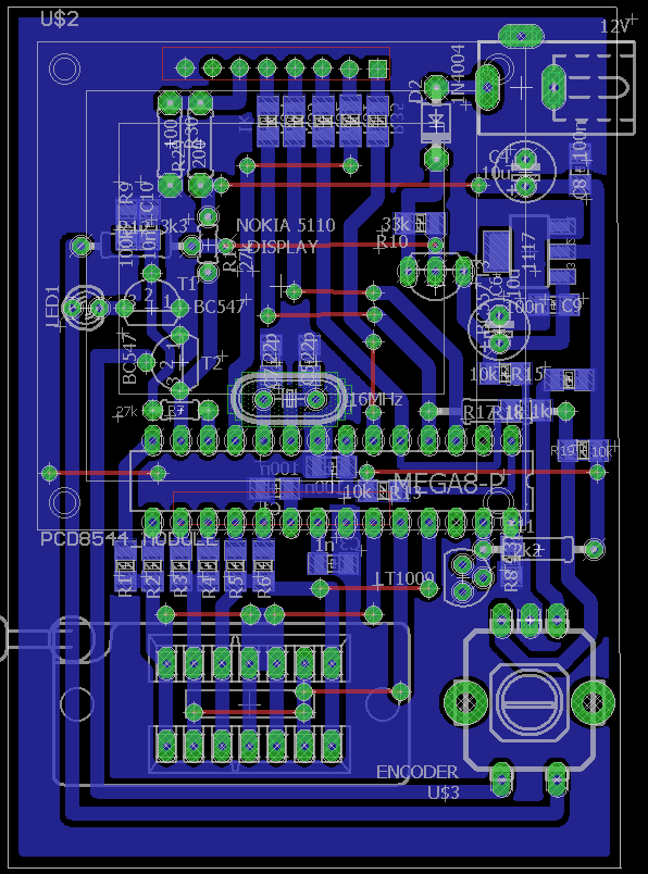
PCB view from EAGLE:
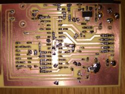
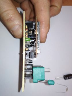
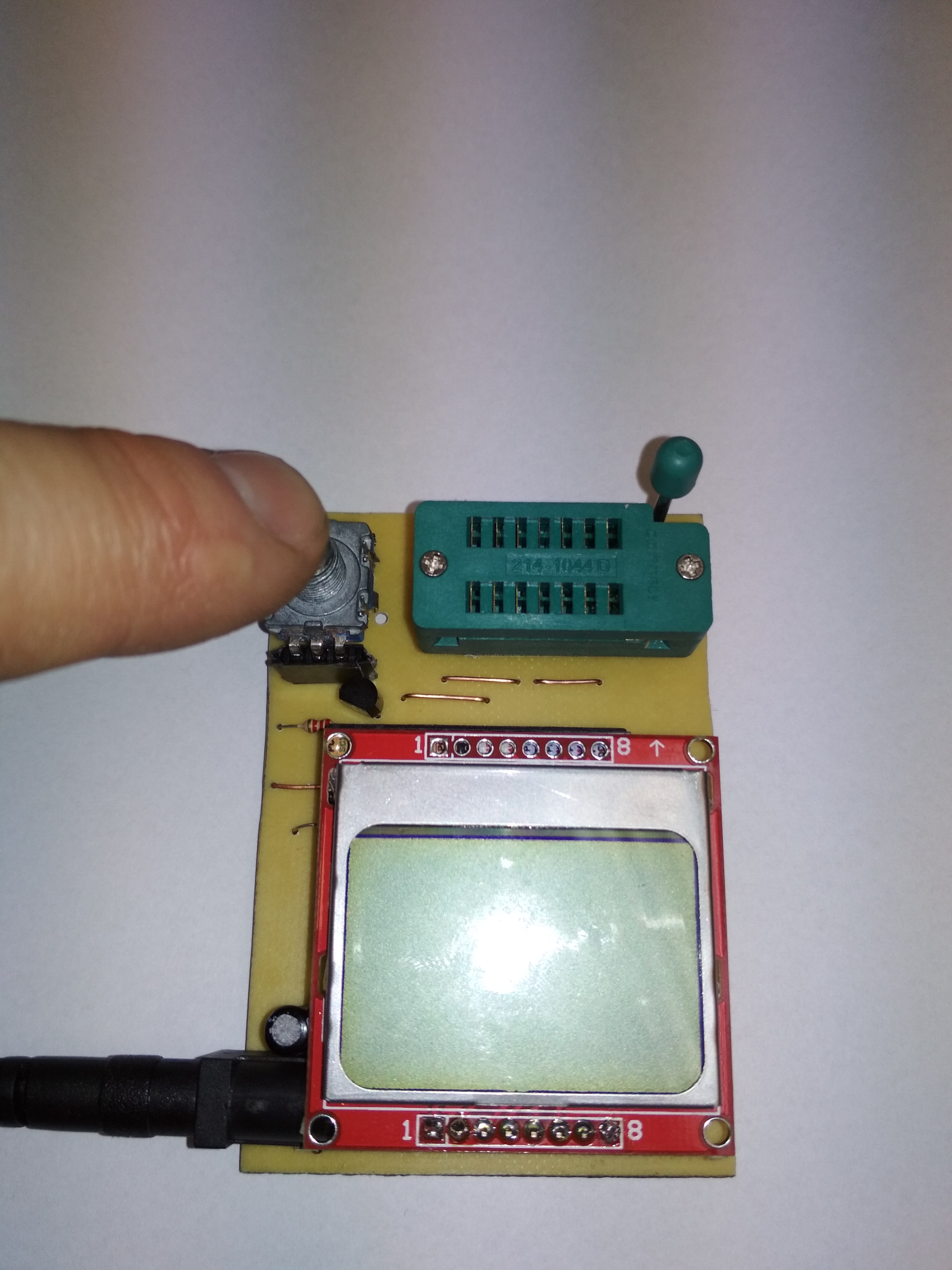
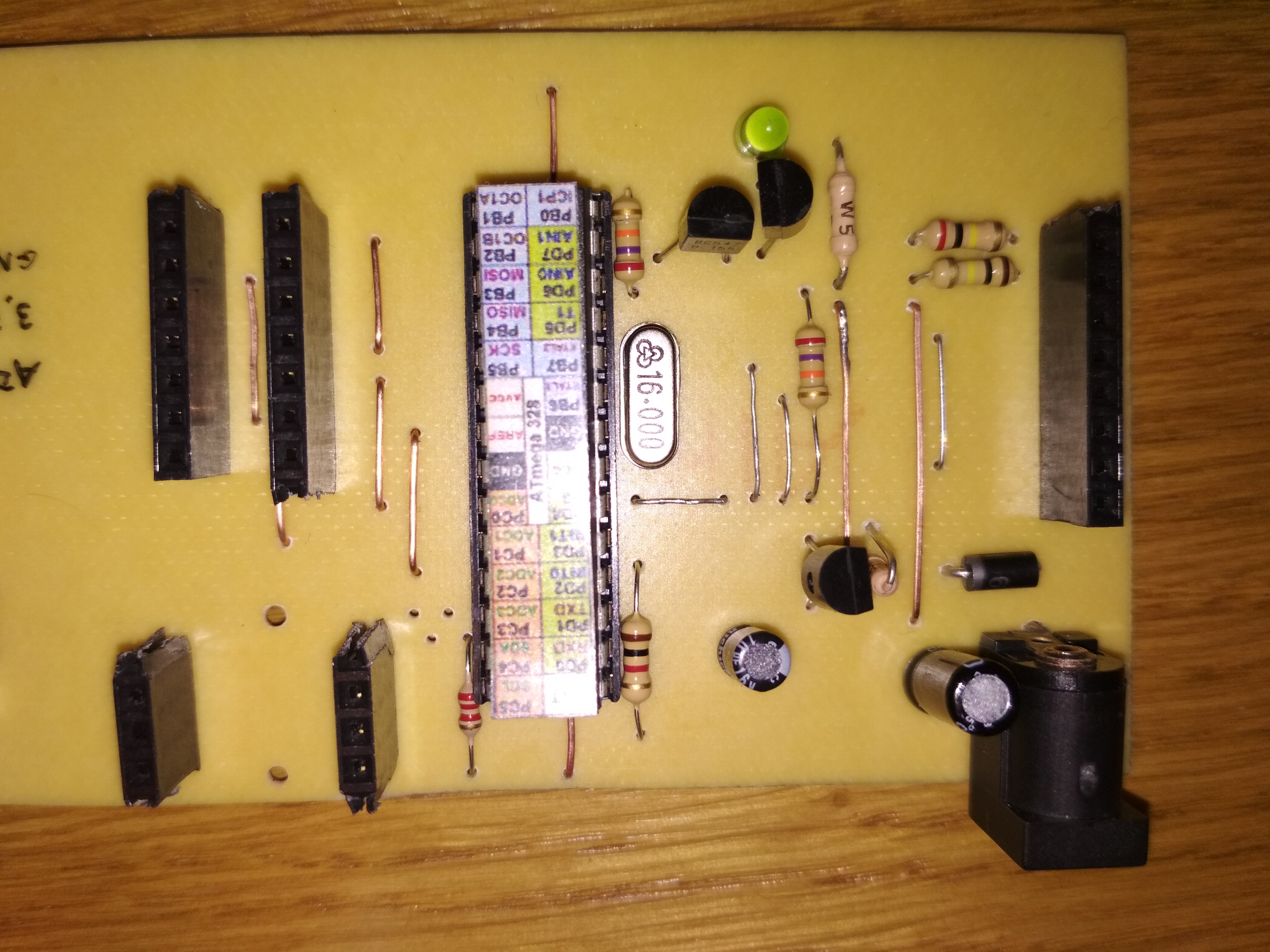
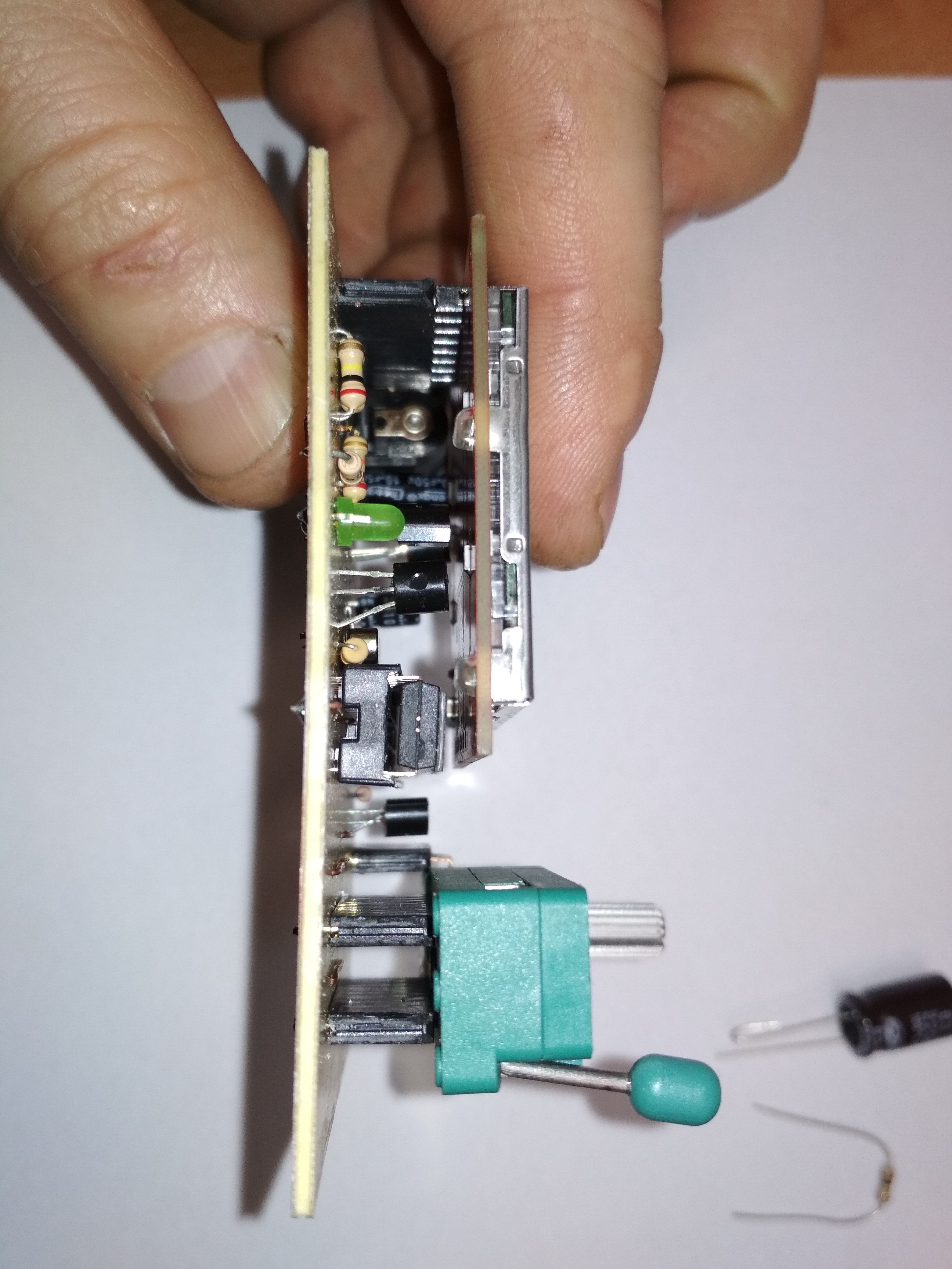
Here are the pictures of the finished structure:


To facilitate the exchange of the ZIF14 processor and socket, they were placed in the sockets.
In addition, the ZIF socket and the encoder should be above the LCD to simplify assembly of the whole in the housing.
The whole structure was made as described on the pages:
Link
Link
The housing of the tester and possible attachments extending its capabilities remained. In addition, you need to protect the paths with, for example, transparent lacquer. For details, I refer to the links above.
It is a well-known construction of the electrode, a novelty is the use of a display from Nokia 5110/3110.
I used 680om and 470kom measuring resistors with a tolerance of 0.1%.
In the software I also entered the exact value of the reference voltage in mV. TL431 reference voltage with a tolerance of 1%. The reference voltage measurement showed 2491mV. This value has been entered in the microprocessor program.
The construction is not without the drawbacks:
- the LED signaling work is located under the LCD (my conscious decision),
- lack of LCD backlight (I found them unnecessary),
- power supply from the 12V power supply (you can easily convert the whole and use a 9V battery),
- execution leaves much to be improved (especially SMD in February).
Here are some videos showing how the tester works:
Attached in the attachment:
1. A diagram in EAGLE with a drawing of paths.
2. A diagram with a drawing of paths in PDF.
3. Compiled source files of the software version 1.31m.
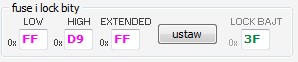
Fusebit settings:

For now, I tested what I have in the drawer and the results come close to measurements by the Chinese ANENG 102 and more familiar and valued UNI-T UT71.
By the way, I can mention that the Chinese meter does not differ by measurements from UNI-T.
Estimate of the constructed structure:
Atmega328 PLN 6
PCB (chemistry for etching) ~ 5 PLN
ZIF14 socket ~ 2 PLN
Nokia5110 display ~ 6 PLN
capacitors, resistors, goldpins ~ 5 PLN
precision resistors 680om, 470kom 0.1% ~ 3 PLN
power socket, encoder, stabilizer ~ 4 PLN
-------------------------------------------------- -------
The whole is about PLN 20 (purchases made on Aliexpress).
In the comments, I ask for constructive criticism, information, what should be improved, etc.
If anyone is interested in additional materials, please contact PW.

Comments
It is a pity that the colleague has not yet added the zener diode tester. On the occasion. How are Fuse set? [Read more]
The zener diode tester requires a converter and I did not want to increase the PCB or do a double sided. The more so because for me, this supplement is unnecessary. I check the coffee grounds exactly tomorrow... [Read more]
To what extent will the measurement be? Fmeter will be an addition to this pcb or will there be a new version? I liked this tester but I would prefer a version with frequency measurement. Will the LCD... [Read more]
LCDs from Nokia3110 / 5110 are in 90% spare cases. Frequency measurement can be added by pulling up the small PD4 pod. Measuring range according to opios on the part of the author of the software. And... [Read more]
Is it possible to test thyristors and triacs with this tester? I have a version for atmega8 and lcd 2x16 I tried with different versions of the software but it does not test even though it should as... [Read more]
Some triacs are properly checked. I did not check the thyristors. You would need to review the documentation of the authors and posts of other users who performed the testers using the same sources. In... [Read more]
lukaszd82 and can you reveal where you bought the smd resistors 680Ohm and 470 KOhm 0.1? [Read more]
The pics show that the resistors used are SMD 1%. Resistors with 0.1% tolerance can probably be obtained, but in THD. [Read more]
The 470k and 680 resistors were on the occasion of other purchases to the company and they were lying to me. Exactly from here: Link These are precise SMD resistors. The others are 1% from... [Read more]
Thanks for the information. I will order at a time, and by the way can Colleague share the coffee grounds to the processor? [Read more]
They are already thrown in the first post. It's just a tester. Normally, I would solder 1% but I had 0.1% on the shelf so I soldered it. I have an old tester at 1% and LCD 4x20, it also works not bad,... [Read more]
It would be great to be watching the topic [Read more]
@ lukaszd82 This is an example of how to draw well schemataty, wszystko czytelnie :) . Have you tested these displays longer in this connection method? My point is that I connect the power through... [Read more]
In other applications so powered, they work for 2 years, but nowhere. On Ali there are such displays with the description 3-5v dc. [Read more]
I even have one of the ali, but no resistors, i.e. version at 3.3v. since it works with 10k resistors, I will leave it, and power probably also by the dam resistor. He builds something like that https://www.youtube.com/watch?v=qtws6VSIoYk&list=PLPzPGtYrTsR-1_Cv4n0s0oAG89AQQnZjq&index=3... [Read more]
@lukaszd82 is it possible upload .hex file to Arduino Uno [Read more]
is it possible upload .hex file to Arduino pro mini [Read more]
You have other instructions on arduino ... link link [Read more]
Hello,i made this project ,but when i push encoder module turn on for 2-3second and shown battery .30v and then says (battery is low) then turn off. I change reference voltage pice to lm336-2.5v it happens... [Read more]