Today I would like to introduce you to GPS signal receivers. I will try to do it on the basis of a ready-made module that uses a U-BLOX chip, namely a system called NEO-6 in the "M" version.

I will not describe here how the receiver position measurement works. The NEO6-M module is equipped with a UART TTL interface thanks to which we can communicate with it and receive data using the NMEA-0183 protocol.
NMEA is the National Marine Electronics Association, it is a protocol specification that allows communication between various types of measuring devices and a simple connection of the GPS receiver with other devices.
The NMEA standard sends out independent lines of data, where each line:
- starts with $ sign;
- has a header;
- cannot exceed 80 characters;
- each nada is separated from the next by a comma;
- data in the number format may have fractional values expressed after the dot sign;
- may be ended with a checksum in the form of a two-digit hexadecimal number preceded by an asterisk.
Below I will describe a few lines of data, they will not be all possible in the NMEA protocol, but only those that our NEO-6M receiver sends to us via UART.
GGA - Fix information
Example:
$ GPGGA, 151654.00,5145.11403, N, 01803.73294, E, 1.04,4.86,131.8, M, 38.3, M ,, * 50
GGA - header identifier;
151654.00 - time when the data was received. 15:16:54 UTC time;
5145.11403, N - latitude, 51 ° 45.11403'N;
01803.73294, E - longitude, 18 ° 03.73294'E;
1 - measurement quality;
04 - number of tracked satellites;
4.86 - position accuracy - HDOP;
131.8, M - height above sea level;
38.3M - height of the geoid above the WGS84 ellipsoid;
no data - time since the last DGPS update;
no data - DGPS station ID number;
* 50 - checksum.
As you can see above, we are missing two data. DGPS stands for Differential GPS, it is data sent by ground stations and our receiver does not support it.
The measurement quality can have the following values:
0 - no item or item with a very large error;
1 - position determined on the basis of GPS;
2 - position determined with the participation of DGPS;
3 - PPS position;
4 - Real Time Cinematic;
5 - Float RTK;
6 - estimated;
7 - manual impet mode;
8 - simulation mode.
The position accuracy, more precisely the horizontal position accuracy of the HDOP, determines the estimated position accuracy. It is generally assumed that a HDOP value lower than 6 is sufficient to make a decision, for example, to turn at an intersection.
GSA - Overall Satellite data
Example:
$ GPGSA, A, 3,16,26,21,31 ,,,,,,,,, 5.98,4.86,3.49 * 00
GSA - header;
A - automatic position selection, another option here is M - manual;
3 - 3D position, other possibilities 1 - no fixed position, 2 - 2D position, 3 - 3D position;
16,26,21,31 ,,,,,,,, - numbers of satellites used to calculate the position, space for data from 12 satellites;
5.98 - DOP - precision of the designated position;
4.86 - HDOP - horizontal precision;
3.49 - VDOP - vertical precision;
* 00 - checksum.
GSV - Detailed Satellite data
Example:
$ GPGSV, 3.1, 12.02, 11, 045, 05, 24, 069, 13, 09.02, 357, 12, 03, 126, * 7A
GSV - header;
3 - the number of lines the application should read in order to obtain complete data on all satellites. We are limited to 80 characters here, because of you this information is presented on three lines;
1 - current line number - see above;
12 - number of currently visible satellites;
02 - satellite identifier - PRN;
11 - the elevation of the satellite above the equator - expressed in degrees;
045 - satellite azimuth - expressed in degrees;
no data - SNR - received signal level;
successive values define subsequent satellites - we can have a maximum of 4 satellites described in one line;
* 7A - checksum
GLL - Lattitudal / Longitunal data
Example:
$ GPGLL, 5145.11403, N, 01803.73294, E, 151 654.00, A, * 68
GLL - header;
5145.11403, N - latitude 51 ° 45.11403'N;
01803.73294, E - longitude 18 ° 03.73294'E;
151654.00 - position fix time, UTC time;
A - active status, V - inactive;
* 68 - checksum.
RMC - Recommended minimum of data
Example:
$ GPRMC, 151655.00, A, 5145.11396, N, 01803.73254, E, 0.055,, 300418 ,,, A * 79
RMC - header;
151655.00 - position fix time, UTC time;
A - status, A - active, V - inactive:
5145.11396, N - latitude 51 ° 45.11396'N;
01803.73254, E - longitude 18 ° 03.73254'E;
0.555 - object speed in knots;
no data - the angle of the object moving;
300418 - April 30, 2018;
No data - there should be Earth's magnetic variation;
* 79 - check sum.
VTG - Vector track and speed over the Ground
Example:
$ GPVTG ,, T ,, M, 0.055, N, 0.102, K * 20
VTG - header;
lack of data - walking path in degrees - ,, T;
no data - path based on magnetic coordinates in degrees - ,, M;
0.55N - speed in knots;
0.102K - speed in km / h;
* 20 - checksum.
Some data on our finished GPS receiver.
The most important element here is the NEO-6M module which is powered from the RT9193-33 stabilizer, the maximum supply voltage of which is 6VDC, so it is best to use a 5V voltage source. According to the documentation for the NEO-6M, the current consumption is a maximum of 67mA but our receiver uses 60mA before catching the "FIX" and about 50mA after catching the "FIX". On the board we can also find 24C32 eeprom memory and a small battery thanks to which we can use the "warm start" function. According to the documentation, the cold start is 27 seconds and the warm start is 1 second. What does the concept of cold and warm start mean? Cold start means starting a long unused receiver and waiting for the receiver to fix the position, i.e. catching the FIX, while warm start means finding the FIX after a momentary loss of signal or after a momentary power outage. In the case of my receiver, you have to wait about 15 minutes from turning on the power to find the FIX - this time also depends on whether the receiver is inside or outside. The more the receiver sees the "cleaner" sky, the faster it will catch the signal. The rechargeable battery in my receiver is enough for about 60 minutes of power backup.
The NEO-6M module is equipped with interfaces such as UART, SPI and USB. Unfortunately, in this receiver model, the board manufacturer only provides the UART interface, where its logic is at 3.3V, the data provided by this interface is refreshed with a frequency of 1Hz. On the board we also have a goldpin connector where the power supply should be given - VCC, GND, output for the already mentioned UART - TXD, RXD, and the PPS output - pulse per second, i.e. the output on which we receive a signal with a frequency of 1Hz - more precisely, we have the state here high with a duration of 100ms and low status with a duration of 900ms. To this output we have a LED diode connected, which after connecting the power supply shines continuously and after catching the FIX by the receiver it flashes at 1Hz.
To communicate with this version of the receiver you will need a USB-UART adapter, eg FT232.
The dimensions of the receiver are 36x24x12mm, the dimensions of the antenna are 21x6x7mm.
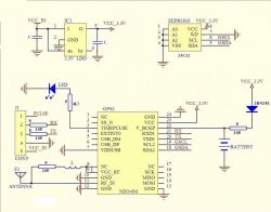
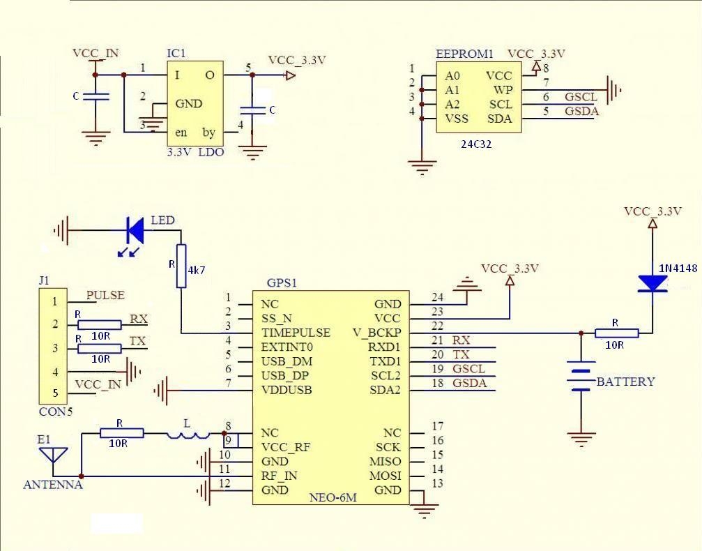
The figure below shows a diagram for this GPS receiver.
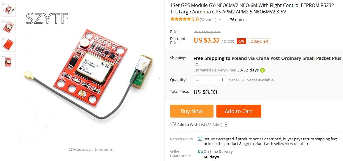
The price of the receiver on Aliexpress starts at $ 3.33 with the antenna included and shipping. On Allegro, you have to spend from PLN 43.65 for an identical GPS receiver with shipping. As you can see, the prices on Aliexpress are quite low, but remember that these NEO modules are not new, they are recycled items.
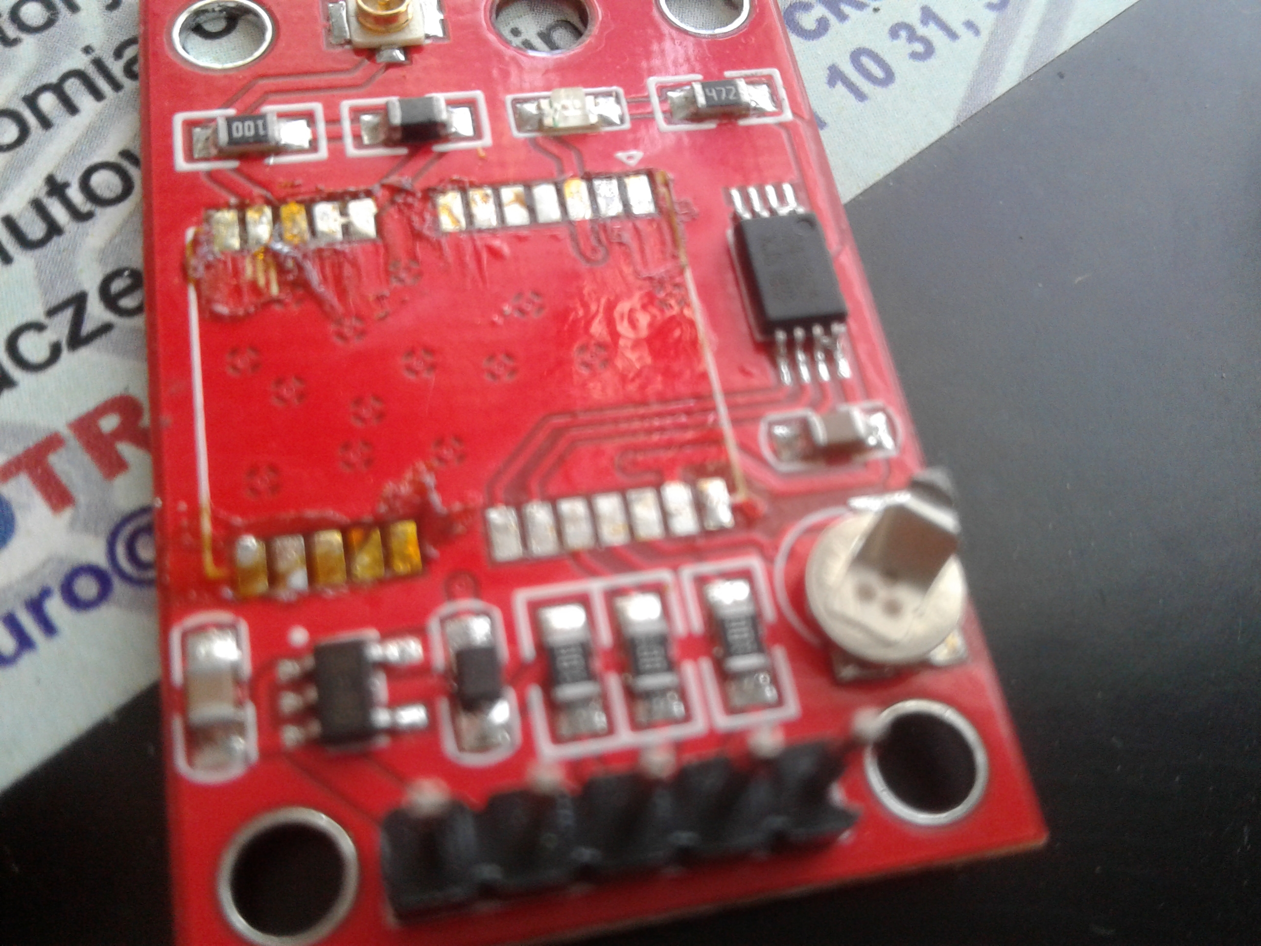
The module I got didn't work at the beginning. After connecting it to a laboratory power supply, the current limit was set to 100mA, the supply voltage dropped due to the activation of the current limit. Increasing the current did not help - it turned out that it is not the receiver that gets that much, but rather a short circuit. I desoldered the NEO module and after connecting the power supply, the current limitation of the power supply was still working. It gave some hope that the module could be functional, and after carefully examining the board, I found two places where there were short circuits. They were on the eeprom memory.
You can see it in the pictures below.

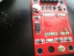
One of them did not matter because 1-2-3-4 legs were tightened, but here 1-2-3-4 legs are tight on the board. The legs 7-8, i.e. on the memory power supply, were also tight. After removing these short circuits, surprisingly, the stabilizer worked - a tough beast. After soldering the NEO module and powering the receiver, the LED finally turned on and it was possible to establish a connection with the receiver.
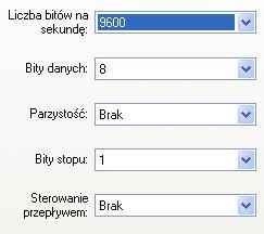
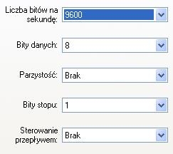
I used FT232 and the HyperTerminal program to communicate with the receiver. Settings for communication in the program below in the photo.
After communicating with the receiver, we get a "frame" of data, which before catching the FIX looks like this:
$ GPGGA, 173745.00 ,,,,, 0.05.99.99 ,,,,,, * 60
$ GPGSA, A, 1,10,29,27,26,16 ,,,,,,,, 99.99.99.99,1.00 * 0D
$ GPGSV, 3,1,12,04,41,180,24,07,08,337,21,08,04,289,18,10,24,173.24 * 7F
$ GPGSV, 3.2,12,13.07.049, 15.10.081.06.16.64.256.10.20.53.103, * 7A
$ GPGSV, 3,3,12,21.71,072.09.26.51,200,19,27,41,291,24,29,15,104.16 * 78
$ GPGLL ,,,,, 173745.00, V, N * 49
$ GPRMC, 173746.00, V ,,,,,,, 300418 ,,, N * 73
$ GPVTG ,,,,,,,,, N * 30
After catching FIX the "frame" looks like this:
$ GPGGA, 173747.00,5145.08762, N, 01803.70069, E, 1.04,12.82,184.1, M, 38.3, M ,, * 68
$ GPGSA, A, 2,10,29,27,26 ,,,,,,,,,, 12.86,12.82,1.00 * 0D
$ GPGSV, 3,1,12,04,41,180,24,07,08,337,22,08,04,289,17,10,24,173.25 * 72
$ GPGSV, 3.2,12,13.07.049, 15.10.081, 16.64.256, 20.53.103, * 7D
$ GPGSV, 3,3,12,21.71,072.08.26.51,200,19,27,41,291,25,29,15,104.17 * 79
$ GPGLL, 5145.08762, N, 01803.70069, E, 173747.00, A, A * 64
$ GPRMC, 173748.00, A, 5145.08837, N, 01803.70165, E, 0.382,, 300418 ,,, A * 77
$ GPVTG ,, T ,, M, 0.382, N, 0.708, K, A * 25
After getting acquainted with the NMEA protocol, we are able to determine the position of our receiver, time and altitude above sea level on the basis of such a frame.
We can enter this data, for example, in Google Maps to find the receiver's position on the map.
At the beginning, I entered the data 51.4508762 18.0370069 which gave a difference in the measurement by about 20 km. At first I thought that maybe it was a damage caused by an earlier short circuit on the PCB or maybe the quality of the system, what to expect for a dozen or so zlotys. The receiver went into the corner and I was waiting for the washerwoman with a new GPS receiver. After a few days, I sat back to this receiver, looked for data on the NMEA protocol and finally noticed where the error was in reading the coordinates from the "frame". At the beginning you have a description of the protocol and the conversion of data to coordinates. Below are some other options for converting coordinates from the "frame".
In the box above, the position is 51 ° 45.08762'N, 18 ° 03.70069'E, UTC time 17:37:47 (19:37:47 CEST), 184.1m above sea level.
51 ° 45.08762N 18 ° 03.70069E
As you can see here, the seconds are written in "decimal" form. You can also enter 51 ° 45'05.3 "N 18 ° 03'42.0" E where the record is already in the form of minutes and seconds. This notation is obtained by multiplying the value of the decimal minutes by the value 60.
0.8762x60 = 5.2572sec?5.3sec
0.70069x60 = 42.0414sec?42.0sec
This data can also be entered in other ways. We can divide the value of minutes by 60.
45.08762: 60 = 0.751460
3.70069: 60 = 0.061678
Then enter: 51.751460N, 18.061678E
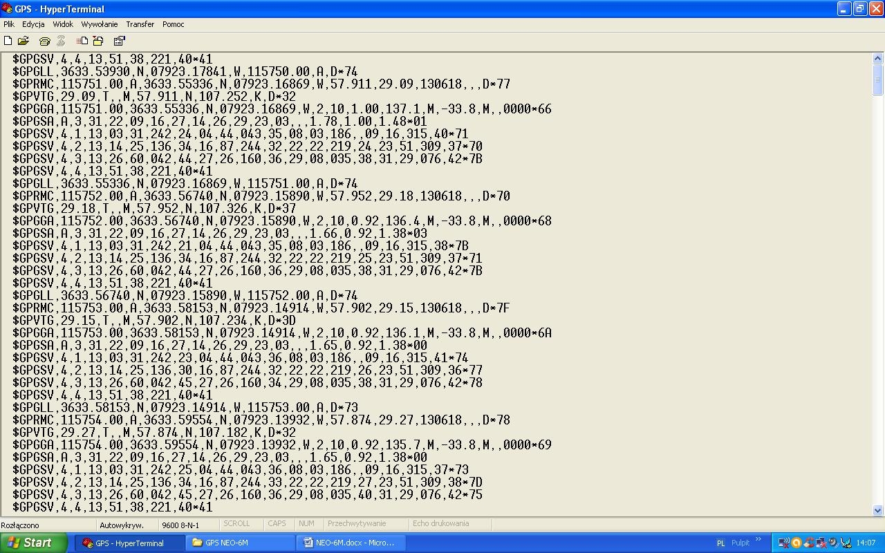
Below is a picture from the HyperTerminal program while using the receiver while driving the car.
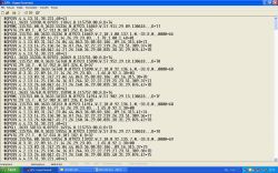
You can find the movement speed here. The speed indicated by the car's counter was 110 km / h. while the GPS receiver showed 107 km / h. From my experience, I can write that the speed shown by the GPS is always lower than the car's odometer - usually it is approx. 5 km / h, of course it depends on the speed of the car.
Honestly, I thought that reading data from this receiver would be much more difficult and as you can see it is quite simple.
This module can lose the signal if, for example, we have it placed at home. When viewing the data received via UART, you can see that it can lose the signal for several seconds or longer (it depends of course how well it sees the sky) and then find the signal again. I have not noticed similar symptoms when the module works "in the open air". When using it in the car, I also did not notice the loss of the signal when the receiver was placed on the dashboard. I think that with a larger antenna this problem will occur less frequently and the time of catching FIX after the first turn on should decrease.
This module can be used to build e.g. a position recorder by combining such a module with a microcontroller or by adding a SIM module to this set, you can build a GPS tracker. In Google you can find examples of building a GPS tracker using this receiver, SIM module and Arduino.
In the attachment documentation for the NEO-6 module.

Comments
Interesting description, is it "real" u-blox or "compatible" with u-blox? The 1Hz PPS output allows you to obtain a reference frequency cheaply. I used the Waveshare NEO-7M module with an external antenna... [Read more]
TechEkspert, this 1pps can also be of different quality and is not always suitable for reference. Although the price of the module encourages you to experiment anyway. [Read more]
@mkpl rightly, the reverse experiment and checking the stability of the 1PPS GPS signal would be interesting, e.g. with a thermostated quartz generator or, for example, if someone has access to the rubidium... [Read more]
Such a little information from me. Maybe you already know, but you haven't written, and if you don't know, you'll find out. After entering the coordinates into Google Maps, you won't get... [Read more]
It is enough to multiply the seconds by 0.6, as the author wrote (or added later) More info here: https://support.google.com/maps/answer/18539?hl=pl&co=GENIE.Platform%3DDesktop The link "www.google.pl/maps/place/%s+%s"... [Read more]
Were you able to activate and deactivate specific types of messages in this module? https://gis.stackexchange.com/questions/198846/enabling-disabling-nmea-sentences-on-u-blox-gps-receiver [Read more]
@ atek000 apparently you didn't read the text thoroughly. It explains how to convert. In Google Maps, you can enter coordinates in 3 ways: 51 ° 45.08762'N, 18 ° 03.70069'E 51 ° 45'05.3... [Read more]
@ grala1 I know mine is not u-blox because in the description it had "compatible with u-blox" and there is no manufacturer's logo on the module. What is 1PPS? Perhaps it would be possible to examine... [Read more]
Once I bought the cheapest of the cheapest modules from a Chinese, 99% had already been soldered before. In addition, they had traces of corrosion from the flux used for the discharge. I recommend sigrok... [Read more]
I haven't met the original ones on Ali yet, and I have bought some from various sellers for testing. Therefore, at auctions in their titles there is no word uBlox but NEO something there (ot Aliexpress... [Read more]
But for what and for what? The 1PPS signal is not created as a direct reference signal, but only as information about the passage of another second. The signal typically for a commercial receiver has... [Read more]
@Sas_AS Well, with regard to what is a good question, if we do not have the right model, it is difficult to investigate something, comparing two or three GPS receivers, perhaps, would give information... [Read more]
Generally, you do not have to go far as uBlox has such modules on offer, for example LEA-M8T / NEO-M8T https://www.u-blox.com/sites/default/files/NEO-LEA-M8T-FW3_DataSheet_%28UBX-15025193%29.pdf Anyway,... [Read more]
@TechEkspert as for the test of differences between receivers, I agree in terms of the reference standard. @tplewa for frequency standards for the amateur laboratory. Rather, I wanted to instill... [Read more]
@Sas_AS Oh, my friend probably didn't understand me. I am glad that my friend raised a lot of interesting matters here and it has a huge educational advantage, etc. My entry was supposed to be... [Read more]
@tplewa We understood each other ;) Just wanted to clarify so that somebody doesn't choke on a rubidium generator without checking with another generator which has 1PPS synchronized signal with... [Read more]