.
Hello my dears .
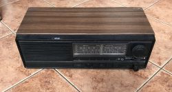
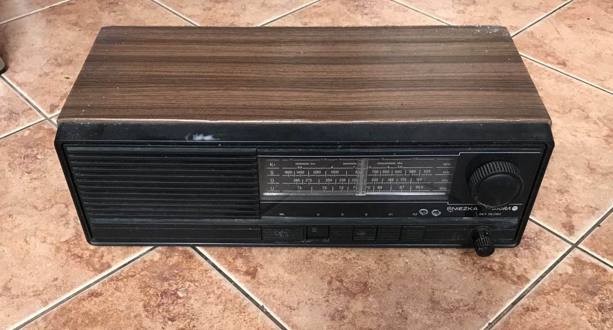
In this short topic I would like to present the interior of an old Polish radio receiver UNITRA Sniezka R-207. The receiver presented here I rescued from electro-waste - I don't know how someone could throw it away, it is a good piece of Polish electronics history. It was manufactured in the 1980s/90s. After refreshing (and tuning) it can play nicely again.
I will also post its schematic diagram and component catalogue notes in the topic.
Interior of UNITRA Snowball R-207 .
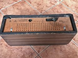
The radio case is made of veneered chipboard. Only the front is plastic:
.
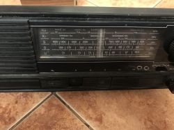
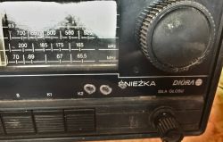
The front shows the proud inscription "Snow Diora" and we can see the ranges on which we can receive. Tuning is of course done mechanically, with a big knob. Next to it is the volume potentiometer:
.
The radio has 5 ranges, which are selected using the buttons - K2 and K1 (short wave), S (medium), D (long), U (UKF), the wave ranges shown in the photo above.
.
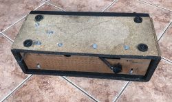
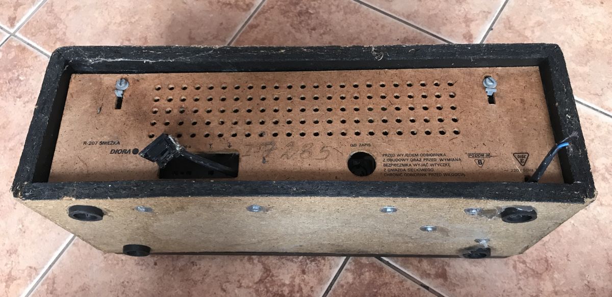
On the back we have a fibreboard on which there is also information about the specific model (R207):
.
.
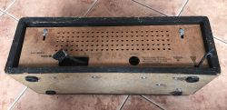
I received the radio in the condition as shown in the pictures. The 220V power cable must have been cut off some time ago, because the copper wires are heavily rusted. In addition, someone must have fiddled something with the speaker connector and added it so that it only holds loosely on the wires:
.
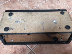
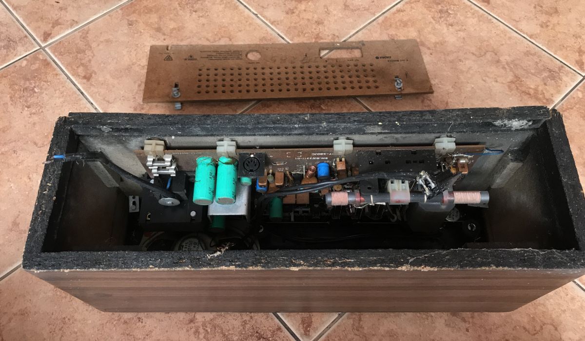
The hex screws on the bottom hold the single laminate plate with the electronics inside the case. Two screws on the fibreboard at the back hold this plate - it can be easily removed:
.
Rear plate removed:

.
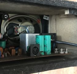
The electrolytic capacitors, which may have to be replaced, are glaringly visible.
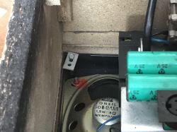
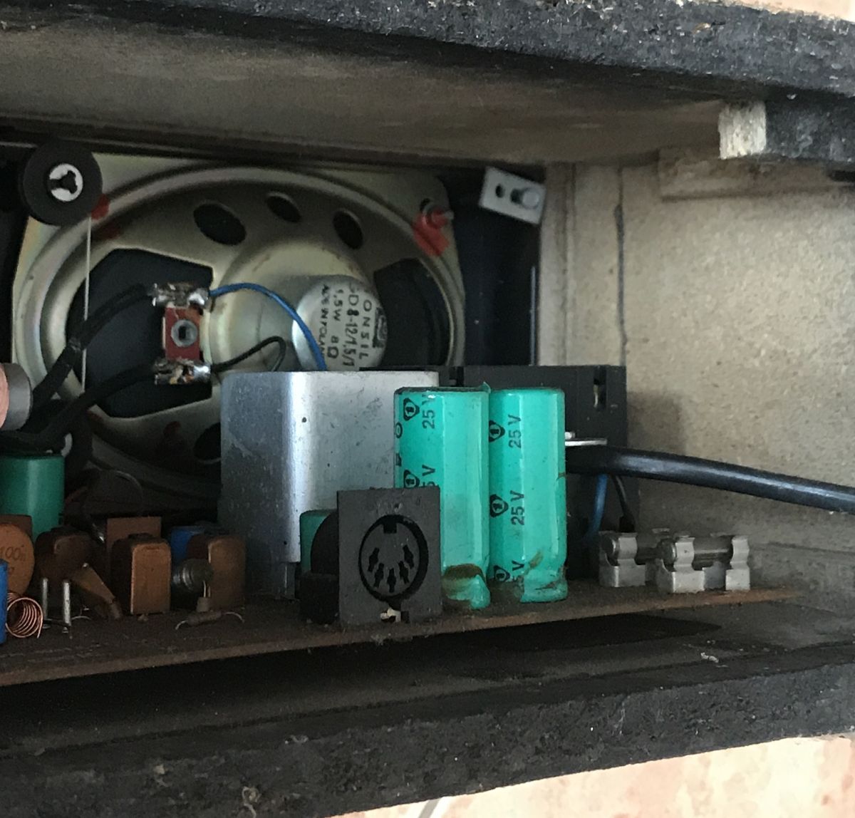
You can already start looking at the interior - you can see that there is a single Tonsil 8Ω speaker inside:
.
Above you can see the distinctive GM545 socket.
.
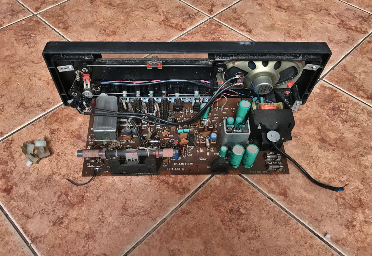
The electronics PCB is fixed to the front and slides out of the case along with the front:
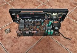
.
In the photo above you can also see the cable and rollers and the tuning carriage - a mechanical arrangement.
In addition, we can see that someone has rummaged around here before - an additional connector is plugged directly into the speaker.
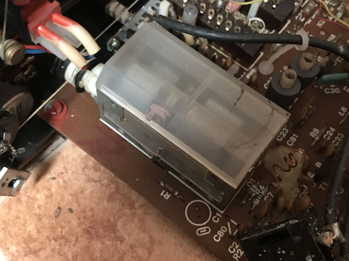
The plastic parts holding the laminate look like this up close:
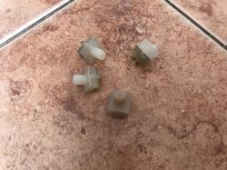
.
There is a distinctive ferrite antenna on the board:
.
Adjustable capacitor used to select the frequency on which to receive:
Potentiometer from the volume knob (manufactured by Telpod, 47kΩ, wired into the loudspeaker amplifier circuit):
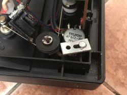
.
It may have to be replaced or cleaned - wear and tear on the potentiometer (its carbon tracks) can manifest as crackling in the speakers, among other things.
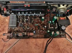
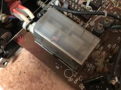
On the board you can see the fuses and the mains transformer:
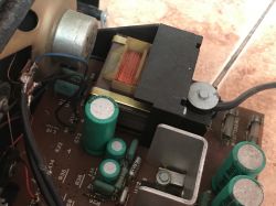
.
This mains transformer is probably a TS-6/21.
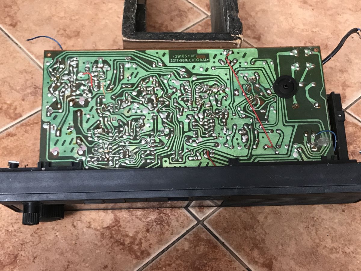
PCB from underneath:
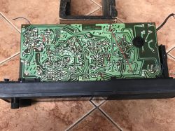
.
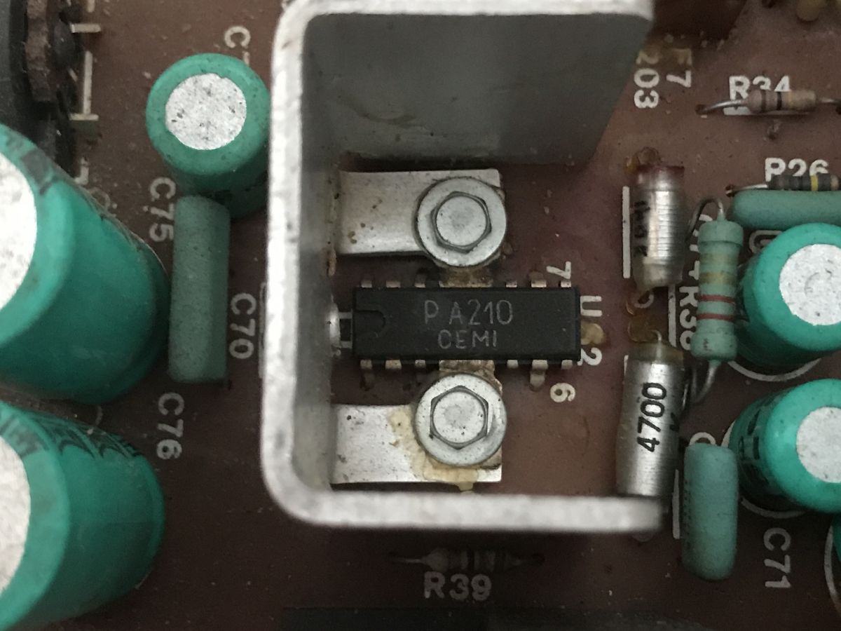
There are two integrated circuits in the radio. PA210 by CEMI (6W power amplifier):
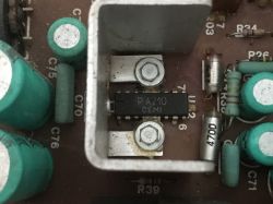
.
UL1211 (also from CEMI), AM/FM intermediate frequency amplifier:
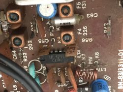
.
Component schematic and datasheet .
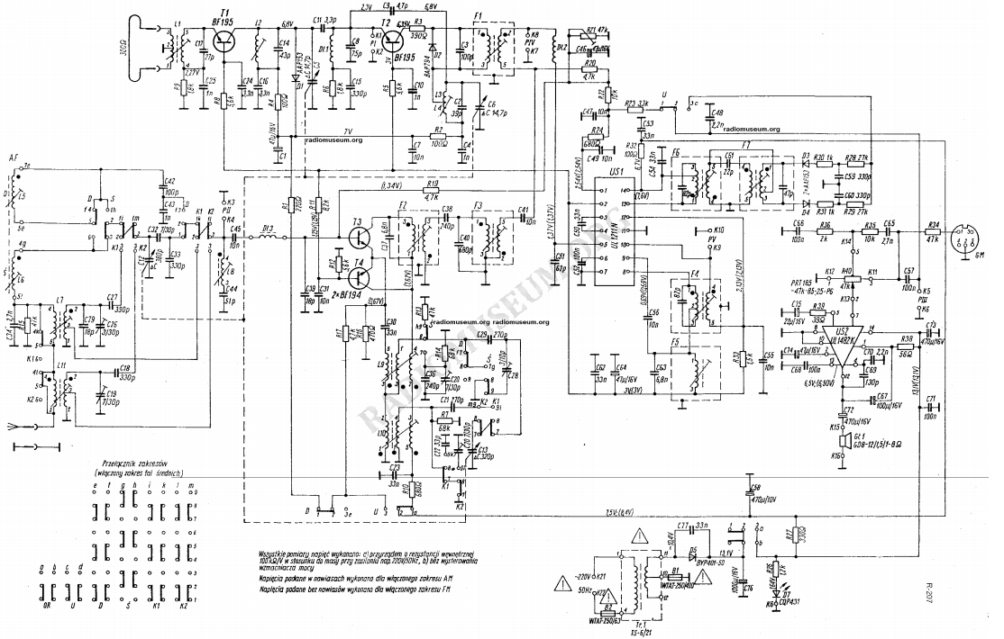
The schematic of this radio can be found in many places on the web, I am also posting it below for the convenience of readers:

The schematic shows the voltages at certain points, which makes fault diagnosis easier.
The power amplifier in this schematic is UL1482 (not UL1481), although in my PCB it is PA210.
Notes of these two ICs:
UL1482.pdf (161.16 kB)You must be logged in to download this attachment. .
UL1211..pdf (378.89 kB)You must be logged in to download this attachment. .
BF195 and BF194 transistors are also used in the radio. Transistor catalogue:
BF194_CEMI...ota.pl.pdf (2.13 MB)You must be logged in to download this attachment. .
An AAP153 germanium diode sits in the head:
AAP153.pdf (161.28 kB)You must be logged in to download this attachment. .
Summary .
I have shown here the interior of an old Polish UNITRA Sniezka R-207 radio receiver. The receiver has not yet been run by me at this point, but perhaps I will get around to it soon. Probably the UKF reception range will have to be tuned as well.
In the meantime, I invite you to discuss - do you have any experience with this type of radio, maybe some stories or anecdotes? .


Comments
Cool that you are saving something for posterity. How much of it went into the rubbish. Of the rescued ones I have: Diore U2 pcs 2, Jovite 1, well that's what I use every day. https://obrazki.elektroda.pl/6132845100_1601129796_thumb.jpg... [Read more]
The PA210 is the export equivalent of the UL 1481/1482. They used whatever they happened to wind up in the assembly :P . An external speaker socket added amateurishly and in a rather idiotic way - connecting... [Read more]
You will have room to play with when tuning. The coils have no core but are air coils. You will have to work hard with the compression and stretching of the heterodyne coil (L3/L4). I have a similar... [Read more]
Very doubtful, I have repaired these radios, the capacitors have never failed and these will also be good, at most a slight hum will mean that the At most, a slight hum will mean that a capacitor from... [Read more]
Hello, at one time I played around a bit with tuning the UKF range, the ukf heads from those years are practically the same, I still have a TARABAN 2 radio. Greetings. [Read more]
I was involved in the service for 40 years and you have to admit that there is beauty in simplicity.... [Read more]
Well no, it's not simple at all because the pile of filters makes it quite difficult for an amateur to tune, if there were ceramic filters then yes, and there were back in the day. [Read more]
Hello The heterodyne coil can be rewound with a new one, to which the capacitance of the capacitor is selected to get the desired tuning bandwidth. A frequency indicator with LED display... [Read more]
. I repaired radios for quite a long time in those days, you don't even realise what some people can do to a radio, dislodged and cracked ferrites also happened. . Because ukf is easier to tune due... [Read more]
Hello Of course, you can still connect a voltmeter to the output of the FM demodulator, which makes tuning much easier. One more trick to increase sensitivity, just solder a 12pF ceramic capacitor... [Read more]
The R-207 Snezka and R-208 Sudety radios differ only in the casing - the main PCB is the same. And I would forget the RE-320 Kalenica - the main board is the same as in the R-207 only they added a converter... [Read more]
There is no point in replacing electrolytes if they are not leaking or swollen, as they are virtually indestructible due to their crude construction. ---- I knew a resort in Mielno where they also... [Read more]
. 50 [Read more]
. I did the coil winding from scratch once, when in a tambourine (head as in the jubilat) it turned out that the original winding was not in accordance with the documentation (2.5 coils instead of 3.5).... [Read more]
We've been using this model for years in the kitchen as our primary playing equipment. After tuning, of course. It has worked for many years, a few years ago I dismantled and washed the volume potentiometer... [Read more]
Adds in topic, soldering of 75 Ohm input hot - ground socket [Read more]
. After this modification the equipment will lose value ;) . . This radio has a full-period rectifier in a Graetz bridge circuit, so the capacitors are charged at 100Hz. You probably suggested... [Read more]
With this wooden casing you have gone.... [Read more]
PA210 = TBA810 = MBA810 = UL1481. The UL1482 is a completely different IC, equivalent to the TBA820. [Read more]