 Hello my dear.
 Today we will test and watch another product designed for a smart home, namely the WiFi-controlled WL-SW01_16 16A relay from Tuya. We will check on what elements it is implemented and whether it is possible to upload an alternative firmware to it.
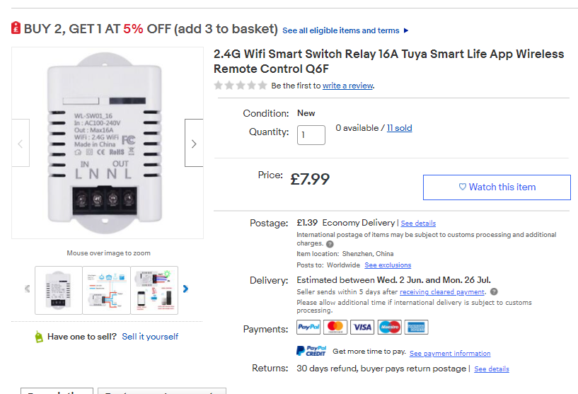
Purchase WL-SW01_16 I found the product on the network under the slogan "16A WiFi Wireless Smart Timer Switch Module DIY Home for Android Apple APP", although it can also be found under its model name (WL-SW01_16). At the time of purchase, it cost about PLN 50, now the price may be different.
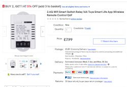
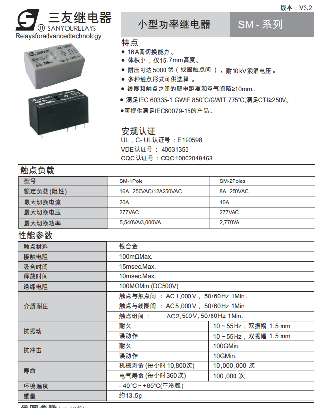
Below I put information graphics from the seller:
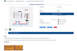
The same relay is also available in our domestic stores (I do not know why the seller calls it 'sonoff', unless he has 'sonoff' all with wifi):
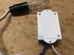
Plastic housing, LED, button and of course the relay inside. You can say that it is such a stronger Sonoff Basic (because BASIC has 10A from what I remember, and this product is here for 16A).
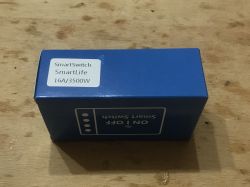
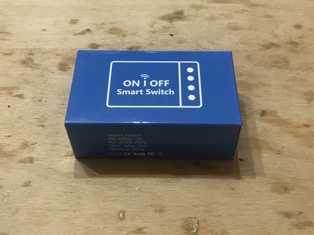
The product came in a blue box:


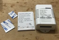
The set includes an instruction and three strips of 9448A 3M double-sided tape:
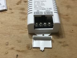
The screw terminal has a removable cover:
 Related Topics
 I have already written a few topics about WiFi products based on ESP (or similar systems). I mainly show interiors there.
I also describe the process of programming such a switch there and using it with the manufacturer's application (Blitzwolf, SmartLife, Tuya, eWeLink) or Tasmota.
I recommend that you familiarize yourself with these topics, I will not repeat all the information several times and as a rule, they apply to all products of this type.
List below:
-
BW-LT30, a WiFi adapter for a light bulb - test, teardown and uploading ESP firmware -
WiFi-controlled electrical socket - BW-SHP8 - commissioning and tests -
Test and interior of the BW-SS3, i.e. the WiFi light switch from Blitzwolf -
PS-16-M WiFi socket / plug and eWeLink / Coolkit application - test and teardown -
SmartLife switch - test, interior and WiFi light switch programming (similar switch, but without RF and description of programming it in Arduino via cables)
-
SC3-01 SmartLife switch and uploading ESP firmware via WIFI (tuya-convert / OTA) (this time programming via WiFi, no need to open the housing, no soldering of cables)
-
WiFi QTouch switch can only be plugged into the L cable - test, interior, diagram (an interesting switch, which is implemented on the thyristor, not on the relay, but also has ESP8285 inside)
-
WiFi SmartLife single-color LED strip dimmer - test, interior, diagram (interesting LED strip driver on MOSFET and WB3S transistor)
Additionally, the topic about Tasmota and the DIY version of the WiFi transmitter:
-
ESP8266 and Tasmota - step-by-step control of the WiFi relay Additionally, I recommend the topic about Home Assistant (which can control a collection of such devices):
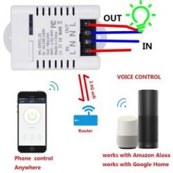
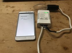
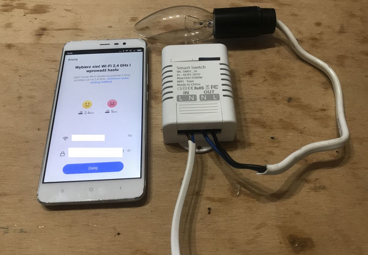
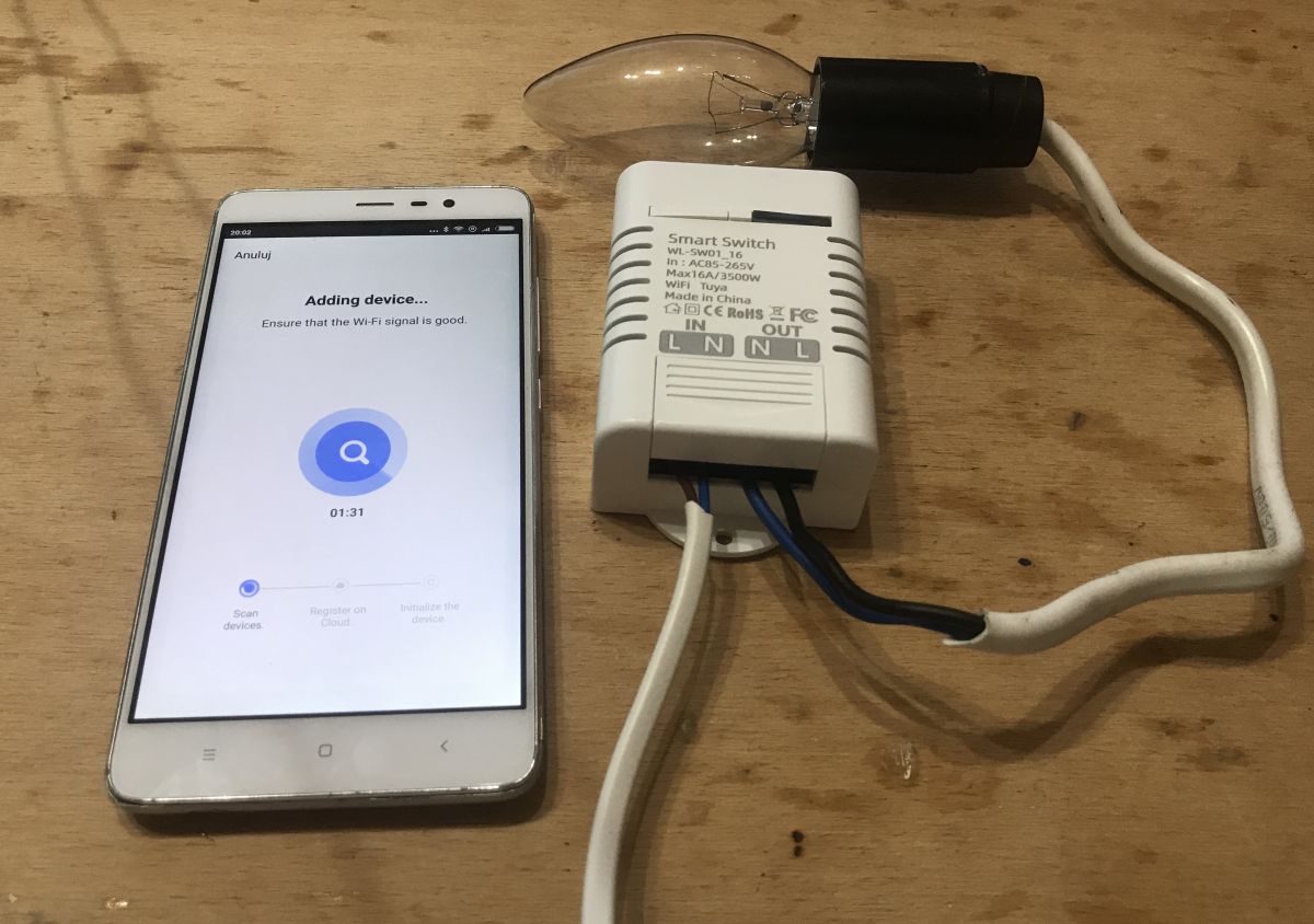
Home Assistant Tutorial - configuration, WiFi, MQTT, Zigbee, Tasmota Pairing with the application, action scenarios Pairing this type of device with the eWeLinkIt / Tuya / Blitzwolf / SmartLife applications has already been described several times, so here I will only give a short description and photo reports. To pair the device, press the button on the housing so that the LED starts flashing and then automatic pairing from the application starts. Pairing takes place via our local WiFi network (we must have a router), only 2.4GHz is supported and of course in the application we must enter our SSID and password.


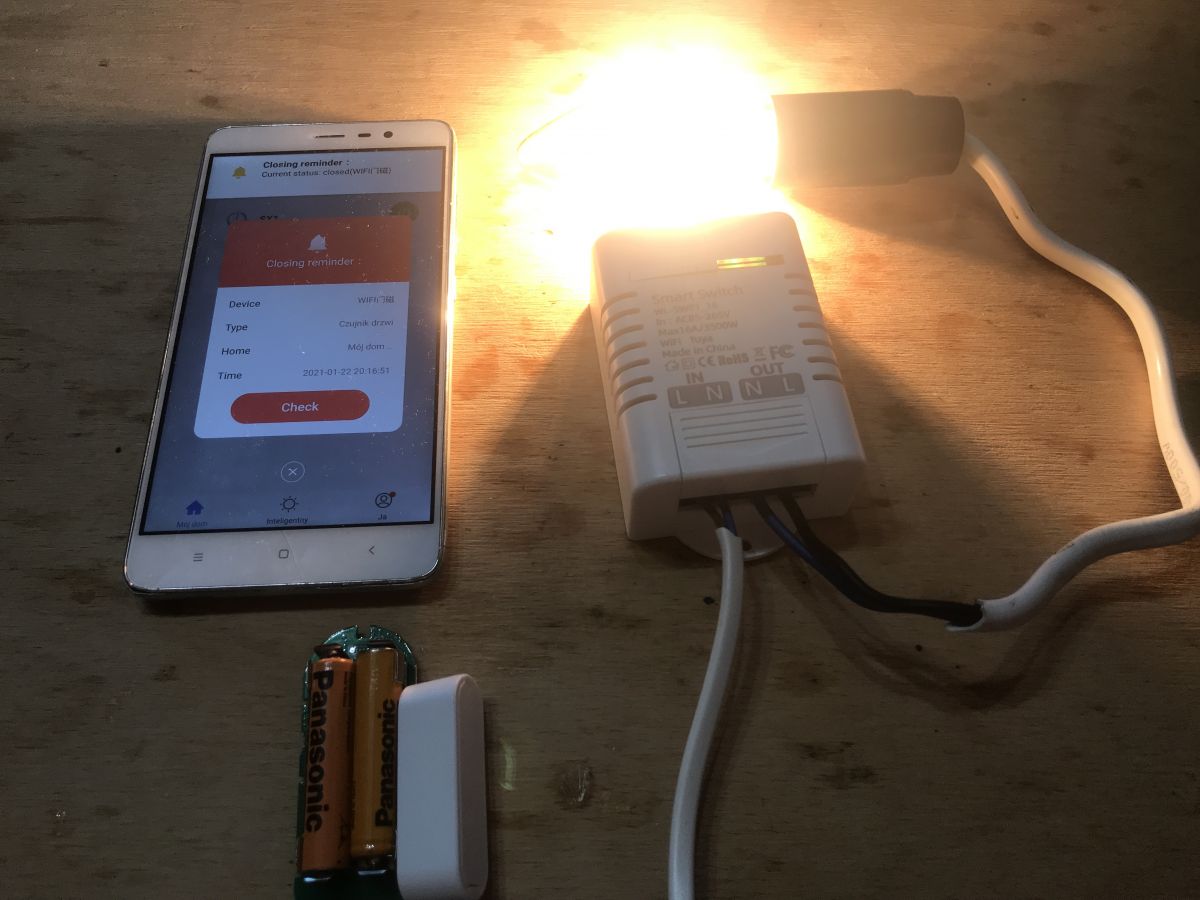
Of course, you can also do scenarios and automations in these applications, for example, trigger a relay using a door opening sensor, as in the pictures below:

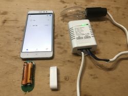
The topic about the door opening sensor used for the demonstration from the photos above can be found here:
https://www.elektroda.pl/rtvforum/topic3771510.html What else does the Tuyi app for WL-SW01_16 offer? We have standard options here, as for all devices, for example:
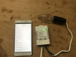
- history of the relay state change:
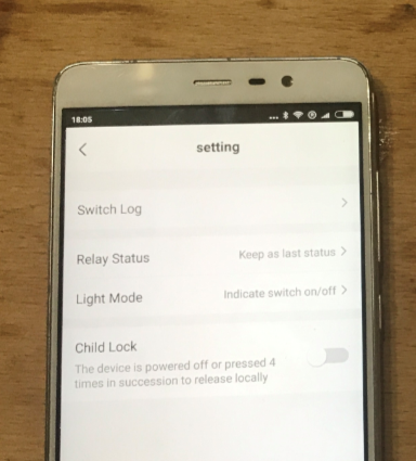
- the ability to set how the relay behaves after switching on after a power failure (does it remember the last status or reset it to a predetermined one):
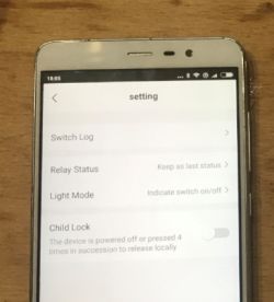
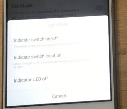
- child lock (child lock; locks the device until the button on the housing is pressed four times)
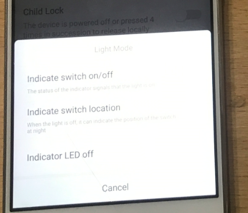
- the ability to change the way the LED works on the relay (whether it is compatible with the status of the relay, or reversed - standby - or always off):
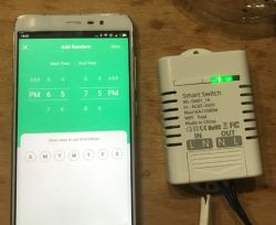
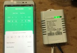
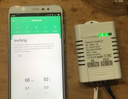
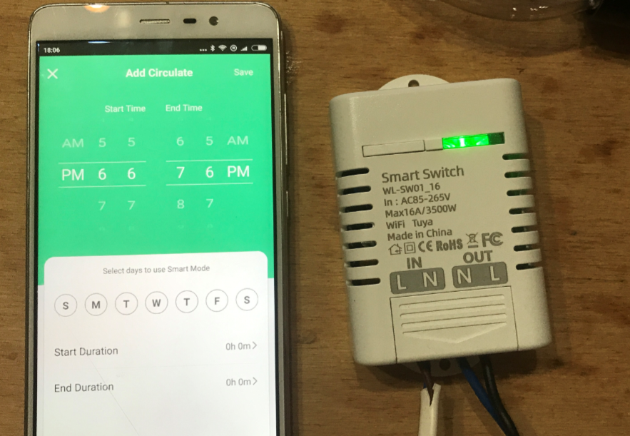
- and of course the calendar / sleep / automations (here as 'Schedule'):
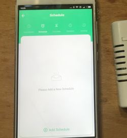
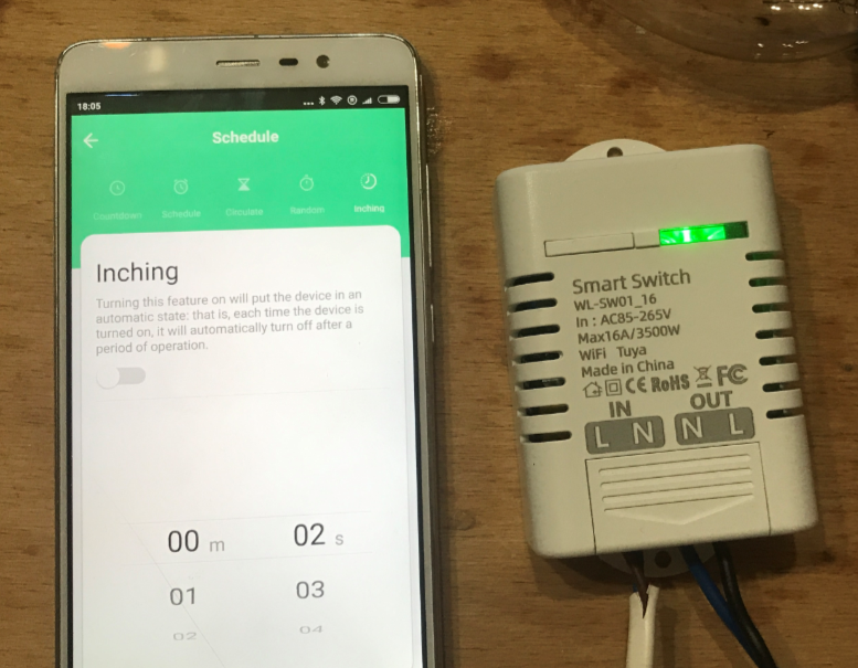
- there is even an automatic extinguishing after turning on after a certain time (described as 'Inching'), which can be useful, for example, for lighting on the stairs:
 Interior WL-SW01_16
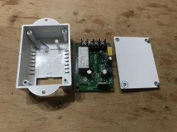
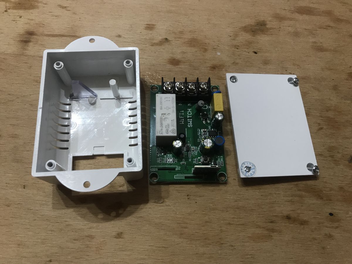
 Now the most interesting, that is, remove the casing. You need to unscrew four screws (one is under the sticker):
Then you can remove the plate:
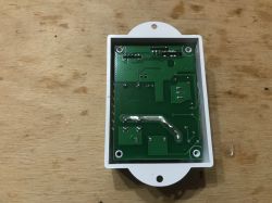
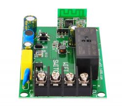
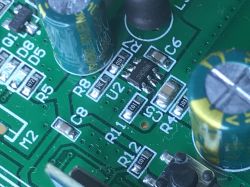
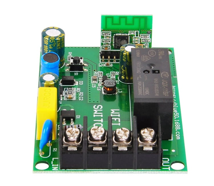
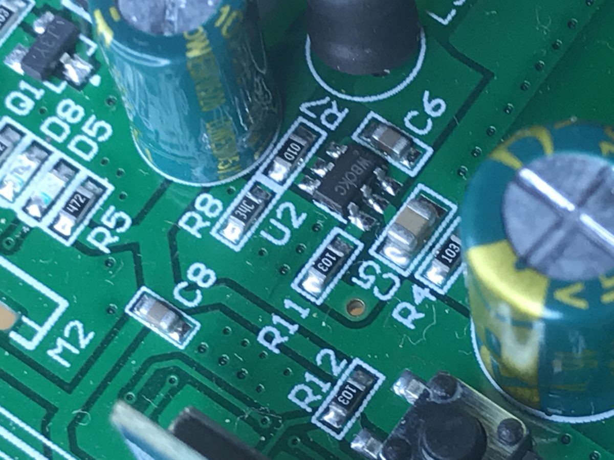
PCB:
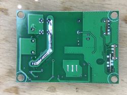
It is interesting that there are places for 3 WiFi modules on the board (of course only one of them is mounted, not all 3 at once) and they are even signed M1, M2, M3. As you can see, the manufacturer was cautious and probably this board is also compatible with WB2S and maybe even with TYWE2S or similar?
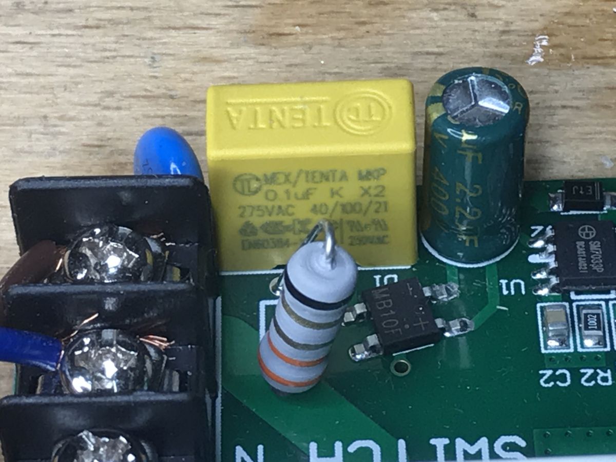
Let's analyze the layout in turn. First there is a varistor (overvoltage protection) and a fuse resistor:
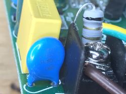
A bit further the X2 class MKP 0.1uF capacitor (anti-interference protection, still on the AC line):

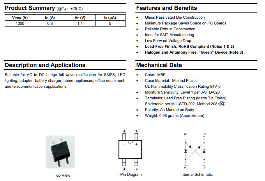
Then we have the MB10F rectifier bridge:
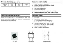
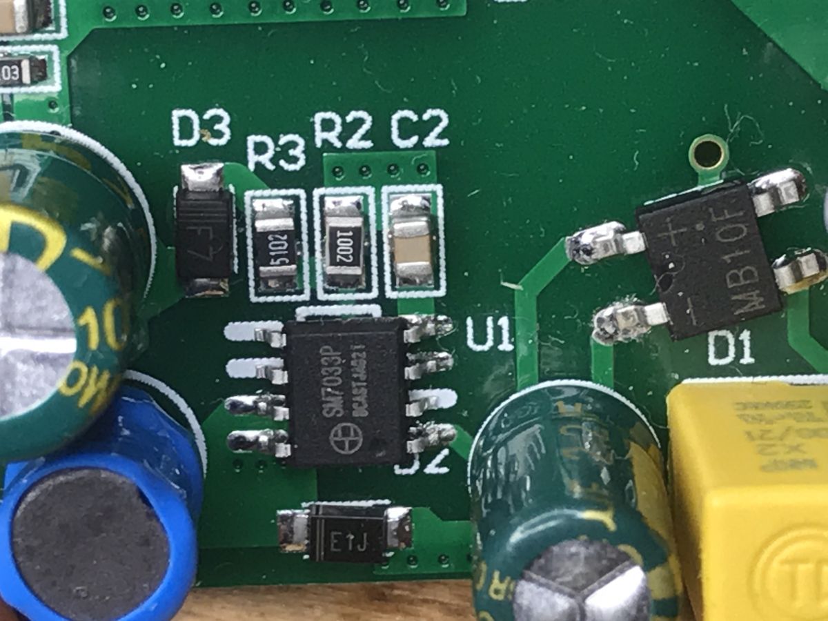
Then there is the SM7033P:
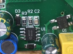
This chip acts as a power supply. It provides 12V for the rest of the chip. First of all, it is noticeable that there is no transformer. It is not a flyback and there is no galvanic separation. The chip datasheet explains how it works:
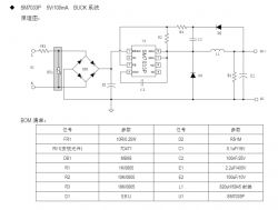
There is 5V in the diagram, but in the layout from the topic, the system provides 12V. It is a buck converter that lowers the mains voltage. The characteristic elements (choke, rectifying diode) can be found on the diagram and on the board. Below I give a general schematic of a buck converter:
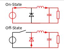
(
image from wikipedia under CC license )
Then we have another agreement signed WBCKC (possibly WBOKC):
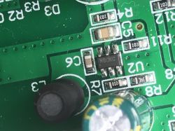
I did not find its catalog note, but the whole circuit (including the choke and capacitor) shows that it is another step down converter. It converts 12V to 3.3V for the heart of the chip (WiFi module).
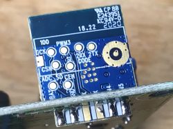
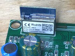
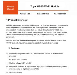
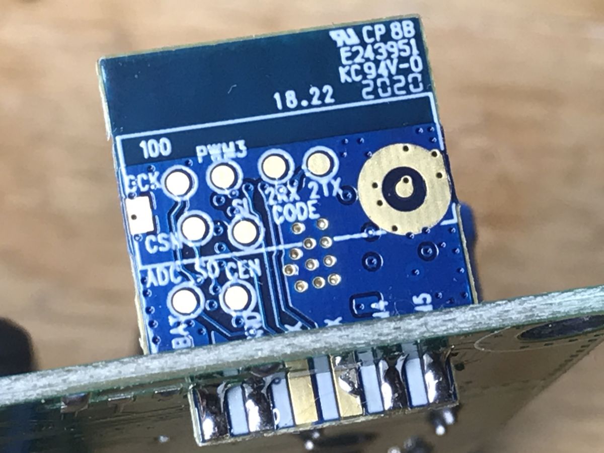
The WiFi module is nothing for ESP. This is WB2S:
(It is worth mentioning that I have already met WB3S in the topic
WiFi SmartLife single-color LED strip dimmer - test, interior, diagram )
The module from Tuya implemented on the 32-bit BK7231D.
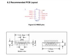
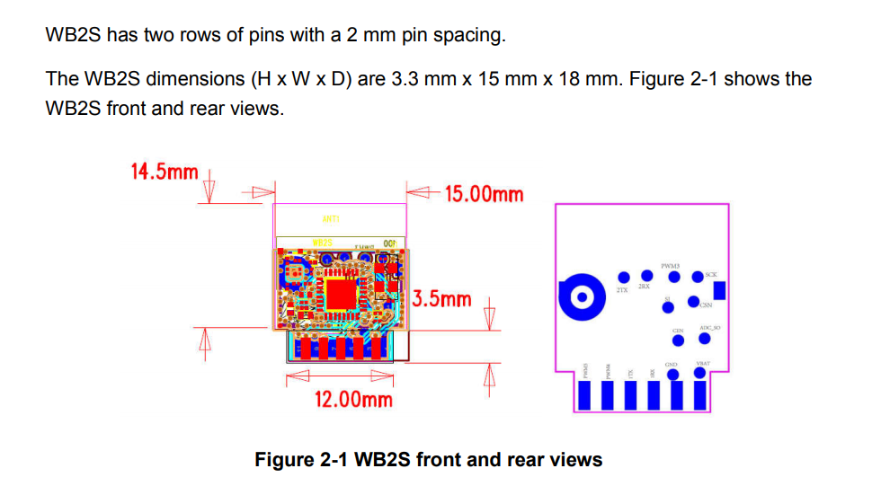
Dimensions:
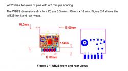
Pinout:
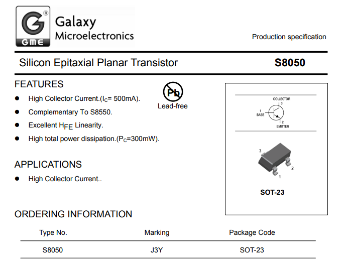
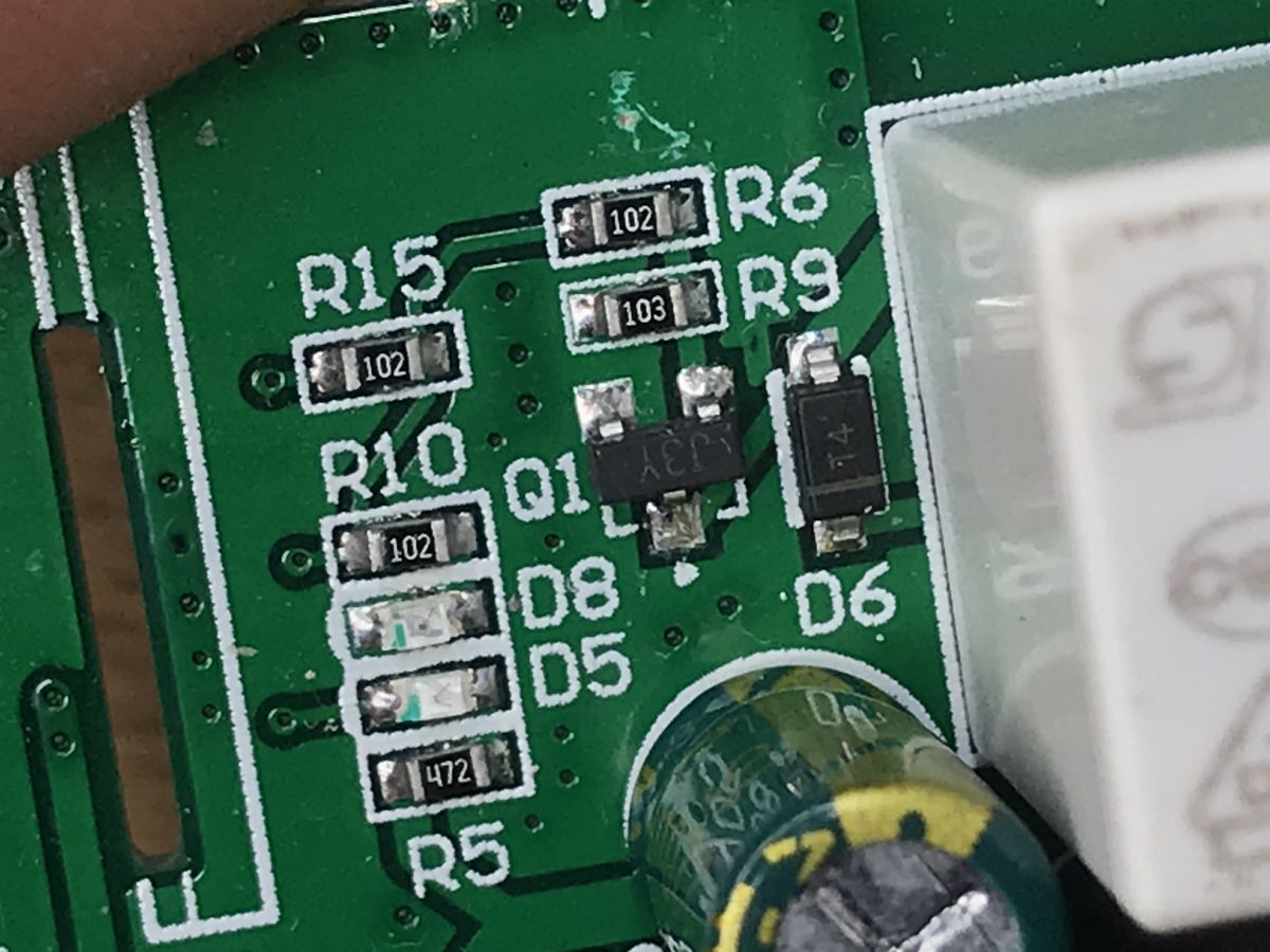
Next to it is a transistor and a button:
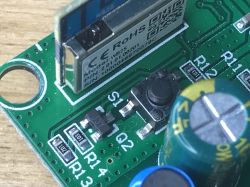
J3Y as usual S8050.
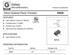
To control the relay there is also a transistor (also S8050) and of course a protection diode parallel to the relay winding:
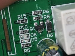
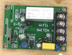
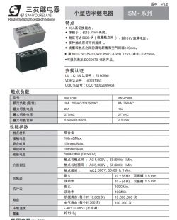
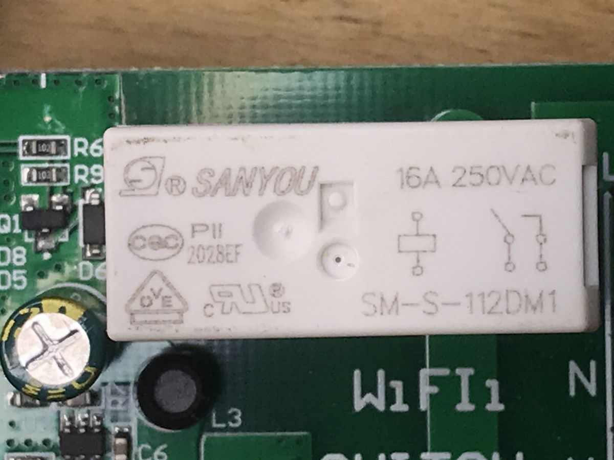
The relay is actually at 16A:

This is SM-S-112DM1 16A 250VAC from SANYOU.
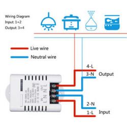
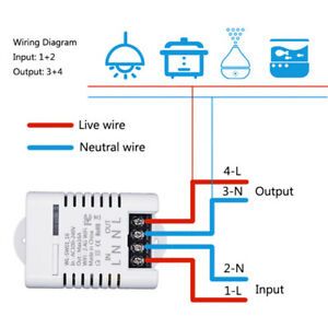
The relay cuts off only the phase:
(or actually: cuts the phase when we connect the wires correctly ... but that's known)
Measurement A few more measurements to confirm what I wrote. Behind Greatz's Bridge:
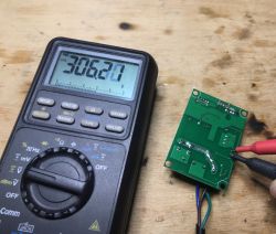
12V with SM7033P:
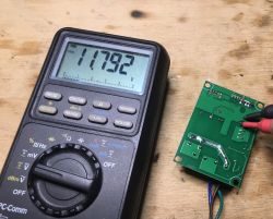
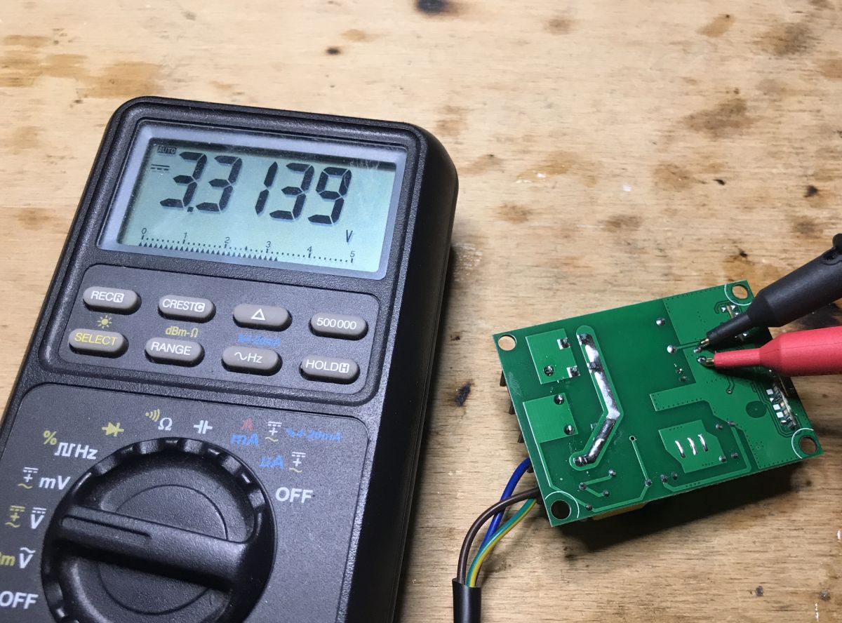
3.3V for the step down converter:

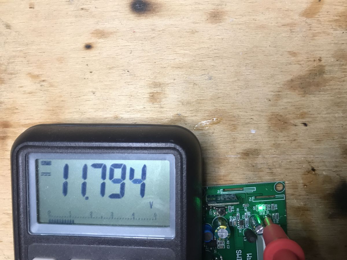
12V on the transistor from the relay control (the relay requires 12V):
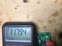
So basically the 12V is there for the relay. It is the relay that dictates the use of 12V, which in turn necessitates the use of a separate step down circuit to obtain 3.3V. Probably if there was another relay, the SM7033P could be 5V, and 3.3V would be taken from the usual (cheaper?) LDO.
Summary This product is not so bad, but it is also not something that we want to buy if we want to upload our own batch and become independent from the manufacturer's servers. There is no ESP8266 / ESP8285 in the measures, only WB2S. So at most we can use it from Home Assistant via Smartlife / Tuya plugin, but then we will not skip the manufacturer's servers.
As far as the construction of the product is concerned, it is quite good, inside there is even a step down converter to get 3.3V from 12V (instead of the common regular linear regulator, which would have greater losses and would emit more heat).
Yeahand you have to remember that this circuit only cuts off the phase (as long as we connect the wires correctly), zero is always connected.
PS: I am enclosing the catalog notes of the inside systems for the inquisitive. If someone comes up with what layout is behind WBCKC, please let me know too.


Comments
This is one of the most important "features" of these products which, in my opinion, disqualify them. [Read more]
However, the lack of ESP does not completely disqualify such a product, because, for example, in the case of the XR809: https://www.elektroda.pl/rtvforum/topic3771510.html I checked and showed that everything... [Read more]
I think that a description of such an experience would be more interesting than another gadget from a well-known Chinese portal ;) [Read more]
Exactly - not the same. ESP is clearly visible in the photo. There is also another tile. [Read more]
And in another photo from the same seller, you can see that the housing is the same as mine (and signed WL-SW01_16). And the PCB is very similar, it is probably an earlier version, but I would approach... [Read more]
Unless everything in the name of smart is done as smart on-off; p As for me, the system that works only with the manufacturer's servers is out of the question. Why? The Chinese will shut down the... [Read more]