Open source firmware was built for the XR809/XR3 WiFi module, turning a door sensor into a Tasmota HTTP and Home Assistant compatible device.
The firmware uses the XR809 SDK in C on ARM Cortex-M4F, reuses the built-in shttpd web server, and adds GET handling for status, pairing, reset, and LED control.
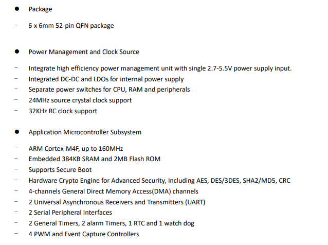
XR809 runs at 160MHz and provides 384KB SRAM plus 2MB Flash ROM.
Tasmota Control and Home Assistant could read the door and button states, and Home Assistant could also switch the onboard LED.
The implementation is still early and messy, with buffer-overflow concerns and WiFi resets when batteries were too discharged.
Generated by the language model.
Hello Here I will present a step-by-step process of writing my own open source firmware for the XR809 / XR3 WiFi module using the example of a door opening sensor. My firmware for it will be compatible with Tasmota HTTP protocol and will allow it to be used independently of the manufacturer's servers. It will also give us compatibility with Home Assistant and Tasmota Control application from Google Play. Perhaps it will be the first such open source firmware in the web for this module.
The software here will be created in C on ARM Cortex-M4F and it will be my first encounter with ARM.
What will we gain from creating open source software? The situation here is the same as with ESP8266 and Tasmota/Domoticz vs. original manufacturer firmware. By using the open firmware, we gain:
- independence from the manufacturer's servers (e.g. if the manufacturer shuts his server down, our device will continue to work)
- no tracking and data collection from the manufacturer (some people are concerned about their privacy, some do not care)
- compatibility with other open source solutions (e.g. here it will be possible to easily connect the device to Home Assistant directly)
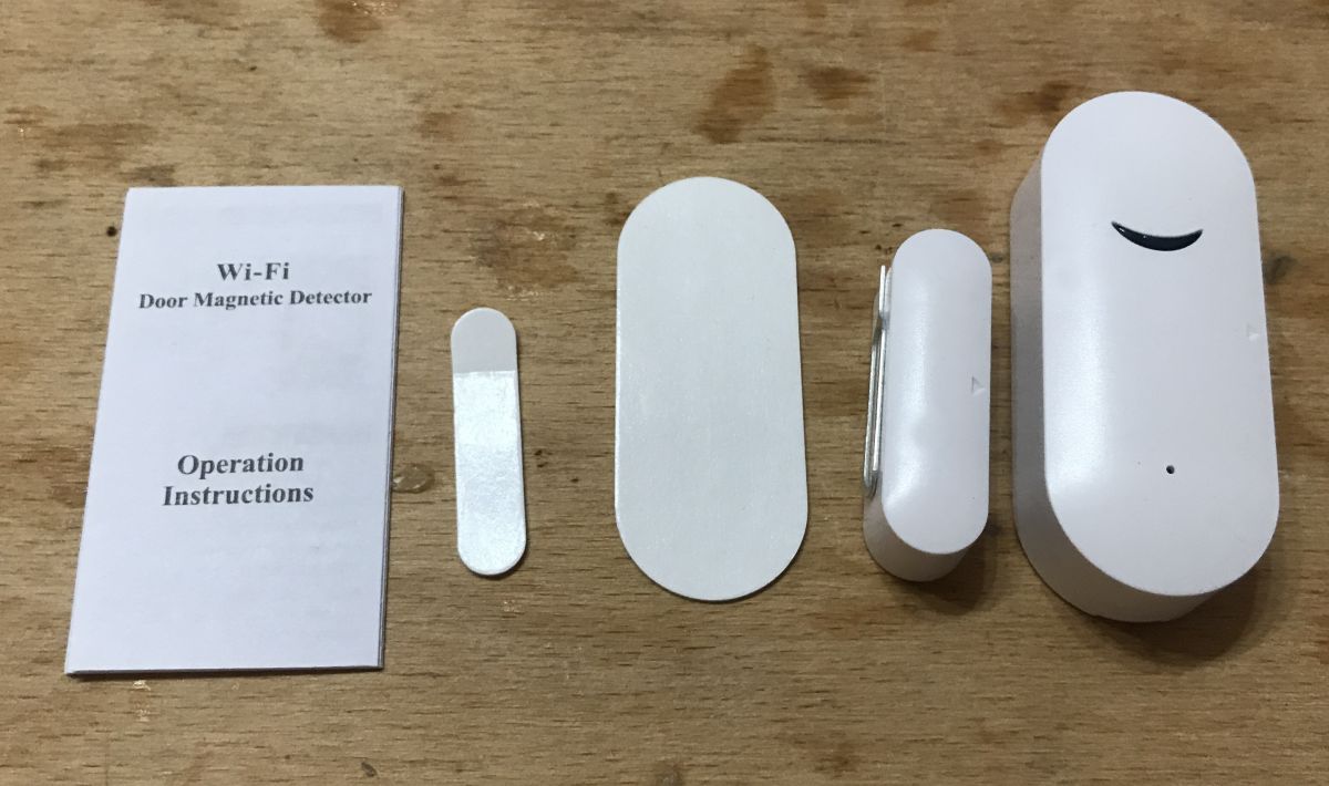
XR809 door sensor used You can find more information about used XR809 / XR3 door sensor there:
https://www.elektroda.pl/rtvforum/topic3771510.html Kit picture:
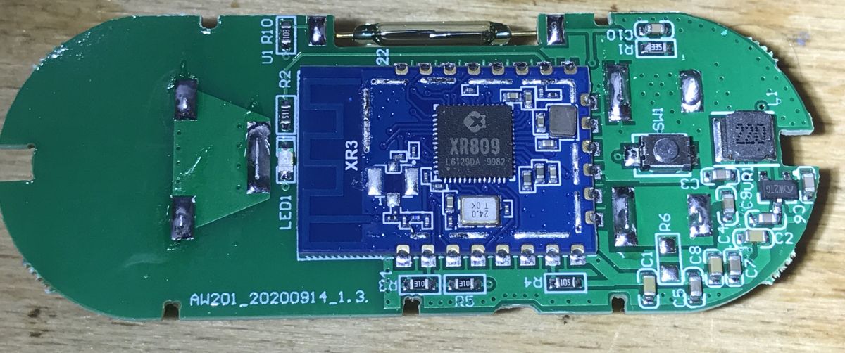
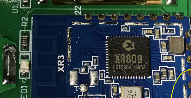
Photo inside:
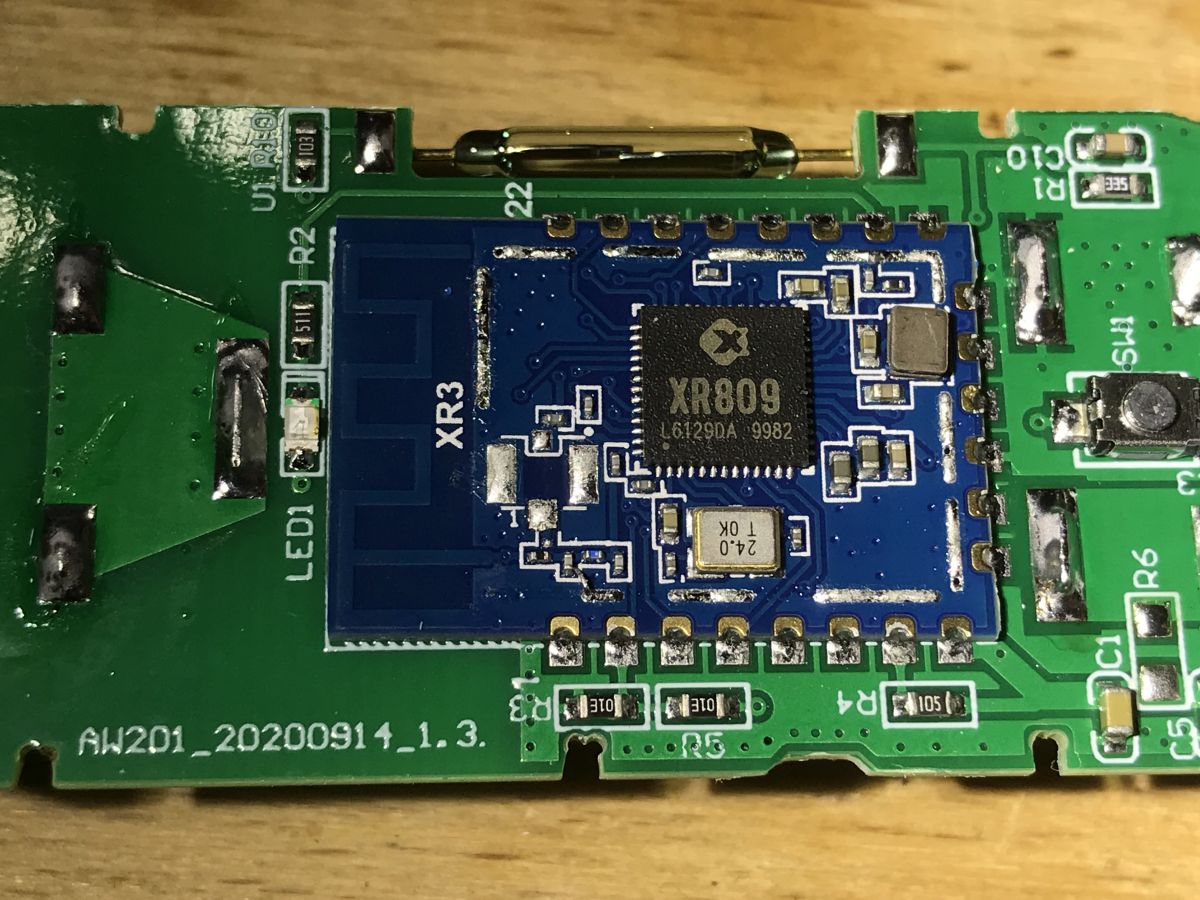
XR809 is the ARM Cortex-M4F microcontroller operating at a frequency of 160MHz, offering 384KB SRAM and 2MB Flash ROM, additionally having rich peripherals, including UART, TWI, SPI, PWM, IrDA (T / R), SDIO and ADC:
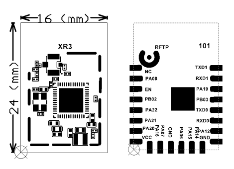
The module itself is called XR, its pinout:
What will be descibed here? Let's first create a short write-up of tasks that we will have to complete in order to create our own firmware for XR809.
Organizational tasks:
- preparation of the hardware connection necessary to upload the firmware (in case of XR809 an UART adapter is enough)
- preparation of the software that uploads the firmware from the computer to the chip (for XR809, it's called phoenixMC.exe)
- preparation of toolchain (compiler) and XR809 SDK
Tasks to be implemented in code:
- our firmware must offer a simple website (both for configuration and for Tasmota HTTP)
- our firmware must be able to read the state of the button and door opening sensor
- our firmware must offer pairing and RESET functions (we must be able to somehow enter our WiFi credentials once)
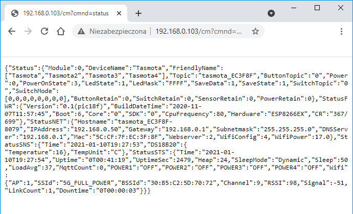
Tasmota HTTP protocol All Tasmota HTTP can be visualized with one GET request sent via HTTP from the client (here: phone from Tasmota Control or machine with Home Assistant) to the server (our XR809 device).
GET query:
This answer is in JSON format.
This is a necessary minimum which allows you to read the status of the device. The state of the device is in two places:
- Power ": 0 - here the 0 is a bit-coded state of successive relays (or buttons). The number is written as decimal.
- "POWER1": "OFF", "POWER2": "OFF", "POWER3": "OFF", "POWER4": "OFF", -the relays/states are here repeated, but in a readable format. The number of states is automatically determined from the table ["Tasmota", "Tasmota2", "Tasmota3", "Tasmota4"] .
Setup of the work environment - Cygwin Cygwin is necessary if we want to be able to compile XR809 firmware on Windows. Cygwin is an environment that mimics the Linux command prompt. It is needed here because the makefile from the XR809 SDK uses Linux commands like cp to copy the results of libraries compilation to a given folder. That's the only reason why Cygwin is necessary.
We can download Cygwin from here:
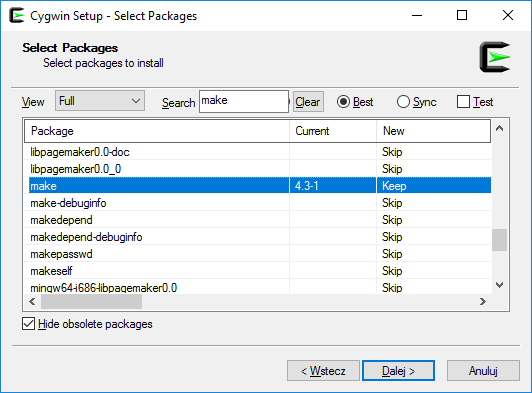
https://cygwin.com/install.html During installation, after choosing to install from the network (Download) and the server from which we want to download packages, we have to select the components that we need:
We need search tthe list and mark here make .
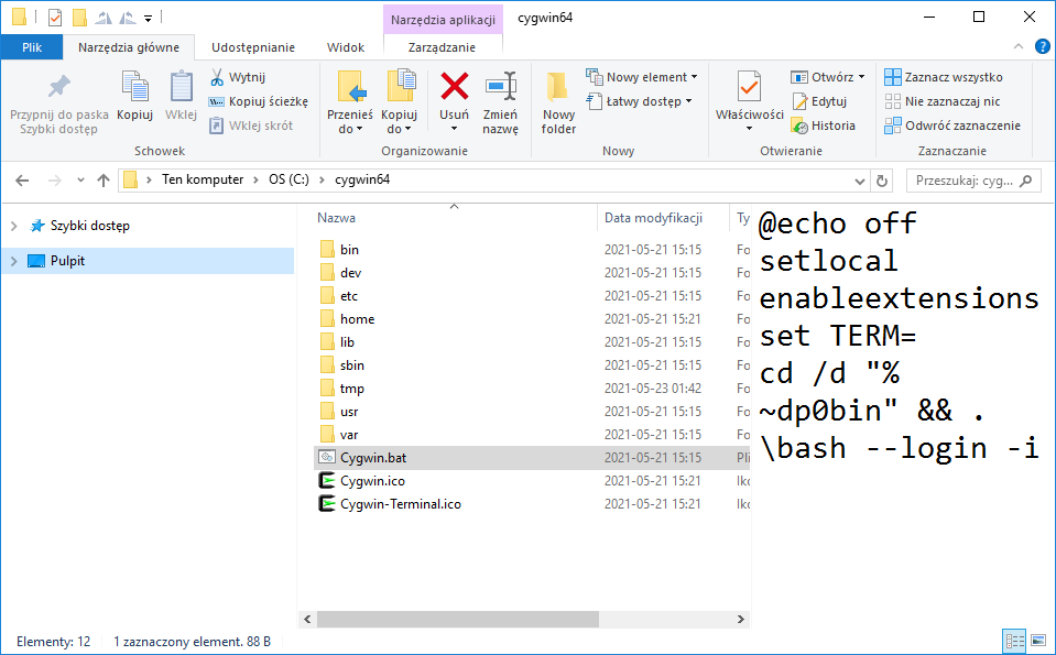
After installing Cygwin, run the bat file:
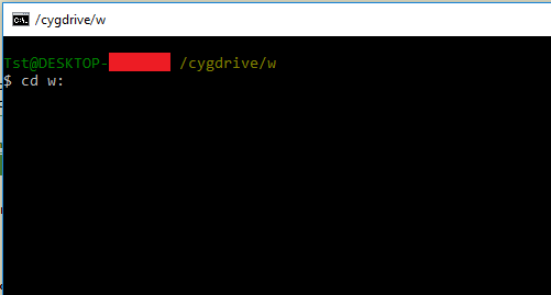
This is how we get a Linux command line on Windows:
This is just like Linux terminal, the navigation is the same, except that when we want to go to disk partition D, for example, we type "cd d:" and it works, it just creates an artificial path /cygdrive/d
Setup of the work environment - ARM toolchain The toolchain needed is gcc-arm-none-eabi-4_9-2015q2-20150609.
You can download it here:
https://launchpad.net/gcc-arm-embedded/4.9/4.9-2015-q2-update I chose the version for Windows and unpacked it to disk, while correcting the path so that there were no spaces (they might confuse stuff a bit, you have to remember about the quotes ...).
In the end, the toolchain path for me came out like this: In: /GNU/4.9.2015q2/bin
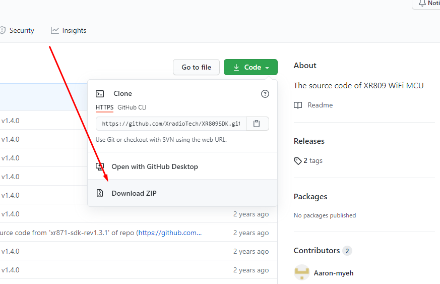
Preparation of the work environment - XR809 SDK from Git We download the XR809 SDK from git, here:
https://github.com/XradioTech/XR809SDK/ You can do it by just by clicking "Download Zip" here:
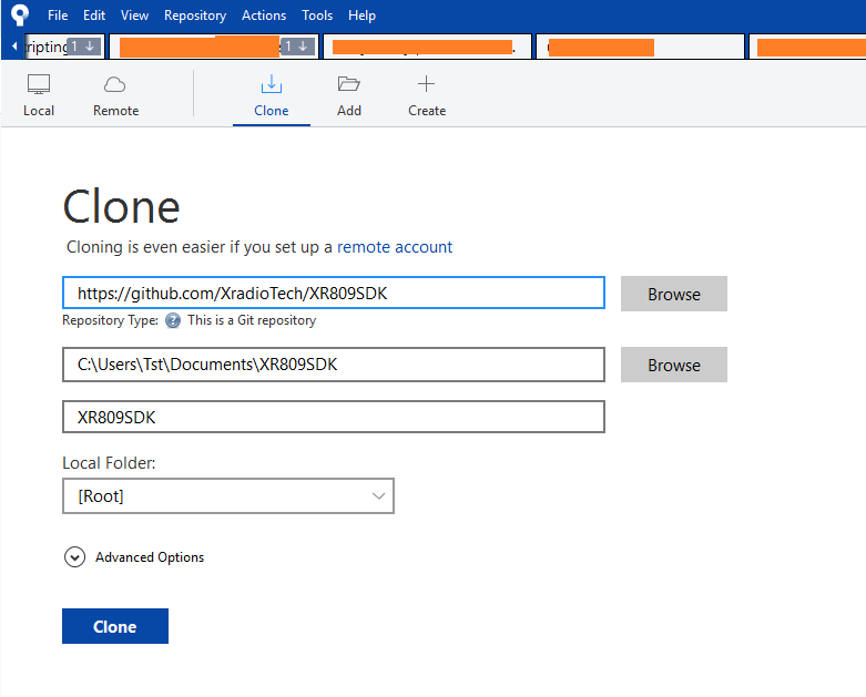
Or you can download it via Git, you can use the command line or graphical interface, here I'm using Sourcetree:
After extracting/downloading, we need to update one file, gcc.mk .
We need to enter the cygwin path to the toolchain there:
Code: Bash
Log in, to see the code
Here we are using Cygwin path, i.e. access to the disk via /cygdrive/ .
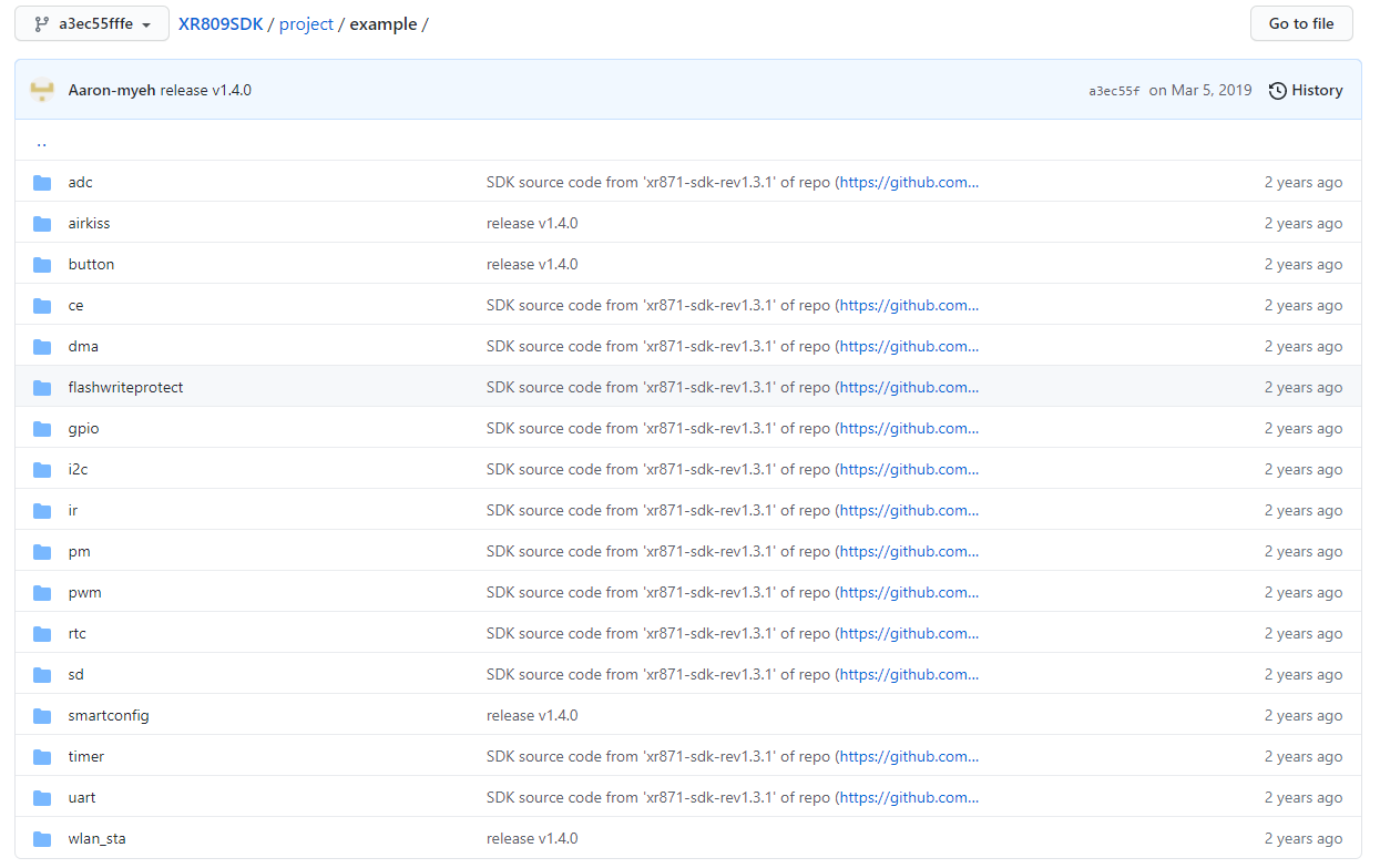
XR809 SDK content from Git The SDK package is divided into shared libraries and separate examples.
Shared libraries are in a folder /src/ .
Larger examples are at /project/, smaller examples are at /project/example/, for example:
Build process Firmware build for XR809 (and similar) is done in two steps. First, we compile the shared libraries, this folder:
XR809SDK/src/ Then we compile the selected project, for example:
XR809SDK/project/at_demo/ Compilation consists 4 commands.
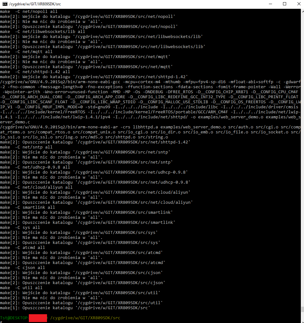
Step 1.1:
In the directory /cygdrive/w/GIT/XR809SDK/ src we do make.
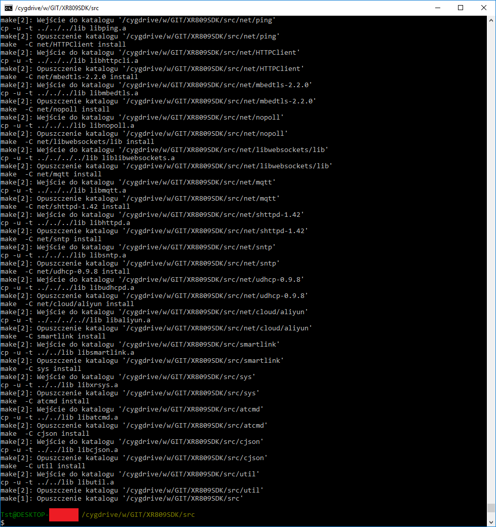
Step 1.2:
In the /cygdrive/w/GIT/XR809SDK/src folder, we run make install.
NOTE: this step requires linux cp command (copying files), so we run it in Cygwin. Windows doesn't have a Linux "cp" command in cmd, it does have its own (you could change the make build script to use Windows command set, but it's easier to use Cygwin).
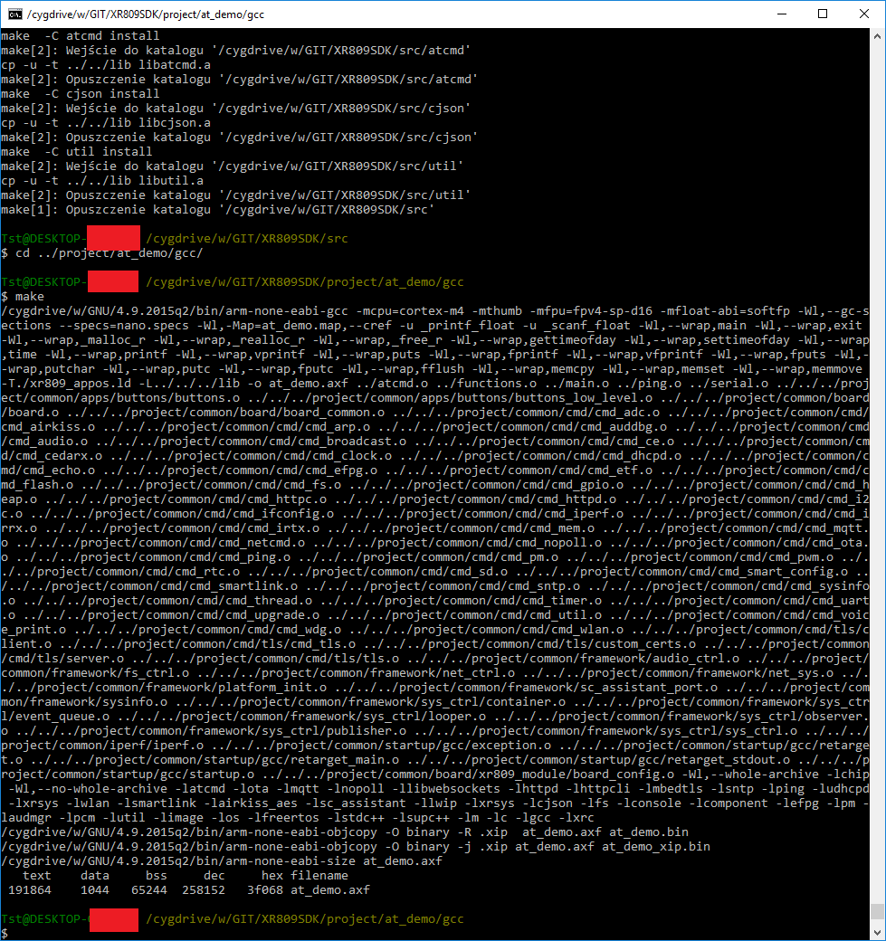
Step 2.1:
In the /cygdrive/w/GIT/XR809SDK/project/at_demo/gcc folder (or in the project folder we selected), make:
Step 2.2:
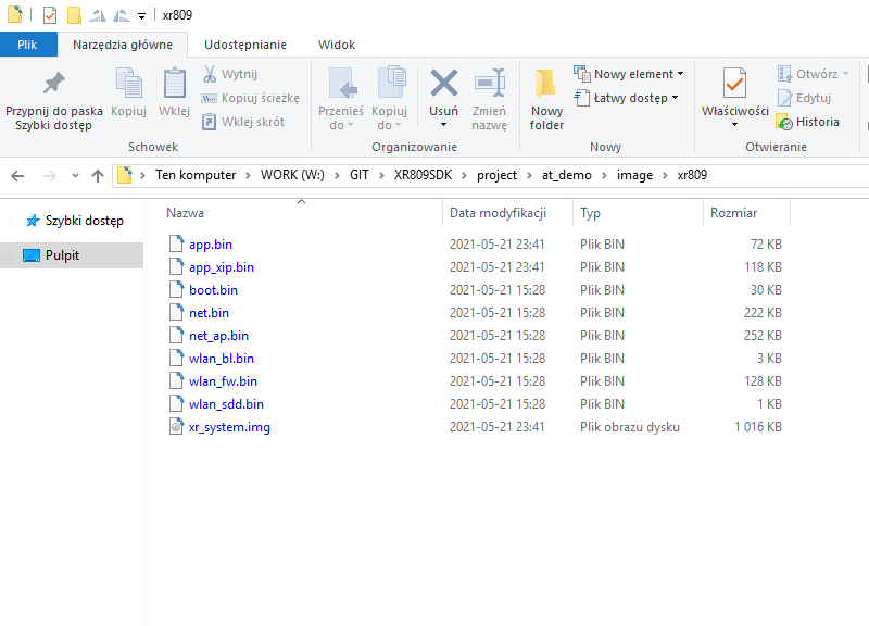
In the same folder - make image:
This command will use mkImage.exe to generate xr_system.img (which we will then upload to XR809 via UART).
Result:
Simplify the build process This step is not required, but I think that build process is too complicated and uses too many steps.
Let's simplify it and create a Bash script that will do it all with one command.
It's a linux script, but in cygwin it will of course work.
Code: Bash
Log in, to see the code
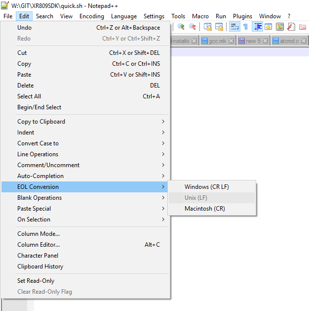
If we get some errors related to \r (carriage return), it means that we wrote it with Windows line endings standard (\r \n) and we need to convert it to unix line ending. This can be easily done in, for example, Notepad 2:
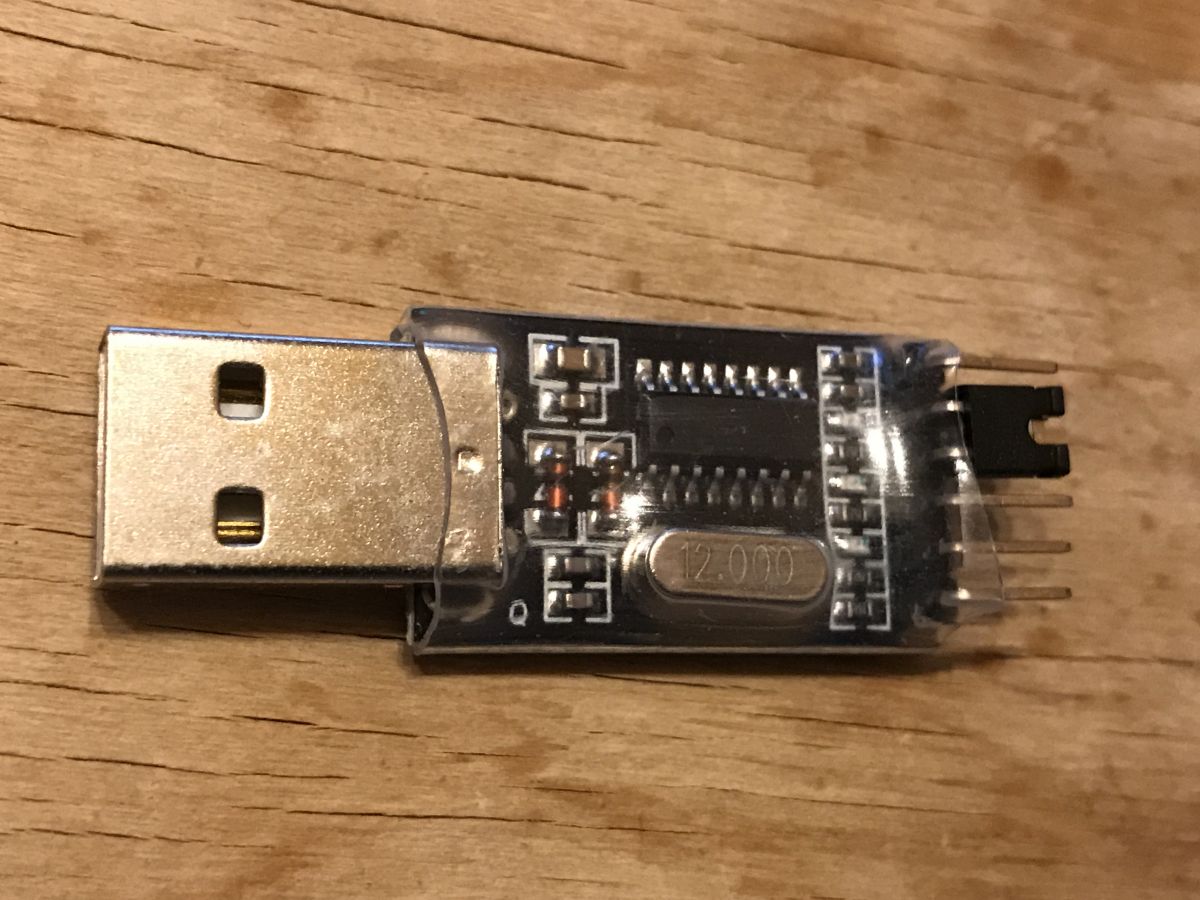
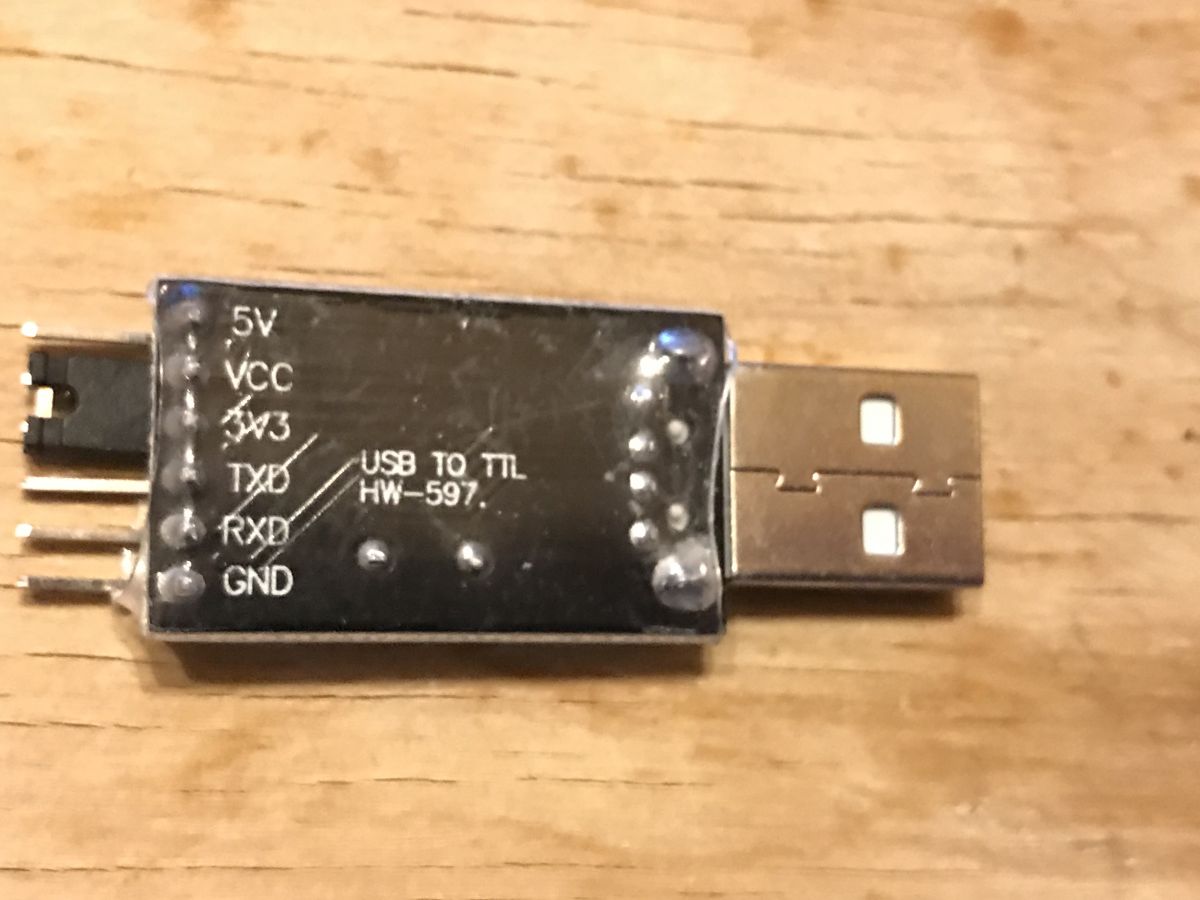
Hardware connection XR809 is programmed via UART just like ESP8266.
So let's prepare the cheapest dongle, USB TO TTL HW-597 (jumper set 3.3V logical levels):
In addition, according to the catalog note:
datasheet wrote:
During firmware burning, both PB02 and PB03 need to be connected to a low level. When the module works properly, PB02 and PB03 cannot be connected to a low level
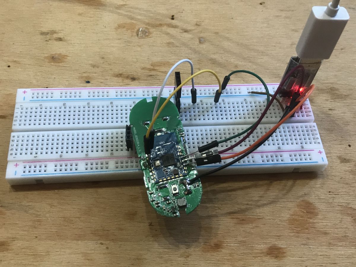
For this pin EN - otherwise RESET - (to be able to reset the system). The board is battery powered.
So the connections made:
Burning the XR809 firmware The compiled firmware is in file xr_system.img , this can be found in XR809SDK\project\at_demo\image\xr809 .
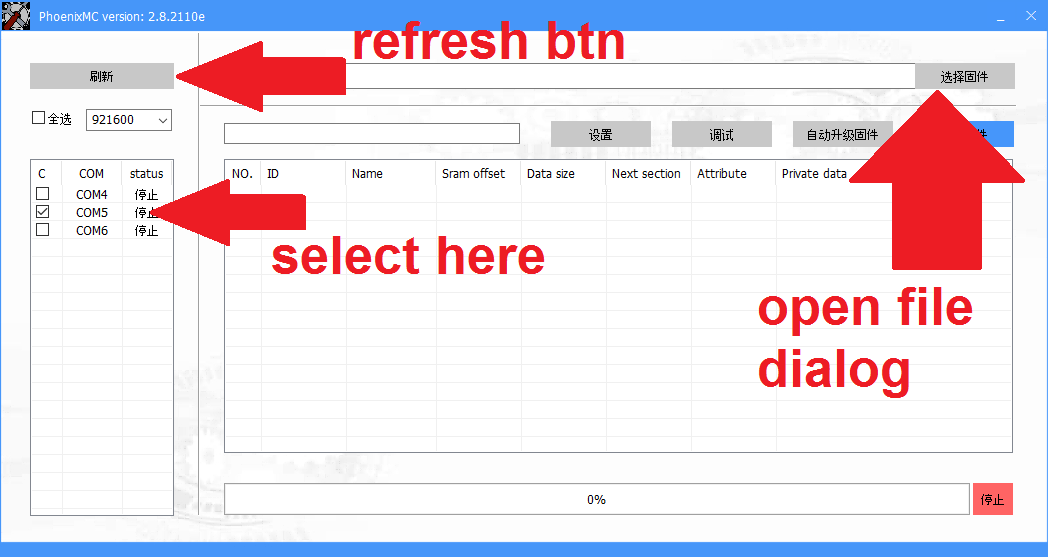
Now we need to use the programmer software, phoenixMC.exe This program requires that the UART port is not in use, so remember to close the port in Realterm or whatever terminal we are using.
This phoenixMC.exe has chinese interface, but I figured out how to use it.
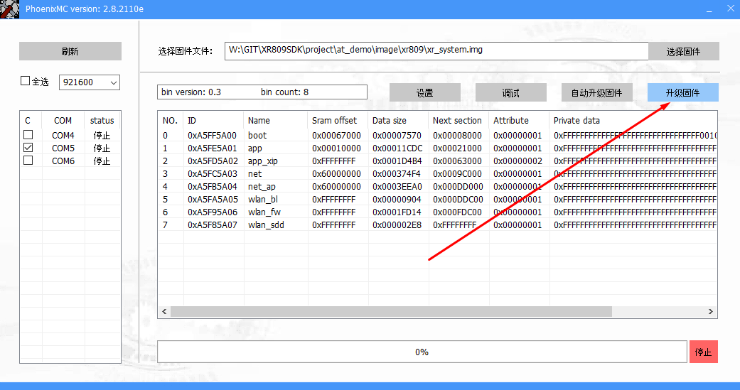
Here are the steps on the GUI (we open the generated img file):
On the hardware side:
1. connect RESET to ground
2. connect PB02 and PB03 to ground
3. disconnect RESET from ground (it can be in the air)
In other words, while booting, PB02 and PB03 must be on ground to enter programming mode.
datasheet wrote:
During firmware burning, both PB02 and PB03 need to be connected to a low level. When the module works properly, PB02 and PB03 cannot be connected to a low level
Then click Burn:
It should start uploading the firmware:
Upload ready:
Then we start XR normally, that is:
On the hardware side:
1. connect RESET to ground
2. disconnect PB02 or PB03 to ground
3. disconnect RESET from ground (it can be in the air)
Let's try running the XR809 AT firmware We already know how to compile and upload the firmware. So we can upload the AT firmware (after its compilation, its binary files are not on the repo).
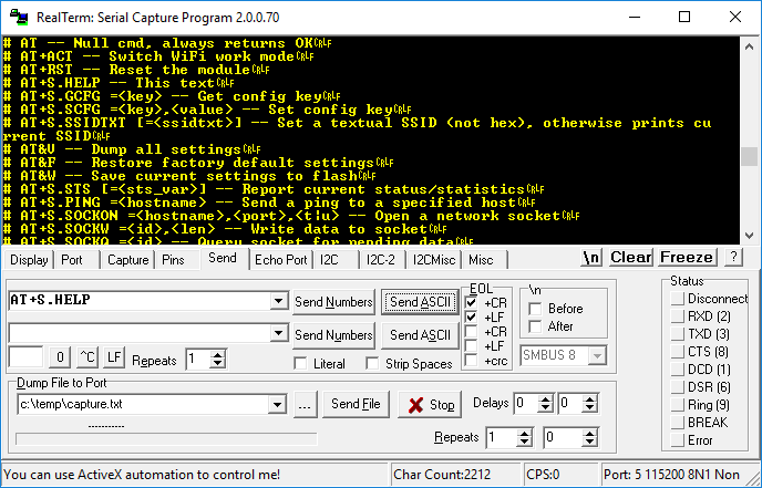
Now we should be able to execute commands via UART. The default baud is 115200.
Let's check the command AT + S.HELP (remembering CR LF, line feed and carriage return):
AT works.
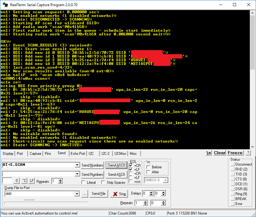
Now let's try the command AT + S.SCAN .
The module sees the WiFi network. We are able to communicate with him.
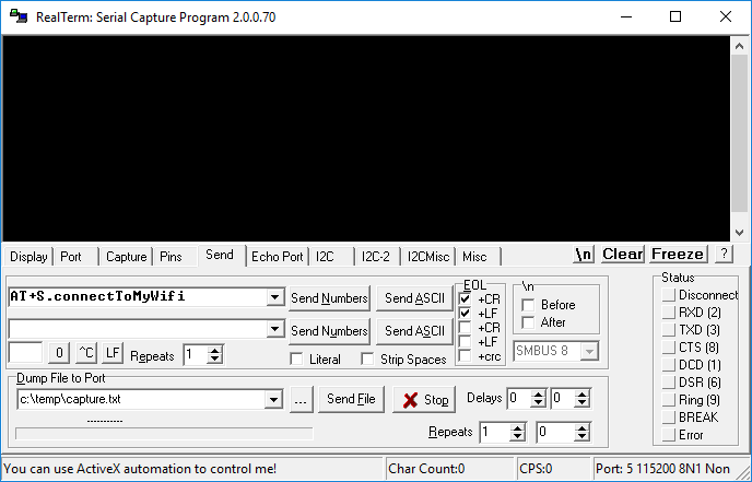
Creating our own AT command for XR809 Well, let's start with something easy. We will add our own command to AT project. This command will connect XR809 to our WiFi. Of course, the final version of our firmware will not be using AT, but it's worth doing something like this just to check if everything is working correctly.
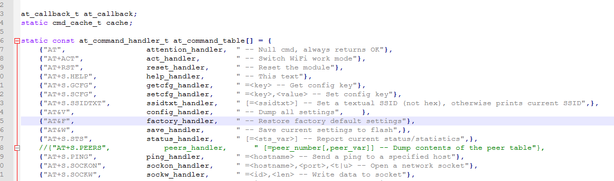
Commands are in at_command.c :
Here is a simple C table of command names, pointers to functions that handle them and short descriptions of these commands (for generating Help).
I used Notepad2 to edit the code (throughout the topic). I added new command at the end:
Full function code (remember to add #include):
Code: C / C++
Log in, to see the code
This command will connect XR809 to our WiFi.
Does our command work?
We can find out about the success of the process from the router logs.
In addition, it is worth checking if this is the MAC address that XR has (in AT there is a command to know it) and whether the ping command sees it (and ceases to see when we disconnect the power).
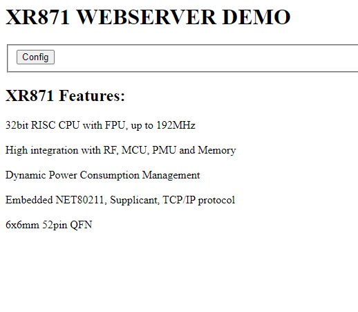
The first HTTP server After a brief look at the SDK, you can see that the HTTP server library is ready to use.
Is in src\net\shttpd-1.42 .
The HTTP server demo is also ready, here: src\net\shttpd-1.42\examples\web_server_demo.c Let's try to run it. Server setup will be called from command we added earlier. Of course you have to add #include etc, but surprisingly the files were already compiled (a bit strange that they compile web_server_demo.c for the shared library..):
Code: C / C++
Log in, to see the code
After uploading the firmware and executing the command, the server works:
By the way, you can see that it was a server for a related chip, XR871, not for the XR809 I am using here, but I guess they are basically the same.
We will use this server as a base for Tasmota HTTP support.
Implementation of GET packet handler After a brief analysis of the code from the XR809SDK\src\net\shttpd-1.42\examples\web_server_demo.c you can easily see how the GET request handling for a given URL is added:
Code: C / C++
Log in, to see the code
You just have to provide the path and a handler function pointer.
So it's time to use shttpd_register_uri and add support GET /cm?cmnd=status HTTP/1.1 .
shttpd_register_uri takes as arguments a pointer to context (ctx), a URI path, and a pointer to a function.
To create my function, I copied and changed set_ap_info :
Code: C / C++
Log in, to see the code
GET registration:
Code: C / C++
Log in, to see the code
The result in the console after sending a GET:
There is still some kind of issue with parsing GET arguments, but we will fix it later.
The result in the browser:
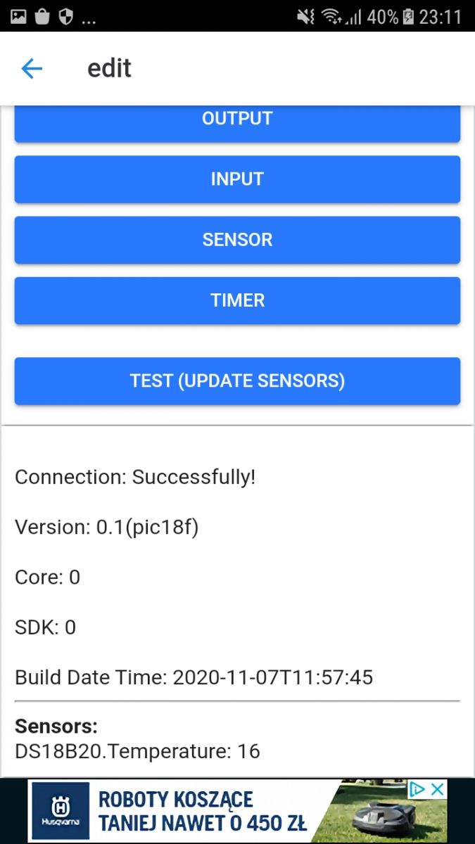
And now the best part - it is now already compatible with Tasmota Control from Google Play.
https://play.google.com/store/apps/details?id...s_software.TasmotaControl&hl=pl&gl=US After adding device by IP, the result in Tasmota Control:
Of course, all these data are placeholders, i.e. everything is hardcoded.
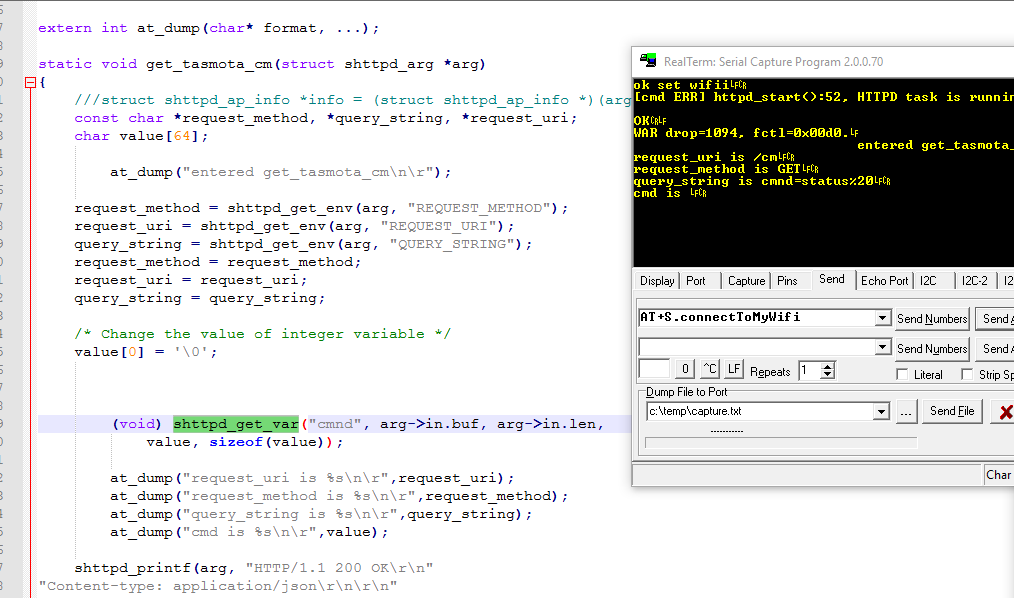
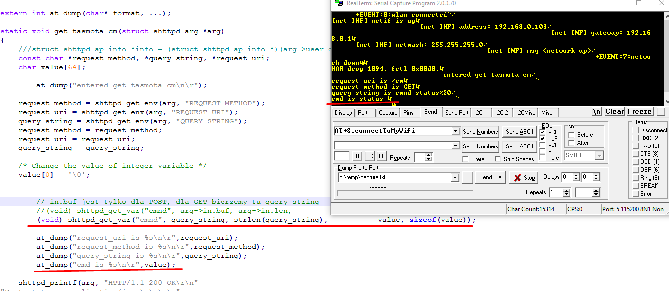
Parsing of GET parameters For a moment I was wondering why GET parsing is not working for me. This function is responsible for him:
(void) shttpd_get_var ("cmnd", arg-> in.buf, arg-> in.len, value, sizeof (value)); For POST it worked.
But the implementation of the function is self-explanatory.
Code: C / C++
Log in, to see the code
arg->in.buf is an argument text buffer for POST, not GET.
For a GET, it needs to be given a string of GET arguments, like this:
(void) shttpd_get_var ("cmnd", query_string, strlen (query_string), value, sizeof (value)); After this change for the query GET /cm?cmnd=status we get:
This way we can extract the values of the GET arguments.
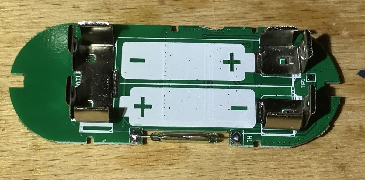
Reading the door status Now it's to consider how can we read the door status from this sensor:
This sensor responds to the magnet, the magnet makes the contacts touch. In my opinion, it is enough to read the pin in digital mode.
I found examples of digital IO pins handling in XR809SDK/project/example/gpio/main.c
Code: C / C++
Log in, to see the code
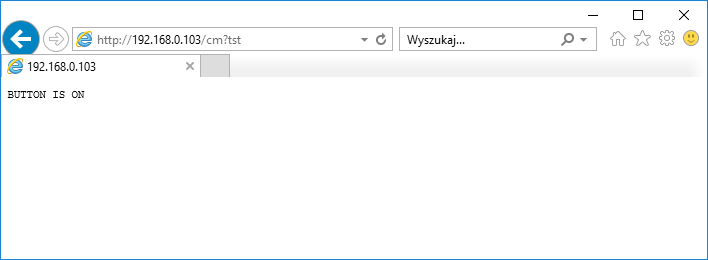
So I pasted them into the fragment of code I was testing and I also added a test-only request "tst" in the query string to check if the sensor detects something.
Code: C / C++
Log in, to see the code
Door state display (only to check if it works, will be removed in next version):
Code: C / C++
Log in, to see the code
And now, after uploading our firmware, it's time to check if door sensor works.
Test care - "Door closed":
Test care - "Open doors":
It works - it's time to integrate it with Tasmota HTTP.
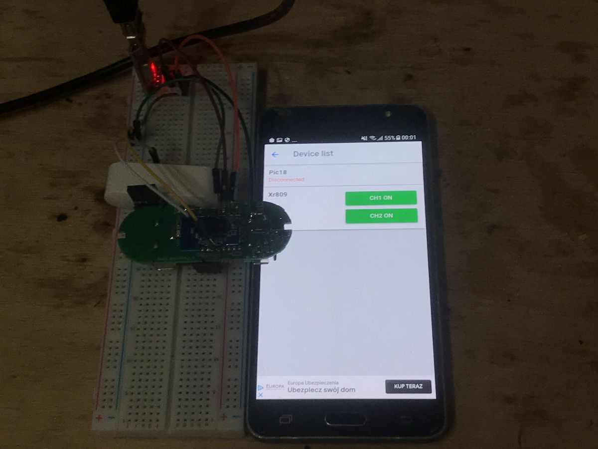
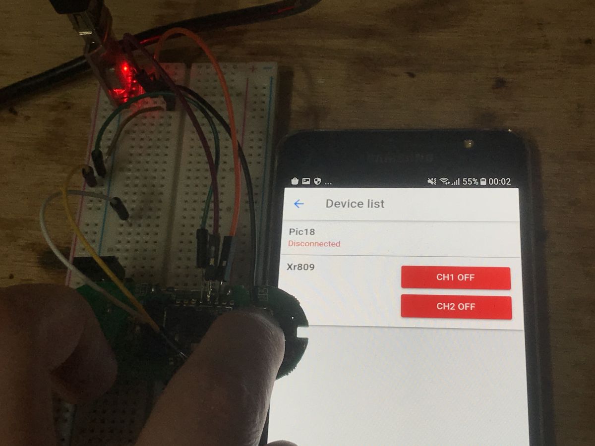
The first signs of functionality I cleaned up the code a bit and also connected the button from the board as the second input. Below is the code for generating the response to the Tasmota HTTP query (code specially written quite clearly, it could be done better and shorter, but less readable for beginners):
Code: C / C++
Log in, to see the code
Result in Tasmota Control:
With active sensor ("closed door"):
With the button pressed:
So everything works.
The history in the UART console shows how often Tasmota Control polls the XR for the status:
Reset to AP mode - button on the HTML page At the moment, my WiFi SSID and password are hardcoded into the firmware. I will now try to fix it.
It should be possible to enter WiFi data on the XR809 page.
First, I will add a website button to change XR809 wifi into an open Access Point.
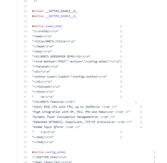
The XR website is at src/net/shttpd-1.42/examples/source.h.
"Reset AP" button added:
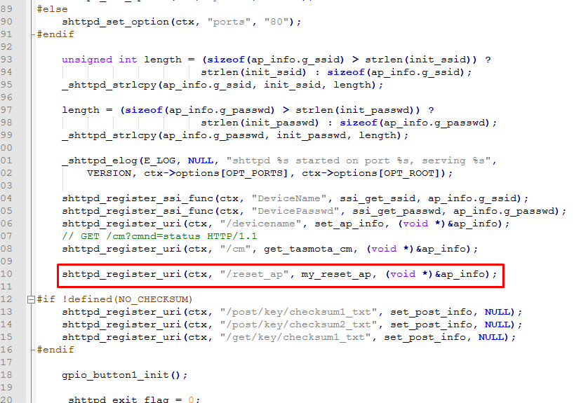
We also need to add GET query support, just as before, this time for path /reset_ap:
And the function to handle it:
Code: C / C++
Log in, to see the code
(I note right away that it would be better to wait 1 second in the main loop and then change the network state, because in the current version we will not get a response to this GET because the XR809 will disconnect immediately)
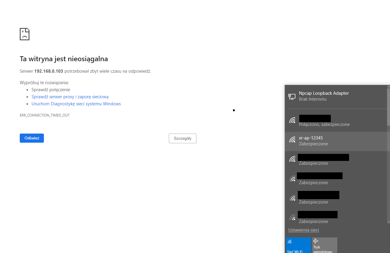
After pressing the button, we lose contact with the module and its WiFi network appears:
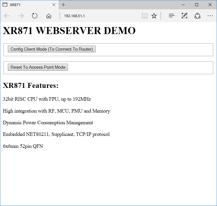
After connecting to this network, at IP address 192.168.51.1, we can reconfigure the module:
Here is our password and SSID (you still have to make the field to be of the password type, but it's not a problem, it's an HTML issue):
(actually I did not create an open AP here, but an AP with a known SSID and password, but it's the same. You could also add randomization of this "12345" in the SSID so that it includes the MAC for example)
Reset to AP mode - physical tactile switch on the PCB Now we need to create something similiar to well know physical button reset process for smart devices.
We will make that pressing the on-board button for 5 seconds resets the device to the default AP (XR creates a WiFi network itself), so that we can then connect to it and configure it with data about our router.
We need to somehow check if the button is pressed for 5 seconds.
I decided to use the HTTP event polling loop, calling shttpd_poll blocks for 1 second, so just about right:
Code: C / C++
Log in, to see the code
After my changes:
Code: C / C++
Log in, to see the code
This works, but I suspect there's a minor bug here - shttpd_poll doesn't always block for 1000ms, it might block execution for shorter time if a packet arrives.
In the next version, I might change this XR's button library that handles debouncing and things like this by itself:
Code: C / C++
Log in, to see the code
Details in project/example/button/main.c
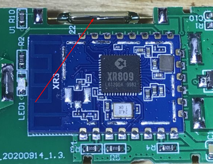
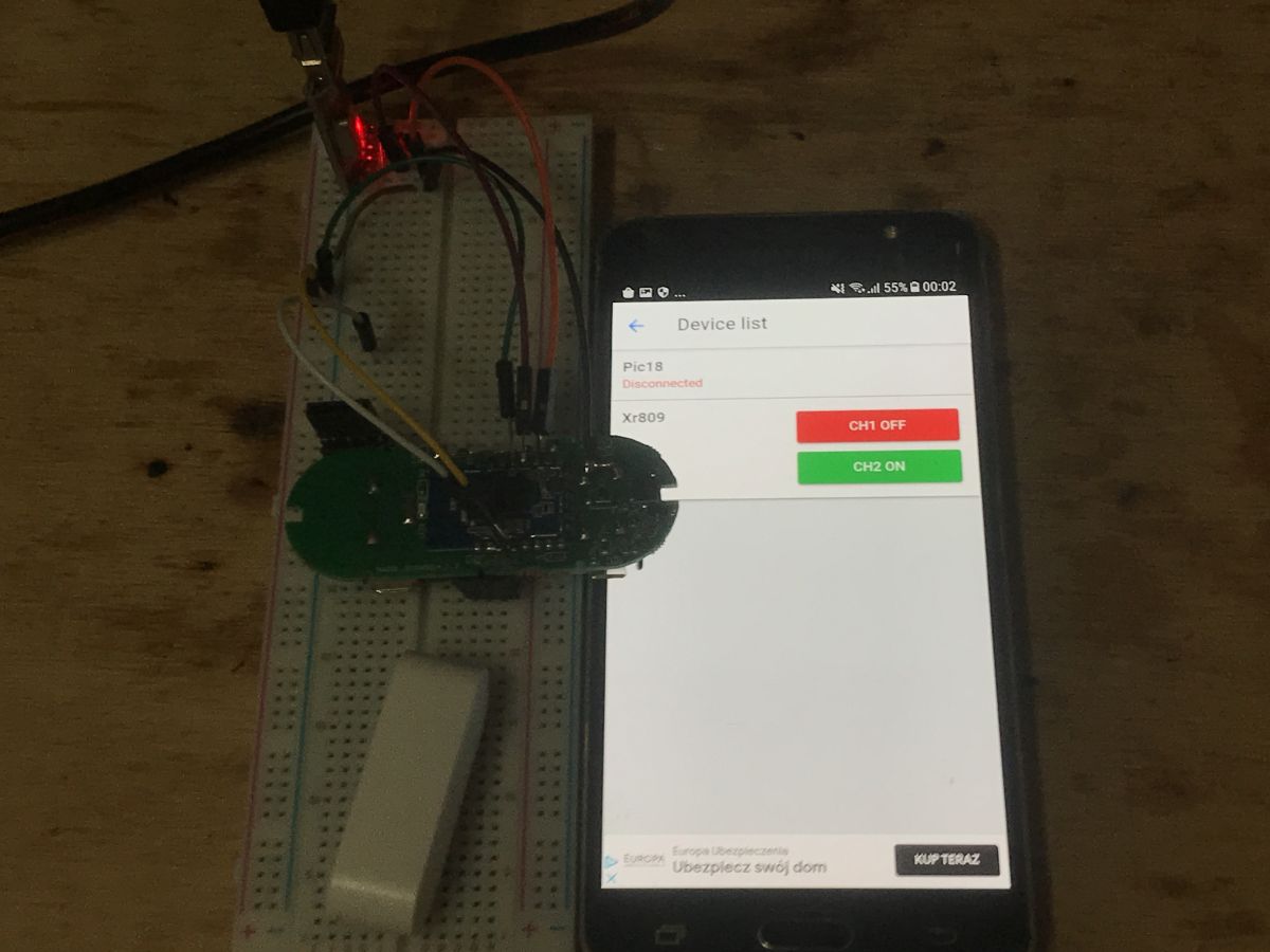
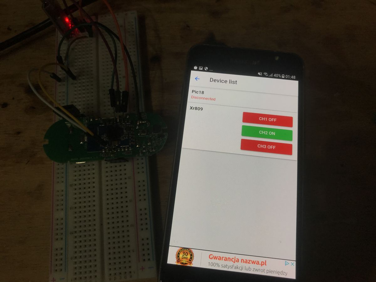
Adding ability to control the on-board LED Now let's try to share the on-board LED with Home Assistant via Tasmota HTTP. This way you would be able to control it any way you want.
It's not really necessary, as the device used here is a door sensor, but I think it can be interesting and useful to show how such thing is done.
The diode is connected here:
So we need to setup LED GPIO, PA12, in output mode:
Code: C / C++
Log in, to see the code
Since we want to see its status through Tasmota HTTP, we need to add it to Tasmota HTTP status packet, for example as "Power3". It needs to be included in the "relays" state array:
Code: C / C++
Log in, to see the code
In the code above, g_gpio_led, str_state3 and "Tasmota3" has been added.
And if we want to be able to control it, we also need to handle the package GET /cm?cmnd=Power1%20Off HTTP/1.1.
"Powers" are indexed from 1 (not from 0), states can be On or Off.
My parsing code for this (very prelimary, without any buffer overflow checks, etc):
Code: C / C++
Log in, to see the code
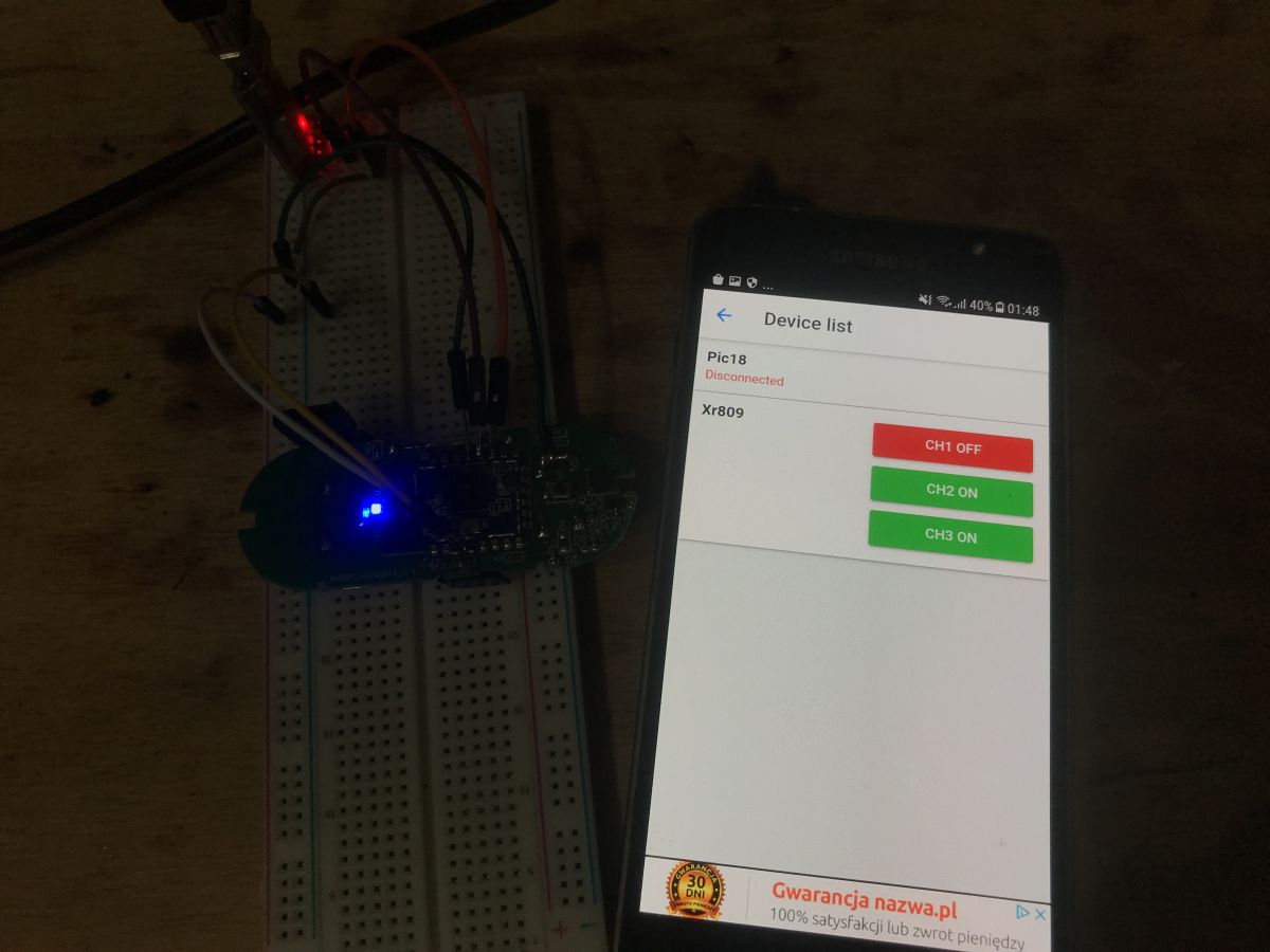
And now, finally, we can blink this LED - via Tasmota HTTP:
One minor fix - the status pack short reply I will not describe it in detail, because this part is purely within the knowledge of the C language in general, and not with XR809, but unfortunately we still have to be compatible with the short Tasmota HTTP response format, i.e. when asked:
(at this point, the program responds to this packet with the entire device status description)
See below for fixed version (and this version is finally compatible with Home Assistant):
Code: C / C++
Log in, to see the code
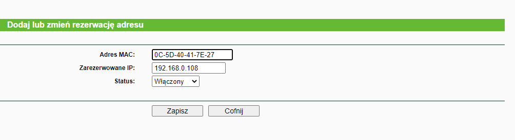
Fixed IP Due to the way Tasmota HTTP works (our device is a server, and we ask for its status), a fixed IP will be useful here. To make things simple, I did it by reserving the IP address for the MAC address on the router:
This could also be done via a specific host name and DNS.
Final test with Home Assistant Finally, I tested the module from Home Assistant using the Tasmota HTTP support Python scripts described here:
https://www.elektroda.pl/rtvforum/topic3789324.html that is the updated version of this plugin, HTTAS by JiriKursky:
https://github.com/JiriKursky/httas ATTENTION - for the moment httas version from Github will not work with newer Home Assistant versions . This is due to a change in the way coroutines are handled. You will get an error: " ValueError: Coroutine not allowed to be passed to HassJob . "
Therefore, I recommend downloading my corrected version:
httas-fixe...210306.zip (6.91 kB)You must be logged in to download this attachment.
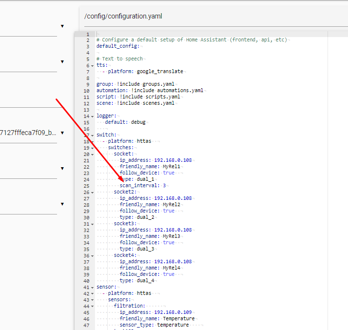
In /config/configuration.yaml I set up the device location:
Code: YAML
Log in, to see the code
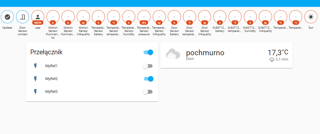
Then you need to reboot Home Assistant. In my case, it immediately detected XR809 after booting up:
"MyRel1" here is the door open state, "MyRel2" is the button state, "MyRel3" is the LED state.
The status of the LED can be changed from the Home Assistant. The other fields are read-only.
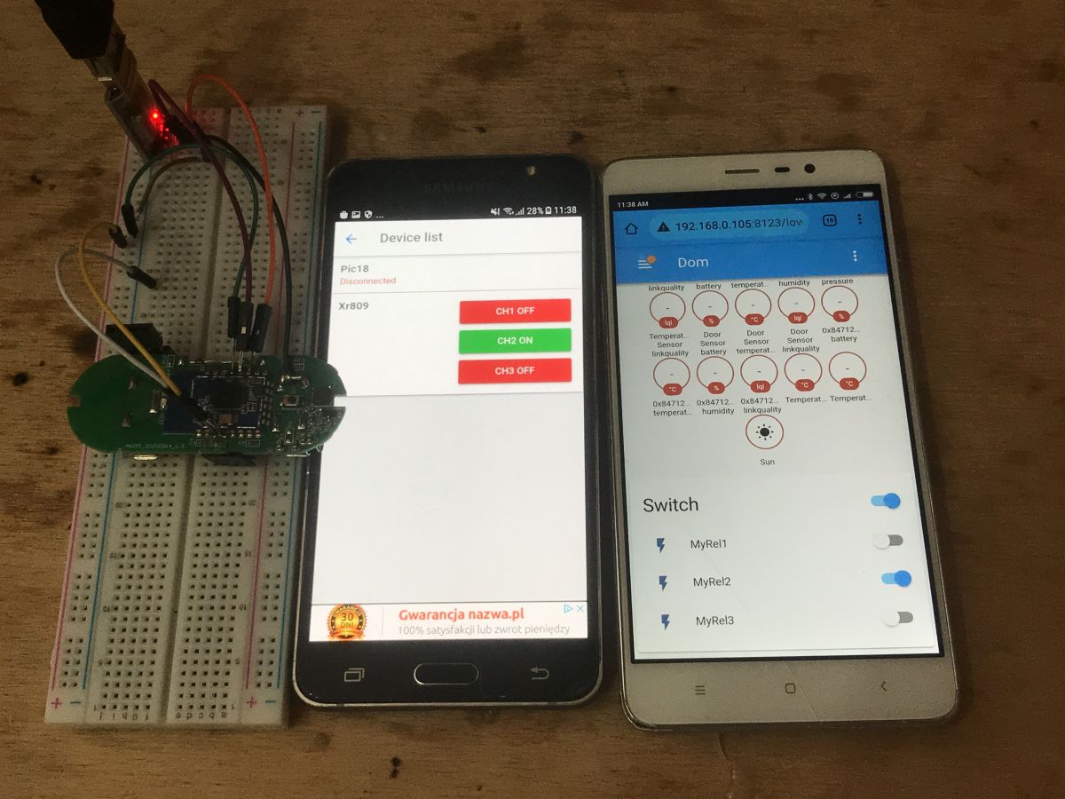
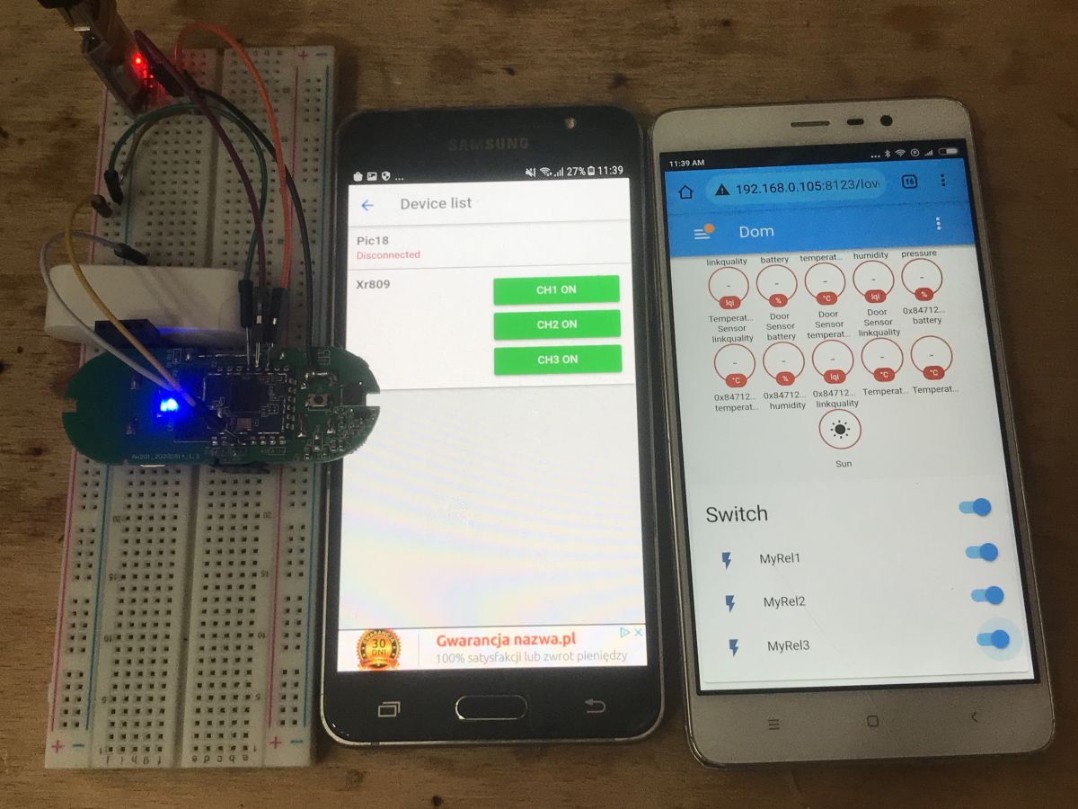
Short demonstration:
Automations in Home Assistant My firmware allows us to do automations in the Home Assistant, for example, opening the door will turn on the LED (in its place you can put any HA compatible device):
Code: YAML
Log in, to see the code
switch.socket is the path to the entity previously set in /config/configuration.yaml
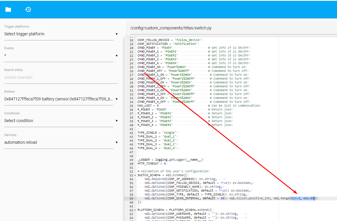
Increased sensor responsiveness In the case of the door opening sensor, the reaction time of HA to a change in door state can be further decreased. This is done in the configuration, just add scan_interval (value in seconds):
If you get an error:
Invalid config for [switch.httas]: value must be at least 3 for dictionary value @ data ['switches'] ['socket'] ['scan_interval']. Got 1. (See?, Line?).
then you can reduce the minimum value in custom_components/httas/switch.py:
I think that the 1 second refresh interval even for the door status is sufficient.
Problems encountered While exploring the XR809, I ran into one, rather unusual, problem. It cost me over an hour of time.
While working on our WiFi configuration system for the board (the RESET button creating an Access Point with a known password) I saw that suddenly the board resets (returns to main ()) when I want to create an AP or connect to an existing one.
The same result had the inclusion of the WiFi network scan - everything reset the board.
What do you think was the reason for this?
Spoiler answer:
Spoiler:
It turned out that during the work, the batteries were a bit too discharged and with their low level, the XR809 resets when WiFi activity starts. I fixed the problem by replacing the batteries with new ones.
The popularity of the XR809 Finally, I would like to make one small, final remark, because I know that not everyone could fully understand my intentions. Of course, I know that the XR809 and related ones are not very popular right now and there is much more ESP8266 devices, etc, but I wanted to show the general method of open firmware creation for an unknown chip. I also know there are some other chips, like WB2S or WB3S and I am also going to try figure them out soon.
For the user - how to use my XR809 firmware My XR809 firmware described here is in a very early development version, but still it's functional.
So here's a short guide on how to use it.
1. Load my xr_system.img via UART to XR809 (from the project /at_demo/image/xr809/directory)
2. Press the button for more than 5 seconds
3. connect to xr-123etc wifi network, password 12345678
4. open 192.168.51.1, enter the SSID and password of our WiFi there on HTML page
5. Add MAC XR809 IP reservation on the DHCP settings of WiFi router (so IP won't change during some network outage or something)
6. In Home Assistant, add the Tasmota HTTP plugin (httas by JiriKursky, in case of any issues, use my fixed version with "coroutines" problem solved)
7. in Home Assistant, add the IP and configuration for our device in configuration.yaml
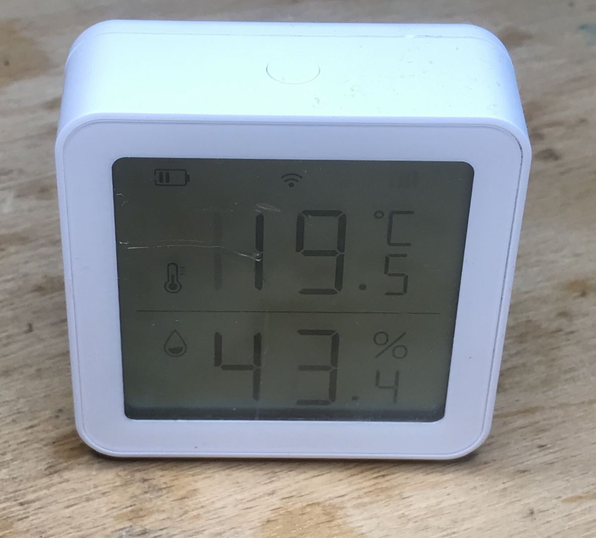
Further plans At the moment, I plan to look at the purchased LCD thermometer / hygrometer, which also houses the XR809:
Then I will probably improve the code presented here a bit. Now it is a bit messy, and perhaps it could be crashed by some buffer overflow (when user sends malicious data). And you probably need to add save() call to save the WiFi configuration to the memory in case of removing the battery, but this is not a problem, because at_demo from the SDK has an example save function.
Summary The firmware developed here has made my XR809 sensor completely independent from the manufacturer's servers and allows me to use it directly with the Home Assistant. Writing this software was basically like assembling it from ready-made components, because everything required was already in SDK, including the HTTP server. The amount of free time and the number of devices with XR809 (XR1, XR2?, XR3) will determine the continuation of the project.
The latest version of my code (entire modified SDK) is attached to this post, but please remember that version is before major rewrite and contains bad coding practises.
Attachments:
XR809SDK-updated-for-tasmota20210523-fx2.zip(24.27 MB)
You must be logged in to download this attachment.
XR809_PIN_Multiplexing.pdf(79.24 KB)
You must be logged in to download this attachment.
XR809_Product_Brief_V1.0.pdf(500.05 KB)
You must be logged in to download this attachment.
XR809_Datasheet_V1.1.pdf(1.72 MB)
You must be logged in to download this attachment.
XR1 Module Datasheet_Tuya Smart_Docs.pdf(555.72 KB)
You must be logged in to download this attachment.
XR3 Module_Tuya Smart_Documentation.pdf(226.92 KB)
You must be logged in to download this attachment.
About Author
p.kaczmarek2 wrote 14635 posts with
rating 12649 , helped 655 times.
Been with us since 2014 year.
Well now it's still a port for BK7231 and you are a famous man ;) [Read more]
p.kaczmarek2
23 May 2021 20:19
So WB2S, WB3S?
SDK for them is also on the network, I already have a flasher:
https://obrazki.elektroda.pl/5184494700_1621793902_thumb.jpg
We'll see how it goes. As long as you have all the... [Read more]
chemik_16
23 May 2021 22:38
there is a whole set for 2 years, but no one has touched it, everyone is soldering these modules to esp.
https://github.com/bekencorp/bk7231_alios_sdk
systems installed in all cheap smart tuyas, such... [Read more]
p.kaczmarek2
28 May 2021 03:08
The chances of the Bk7231 have increased significantly recently.
It looks like I can read (and upload?) The batch to him now:
https://obrazki.elektroda.pl/9480591200_1622157875_thumb.jpg
I can... [Read more]
varguit
05 Jun 2021 23:38
Hi @p.kaczmarek2, first of all congrats for this great job.
I need help with the firmware uploading process, I'm using an old PL2303 USB to TTL (checked with the check tool and OK).
When starting the... [Read more]
p.kaczmarek2
07 Jun 2021 16:26
Amazingly you are right.
In my diagram, RX and TX are swapped.
So here we connect RX to RX, and TX to TX. The producer has a strange convention on the descriptive layer.
https://obrazki.elektroda.pl/8008042300_1623074972_thumb.jpg... [Read more]
p.kaczmarek2
08 Jun 2021 16:14
Update. Good news - I found a fourth device with the XR3.
(by the way, it's interesting that people usually avoid smart devices that are not based on ESP, and that's what I'm looking for)
... [Read more]
varguit
09 Jun 2021 13:39
Hi.
Yes, I'm grounding RESET and PB02,PB03, and then releasing RESET.
If I do a reset without PB02 and PB03 to ground I can see the device rebooting, but if both PB02 and PB03 are conected to... [Read more]
p.kaczmarek2
20 Jun 2021 10:28
EDIT: I checked the voltages and the XR809 supposedly works on 5V, so it should be ok (it works on 3.3V too)
https://obrazki.elektroda.pl/2541306400_1624458608_thumb.jpg
so maybe it's not the... [Read more]
p.kaczmarek2
23 Jun 2021 19:40
Today I tested programming and reading the firmware of the @varguit user device.
Everything works fine.
I can upload firmware:
https://obrazki.elektroda.pl/9896153900_1624468781_thumb.jpg
https://obrazki.elektroda.pl/2438174500_1624468774_thumb.jpg... [Read more]
__Maciek__
25 Jun 2021 22:57
A bit offtop - but it was already touched
@ p.kaczmarek2 WB2S recently came to me with FK-PW802 sockets from a well-known auction site .. I try to figure out the examples from freertos (there is... [Read more]
p.kaczmarek2
26 Jun 2021 03:54
As for WB2S, I have made some attempts and it looks promising, but time was short. It was about a month ago, but I'll describe more or less what I know here.
I know 2 possibilities.
1. tuya-iotos-embeded-sdk-wifi-ble-bk7231t-master... [Read more]
__Maciek__
26 Jun 2021 23:11
A bit of clicking and the RTOS is compiled .. for bk7231u .. .. I do not know how compatible it is with bk7231d ... or what he called BK7231T - initially there is a different version of BT4.0 vs 4.2 ..
... [Read more]
p.kaczmarek2
27 Jun 2021 00:58
You mean GPIO_SD1_DMA_MODULE?
https://obrazki.elektroda.pl/5724963400_1624747976_thumb.jpg
A google search for this leads to:
https://code.aliyun.com/MXCHIP_FAE/feiyan_sdk_for_alios/blob/38eaaa3a8e75920ec050d3d2984e7fa0ad6cf30b/platform/mcu/bk7231s/beken/driver/gpio/gpio.h
... [Read more]
__Maciek__
28 Jun 2021 07:37
Hhmmm ... I compile without any errors in the original configuration for bk7231u. - clean repo project of course. (60K batch without bootloader)
(maybe toolchain ..? I was a bit troubled with this ..... [Read more]
p.kaczmarek2
28 Jun 2021 12:34
How the toolchain version would influence the presence / path of the header ...
and I confirm this, the first thing I had to do
I think I know why it was.
They have quite a mess there.
I uncommented... [Read more]
varguit
29 Jun 2021 11:27
Hi there.
First of all, thanks for buying the same sensor and test it.
After many trials and errors I still can't flash it.
Following your information, I also tried reading original firmware first... [Read more]
p.kaczmarek2
12 Aug 2021 06:02
@varguit , I just accidentally experienced similiar issue to yours. It happens every time when I try to flash XR809 with MCP2221 USB to UART converter, no matter what baud setting I set. I get random errors,... [Read more]
joxumac
27 Aug 2021 13:29
Good morning, I have in my possession a Mini Smart Switch, which has inside a WB2S (BK231T) and I am trying to flash it to integrate it with home assistant without going through Tuya or Smart Life servers.
I... [Read more]
FAQ
TL;DR: Open-source XR809 firmware boots an ARM Cortex-M4F at 160 MHz and shrinks cloud ping time to <100 ms [Elektroda, p.kaczmarek2, post #19447386] “Writing this software was basically like assembling ready-made blocks.” [Elektroda, p.kaczmarek2, post #19447386] Why it matters: you gain privacy, local control and Home Assistant readiness in one flash.
Install Cygwin with ‘make’. 2. Unpack gcc-arm-none-eabi-4_9-2015q2 to a path without spaces. 3. Edit XR809SDK/src/gcc.mk to point CC_DIR to /cygdrive/… toolchain directory. 4. Run ‘make && make install’ in /src, then ‘make && make image’ in your project folder [Elektroda, p.kaczmarek2, post #19447386]
Which UART pins and sequence are required for flashing?
Connect USB-TTL (3 V3 level) RX→XR809 PB00, TX→PB01, GND→GND, EN(RESET)→GND. Hold PB02 & PB03 low, release EN, then start phoenixMC.exe and burn xr_system.img. After upload, pull PB02/PB03 high and reboot [Elektroda, p.kaczmarek2, post #19447386]
I get “Checking the 1 block error!” in phoenixMC – why?
Can the firmware talk to Home Assistant without MQTT?
Yes. The built-in Tasmota-style HTTP server responds to /cm?cmnd=status every second; HA reads door or relay state from the JSON ‘POWERx’ fields [Elektroda, p.kaczmarek2, post #19447386]
How do I add MQTT for real-time control?
Enable LWIP MQTT (mqtt.c) and set client_user/client_pass. Add mqtt_client_connect() in your init and publish payloads inside a timer. A 2 kB JSON sensor message every 30 s uses ≈4 KB RAM [Elektroda, p.kaczmarek2, post #19629281]
What happens when batteries drop below 3 V?
Wi-Fi scan or AP creation can reboot the XR809, falsely appearing as firmware crash. Replace cells or power from a regulated 3 V3 source [Elektroda, p.kaczmarek2, post #19447386]
How can I shrink binary size if mkImage reports overlap?
Remove optional modules such as json_interface.c or CLI tests; one user saved 18 kB by excluding that file, fitting the 1 024 kB limit [Elektroda, elektroretro, post #20884388]
Edge case: TuyaMCU command not found – fix?
Add #define ENABLE_DRIVER_TUYAMCU 1 and undefine OBK_DISABLE_ALL_DRIVERS in obk_config.h, plus include UART init in drv_uart.c [Elektroda, p.kaczmarek2, post #20882645]
Where do I store Wi-Fi credentials for battery sensors?
Set a physical reset button to start ‘setup-AP’ mode, connect to xr-ap-xxxxx, browse 192.168.51.1, enter SSID/pass, then reserve fixed IP in your router’s DHCP table [Elektroda, p.kaczmarek2, post #19447386]
Quick 3-step: read door contact state in code
GPIO_InitParam param={.mode=GPIOx_Pn_F0_INPUT}; HAL_GPIO_Init(PORT_A, PIN_22,¶m); 2. Call state = HAL_GPIO_ReadPin(PORT_A,PIN_22); 3. Map HIGH/LOW to JSON ‘POWER1’ before sending HTTP reply [Elektroda, p.kaczmarek2, post #19447386]


Comments
Well now it's still a port for BK7231 and you are a famous man ;) [Read more]
So WB2S, WB3S? SDK for them is also on the network, I already have a flasher: https://obrazki.elektroda.pl/5184494700_1621793902_thumb.jpg We'll see how it goes. As long as you have all the... [Read more]
there is a whole set for 2 years, but no one has touched it, everyone is soldering these modules to esp. https://github.com/bekencorp/bk7231_alios_sdk systems installed in all cheap smart tuyas, such... [Read more]
The chances of the Bk7231 have increased significantly recently. It looks like I can read (and upload?) The batch to him now: https://obrazki.elektroda.pl/9480591200_1622157875_thumb.jpg I can... [Read more]
Hi @p.kaczmarek2, first of all congrats for this great job. I need help with the firmware uploading process, I'm using an old PL2303 USB to TTL (checked with the check tool and OK). When starting the... [Read more]
Amazingly you are right. In my diagram, RX and TX are swapped. So here we connect RX to RX, and TX to TX. The producer has a strange convention on the descriptive layer. https://obrazki.elektroda.pl/8008042300_1623074972_thumb.jpg... [Read more]
Update. Good news - I found a fourth device with the XR3. (by the way, it's interesting that people usually avoid smart devices that are not based on ESP, and that's what I'm looking for) ... [Read more]
Hi. Yes, I'm grounding RESET and PB02,PB03, and then releasing RESET. If I do a reset without PB02 and PB03 to ground I can see the device rebooting, but if both PB02 and PB03 are conected to... [Read more]
EDIT: I checked the voltages and the XR809 supposedly works on 5V, so it should be ok (it works on 3.3V too) https://obrazki.elektroda.pl/2541306400_1624458608_thumb.jpg so maybe it's not the... [Read more]
Today I tested programming and reading the firmware of the @varguit user device. Everything works fine. I can upload firmware: https://obrazki.elektroda.pl/9896153900_1624468781_thumb.jpg https://obrazki.elektroda.pl/2438174500_1624468774_thumb.jpg... [Read more]
A bit offtop - but it was already touched @ p.kaczmarek2 WB2S recently came to me with FK-PW802 sockets from a well-known auction site .. I try to figure out the examples from freertos (there is... [Read more]
As for WB2S, I have made some attempts and it looks promising, but time was short. It was about a month ago, but I'll describe more or less what I know here. I know 2 possibilities. 1. tuya-iotos-embeded-sdk-wifi-ble-bk7231t-master... [Read more]
A bit of clicking and the RTOS is compiled .. for bk7231u .. .. I do not know how compatible it is with bk7231d ... or what he called BK7231T - initially there is a different version of BT4.0 vs 4.2 .. ... [Read more]
You mean GPIO_SD1_DMA_MODULE? https://obrazki.elektroda.pl/5724963400_1624747976_thumb.jpg A google search for this leads to: https://code.aliyun.com/MXCHIP_FAE/feiyan_sdk_for_alios/blob/38eaaa3a8e75920ec050d3d2984e7fa0ad6cf30b/platform/mcu/bk7231s/beken/driver/gpio/gpio.h ... [Read more]
Hhmmm ... I compile without any errors in the original configuration for bk7231u. - clean repo project of course. (60K batch without bootloader) (maybe toolchain ..? I was a bit troubled with this ..... [Read more]
How the toolchain version would influence the presence / path of the header ... and I confirm this, the first thing I had to do I think I know why it was. They have quite a mess there. I uncommented... [Read more]
Hi there. First of all, thanks for buying the same sensor and test it. After many trials and errors I still can't flash it. Following your information, I also tried reading original firmware first... [Read more]
@varguit , I just accidentally experienced similiar issue to yours. It happens every time when I try to flash XR809 with MCP2221 USB to UART converter, no matter what baud setting I set. I get random errors,... [Read more]
Good morning, I have in my possession a Mini Smart Switch, which has inside a WB2S (BK231T) and I am trying to flash it to integrate it with home assistant without going through Tuya or Smart Life servers. I... [Read more]