Elektroda.com
Elektroda.com
X

WB2S/BK7231 Tutorial - writing custom firmware - UDP/TCP/HTTP/MQTT

p.kaczmarek2 57381 74
This content has been translated flag-pl » flag-en View the original version here.
  • WB2S/BK7231 Tutorial - writing custom firmware - UDP/TCP/HTTP/MQTT
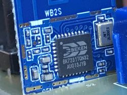
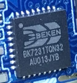
    I will present here the world's first WB2S/BK7231T WiFi module programming tutorial. BK7231T chip can be found in many smart home devices, and up to this day people used to say that one cannot create own firmware for it. Nothing could be more wrong - I will show you step by step how you can setup the necessary SDK, compile firmware, burn it by UART and then run UDP, TCP, HTTP and finally MQTT protocols on BK7231 chip! The tutorial will be very practical, because we will end up connecting our WB2S with the Home Assistant server via MQTT! Such a "release" of WB2S will allow us to create an open source , firmware, offering unlimited modification possibilities, transparent development process and independence from the manufacturer's servers.
    NOTE: In the text I assume that the reader knows the basics of C programming and IP protocols like UDP/TCP/HTTP/MQTT.

    A related topic about the XR809
    It is worth mentioning that I have already described another WiFi module - XR809 in a similar way:
    https://www.elektroda.pl/rtvforum/topic3806769.html#19447386
    The SDK in both cases is quite similar, e.g. the presence of the Lwip library is repeated, although e.g. this cool HTTP server with the XR809 SDK is not available here. Maybe I'll port it... but let's start with the basics.


    Preparation of hardware, connection of WB2S
    WB2S will only require two UART connections. So you will need the pins:
    - RX and TX (for programming)
    - 2RX and 2TX (for checking the output log on the UART from the chip)
    - of course, the GND and power supply, in this case I decided to connect to 5V before the LDO 3.3V
    NOTE: if we want to power from USB, we have to remove the large electrolytic capacitor in front of the LDO. It often has a size of 680uF, and such a large capacity connected to the USB will consume too much current at startup, which results in a USB device reset and problems with WB2S programming!
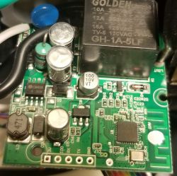
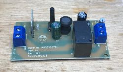
    For the demonstration, I used the NF101A relay:
    WB2S/BK7231 Tutorial - writing custom firmware - UDP/TCP/HTTP/MQTT
    WB2S/BK7231 Tutorial - writing custom firmware - UDP/TCP/HTTP/MQTT
    WB2S/BK7231 Tutorial - writing custom firmware - UDP/TCP/HTTP/MQTT
    But I also know other devices with WB2S inside, for example: SmartSwitch Tuya WL-SW01_16 16A WiFi .
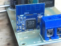
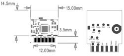
    Here you can see WB2S pin roles:
    WB2S/BK7231 Tutorial - writing custom firmware - UDP/TCP/HTTP/MQTT
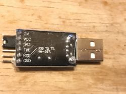
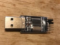
    To connect the UART to the computer you will need two adapters, here with the signal logic levels set to 3.3V. I am using USB TO TTL HW-597.
    WB2S/BK7231 Tutorial - writing custom firmware - UDP/TCP/HTTP/MQTT WB2S/BK7231 Tutorial - writing custom firmware - UDP/TCP/HTTP/MQTT
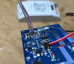
    Soldered wires to RX and TX (pads at the base of the module near the PCB) and the red cable to 5V (before LDO):
    WB2S/BK7231 Tutorial - writing custom firmware - UDP/TCP/HTTP/MQTT
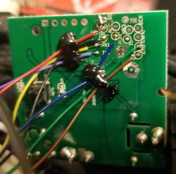
    Soldered 2RX and 2TX (tiny test pads on the "back" of the module):
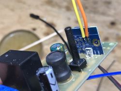
    WB2S/BK7231 Tutorial - writing custom firmware - UDP/TCP/HTTP/MQTT
    In order to secure the board and wires, I allowed myself to use hot glue temporarily:
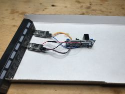
    WB2S/BK7231 Tutorial - writing custom firmware - UDP/TCP/HTTP/MQTT
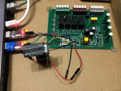
    Final work environment. You can see the necessary switch (programming needs) and two UART to USB adapters, one for programming, the other for reading the printf output:
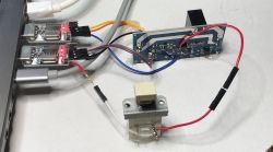
    WB2S/BK7231 Tutorial - writing custom firmware - UDP/TCP/HTTP/MQTT
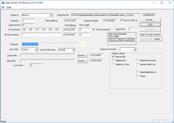
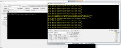
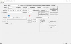
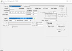
    I use BKwriter (bk_writer1.60) to program the firmware, the programming / reading procedure is simple. We start the activity in the program, then turn off the WB2S from the power supply (and only from the power supply) with the button, and after a while we restore the power supply. The program should continue running as in the screenshot:
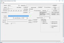
    WB2S/BK7231 Tutorial - writing custom firmware - UDP/TCP/HTTP/MQTT
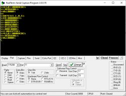
    I am using RealTerm to read information from UART as in the screenshot below:
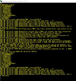
    WB2S/BK7231 Tutorial - writing custom firmware - UDP/TCP/HTTP/MQTT
    The work environment is ready! WB2S can be programmed.

    Configuration of the SDK and compiler
    I managed to achieve success with the load that is integrated with the Tuya environment (later we will try to "free" him from Tuya):
    https://github.com/tuya/tuya-iotos-embeded-sdk-wifi-ble-bk7231t
    First, we need to download the entire repository. This can be done via git (command line or SourceTree GUI client):
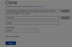
    WB2S/BK7231 Tutorial - writing custom firmware - UDP/TCP/HTTP/MQTT
    ... or via the browser (Code -> Download Zip button):
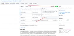
    WB2S/BK7231 Tutorial - writing custom firmware - UDP/TCP/HTTP/MQTT
    We unpack the package to, say, C: / bk7231 /:
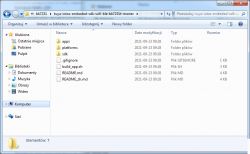
    WB2S/BK7231 Tutorial - writing custom firmware - UDP/TCP/HTTP/MQTT
    We get acquainted with the contents of the folder. Under the path \ bk7231 \ tuya-iotos-embeded-sdk-wifi-ble-bk7231t-master \ platforms \ bk7231t \ toolchain we have a nice surprise - toolchain is here, gcc-arm-none-eabi-4_9-2015q1 :
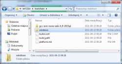
    WB2S/BK7231 Tutorial - writing custom firmware - UDP/TCP/HTTP/MQTT
    Next we need a linux environment to compile. I decided to emulate Linux on Windows via Cygwin. I have already described the installation of Cygwin here:
    https://www.elektroda.pl/rtvforum/viewtopic.php?p=19628606#19628606
    Installing Cygwin should include make and python 3.8.
    We run Cygwin and go to the SDK folder. We can list its contents:
    WB2S/BK7231 Tutorial - writing custom firmware - UDP/TCP/HTTP/MQTT
    The build_sh.sh script there contains everything we need.
    We run it through:
    Quote:

    ./build_app.sh apps / template_demo template_demo 1.0.0

    The arguments indicate which project to build from the apps folder:
    WB2S/BK7231 Tutorial - writing custom firmware - UDP/TCP/HTTP/MQTT
    It will take some time to compile:
    WB2S/BK7231 Tutorial - writing custom firmware - UDP/TCP/HTTP/MQTT
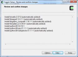
    If we get an error saying "python" was not found then we need to install Python. For me it is in version 3.8.10. We install it via the Cygwin installer (then it will only add the necessary packages):
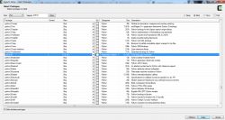
    WB2S/BK7231 Tutorial - writing custom firmware - UDP/TCP/HTTP/MQTT
    WB2S/BK7231 Tutorial - writing custom firmware - UDP/TCP/HTTP/MQTT
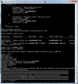
    Then the compilation should be successful:
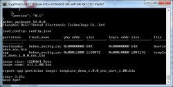
    WB2S/BK7231 Tutorial - writing custom firmware - UDP/TCP/HTTP/MQTT
    WB2S/BK7231 Tutorial - writing custom firmware - UDP/TCP/HTTP/MQTT
    The results are in apps \ template_demo \ output \ 1.0.0:
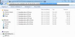
    WB2S/BK7231 Tutorial - writing custom firmware - UDP/TCP/HTTP/MQTT
    We use a file for uploading template_demo_UA_1.0.0 but that's in a moment. UA may suggest UART in its name.

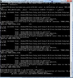
    Compile errors related to \ r (carriage return)
    If you still have problems running the build (build_app.sh), and these problems are related to the end-of-line standard (\ n and \ r), then the git client is probably causing the problem.
    The git client automatically converts the nextline characters to standard on your platform, but if you are using Windows, git will convert them to Windows standard, when Cygwin expects a linux standard, which will result in an error like this:
    WB2S/BK7231 Tutorial - writing custom firmware - UDP/TCP/HTTP/MQTT
    It is best to fix it in the git command line - turn off the automatic CRLF conversion and download the repository again - git config --global core.autocrlf false :
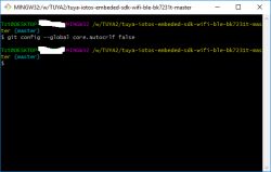
    WB2S/BK7231 Tutorial - writing custom firmware - UDP/TCP/HTTP/MQTT
    You can also do it manually (e.g. via Notepad ++, Edit-> EOL Conversion tab).

    The first hello world
    Compilation is already working, but we still need to somehow verify that we can actually edit these projects meaningfully and that the entire build is going well.
    I suggest adding a printf somewhere, let's say the famous "Hello world".
    This can be done in apps / template_demo / src / tuya_device.c in pre_device_init:
    WB2S/BK7231 Tutorial - writing custom firmware - UDP/TCP/HTTP/MQTT
    We're compiling, it's time to upload the firmware.

    The first load of the load
    You will need the bk_writer1.60.exe program, which I attach to the topic.
    The file that we will upload is template_demo_UA_1.0.0 (the file template_demo_1.0.0.bin will not work, BK will not start then). We choose it through "Browse" and click "Program".
    We choose the appropriate COM port in the program.
    Then turn off and on again the power supply from the module (but without removing the USB UART adapter from the computer port).
    For me, this is the large button that cuts off the + 5V connected to the 3.3V LDO input.
    The erasing of the old firmware will begin:
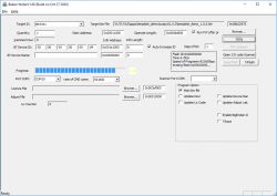
    WB2S/BK7231 Tutorial - writing custom firmware - UDP/TCP/HTTP/MQTT
    And then uploading a new one:
    WB2S/BK7231 Tutorial - writing custom firmware - UDP/TCP/HTTP/MQTT
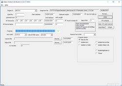
    Done, after 18 seconds:
    WB2S/BK7231 Tutorial - writing custom firmware - UDP/TCP/HTTP/MQTT
    After restarting the device, our message appears:
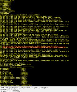
    WB2S/BK7231 Tutorial - writing custom firmware - UDP/TCP/HTTP/MQTT
    Then the WB2S will automatically run the uploaded firmware.

    Blink LED + Timers
    Each tutorial usually starts with a flashing LED, so we'll cover that here too. We will flash the diode through a timer that starts every second. We will make all modifications in tuya_device.c .
    First you have to connect somewhere - I suggest device_init, this function is performed at device startup:
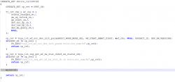
    WB2S/BK7231 Tutorial - writing custom firmware - UDP/TCP/HTTP/MQTT
    We create the myInit function ourselves. You need to initialize the state of the pins there and start the Timer:
    Code: c
    Log in, to see the code

    bk_gpio_config_output - sets the given pin to output mode
    bk_gpio_output - sets the value for the output of the given pin
    rtos_init_timer - creates a timer (the function will be automatically called from time to time)
    rtos_start_timer - the timer starts
    We just need to know which pin is which - where is GPIO24?
    GPIO24 corresponds to P24, and the locations of P24 will be known from the WB2S catalog note:
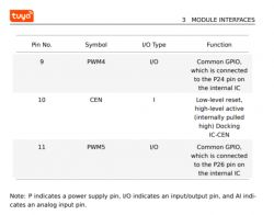
    WB2S/BK7231 Tutorial - writing custom firmware - UDP/TCP/HTTP/MQTT
    PWM4 is P24 or GPIO24, PWM5 is P26 or GPIO26.
    NOTE: on some ESP modules the GPIO numbers differ from the pin outputs of the system, it probably is not the case here!
    The state of the pins has also been changed and can additionally print something on the UART as part of the test:
    Code: c
    Log in, to see the code

    NOTE: the relay control (MY_RELAY) will not work if you power the module from an external 3.3V source because the relay is powered from the 5V line (before the LDO).
    Result:
    [movie: 7d040c325f] https://filmy.elektroda.pl/14_1638181056.mp4 [/ movie: 7d040c325f]
    The countdown on UART also works:
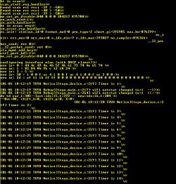
    WB2S/BK7231 Tutorial - writing custom firmware - UDP/TCP/HTTP/MQTT

    Connecting to a WiFi network
    It's time to connect to the WiFi network using its SSID and password. Unfortunately, we will provide the password in plain text - so far we are not making the code more complicated. After connection, you also need to use DHCP to get the IP address assigned dynamically, but most do BK for us. Here's the finished feature:
    Code: c
    Log in, to see the code

    In order for it to compile, we also need to attach one additional header:
    Code: c
    Log in, to see the code

    We call this function e.g. from device_init.
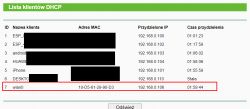
    We can check on the router if the device is connected:
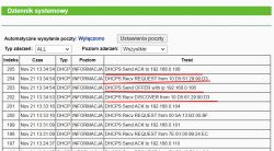
    WB2S/BK7231 Tutorial - writing custom firmware - UDP/TCP/HTTP/MQTT
    WB2S/BK7231 Tutorial - writing custom firmware - UDP/TCP/HTTP/MQTT
    We initially check the communication with the ping command. We can use the -t switch to ping non-stop, not just a few times.
    WB2S/BK7231 Tutorial - writing custom firmware - UDP/TCP/HTTP/MQTT
    I recommend that you disconnect the power of the WB2S while pinging and check if it loses its connection - this is to verify whether we are actually pinging our device, or maybe something else.
    Interesting fact: it is also worth knowing that there is a more advanced structure that allows you to connect to WiFi, you can also enter, for example, BSSID:
    Code: c
    Log in, to see the code

    But I'm just covering the basics here, so for now it's time to move on to sending packets over the network.

    UDP server
    It's time for something more ambitious and allowing communication on the Internet. UDP server. We start with UDP, because UDP is simpler, it is a connectionless protocol that does not guarantee that the packet will reach its destination. The package is sent once and if it is lost, we will not even know about it. The connection protocol (and it offers retransmission) is TCP, which we'll cover later.
    UDP support will be in thread. The recv command will block the thread from executing until it receives the packet. This solution is in contrast to "non-blocking" sockets, but we don't use them here.
    Code: c
    Log in, to see the code

    Sockets on WB2S look like on Linux, so you can follow the examples of Linux (and actually also from winsock). For this reason, I will not describe here how 'bind', 'recv', 'recvfrom', 'select', etc. works. Everything is standard.
    But let's not forget the headers, here are different than on other platforms:
    Code: c
    Log in, to see the code

    Yes, sockets also come from LWIP.
    For example, we create a socket like this:
    Code: c
    Log in, to see the code

    On the basis of this, you can create a function:
    Code: c
    Log in, to see the code

    Now all you have to do is send a UDP packet to that server somehow ... to test it.
    For this purpose, I have prepared a program that sends the package in C # (on the Windows platform):
    Code: c
    Log in, to see the code

    Time for a test. Does UDP communication work?
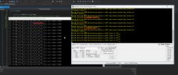
    WB2S/BK7231 Tutorial - writing custom firmware - UDP/TCP/HTTP/MQTT
    Works as you can see on both sides (WB2S and desktop application).


    TCP server
    We have already launched UDP, but UDP is not suitable for more serious applications because it does not have a reliability layer, it does not support automatic packet retransmission. Of course, we can implement something like this on UDP, but why?
    That's what TCP is for.
    TCP allows you to create a permanent connection with the client, separately we have the act of connection, data transfer, and connection closure.
    Therefore, with TCP, each client will receive its own thread, which will run until the connection is broken.
    Let's start by creating a TCP server thread:
    Code: c
    Log in, to see the code

    Now, the main server thread.
    Code: c
    Log in, to see the code

    When the TCP connection is established, a new client service thread is created - the tcp_client_thread function. The socket handle is passed to it as a parameter. This is needed because the recv and select functions are blocking here (blocking code execution until they receive something).
    Client handler function:
    Code: c
    Log in, to see the code

    Of course, you can use recv and send multiple times in this function. Len less than or equal to 0 will inform us about breaking the connection.
    I also had to add auxiliary functions to the code, e.g. defining tcp_server_log, if so, I put the full code as an attachment at the end of the topic.
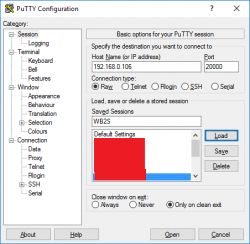
    On the computer side, you can use Putty in Raw mode. The computer will connect to the server and send it what we type in the console.
    WB2S/BK7231 Tutorial - writing custom firmware - UDP/TCP/HTTP/MQTT
    Let's check if TCP works now:
    WB2S/BK7231 Tutorial - writing custom firmware - UDP/TCP/HTTP/MQTT
    It works the most, but you can see that I lost the 0 character somewhere (byte zero, not in ASCII), as a result of which "bushes" entered the received message. This is not a problem, we can either send these 0 in the packet, or artificially add them to the end after receiving the packet (buff [len] = 0).

    HTTP Server
    We also have the HTTP server ready, it is in the lwIP [/ b] library. Only this time we need to add its sources to the [b] makefile [/ b] so that the compiler knows that its code should be included in the project.
    HTTP server code is in [b]httpd.c
    and fs.c from platforms/bk7231t/bk7231t_os/beken378/func/lwip_intf/lwip-2.0.2/src/apps/httpd.
    Let's add them to application.mk:
    WB2S/BK7231 Tutorial - writing custom firmware - UDP/TCP/HTTP/MQTT
    If we don't add them, we'll get linker errors when compiling, for example:
    Quote:

    W:\TUYA3\platforms\bk7231t\bk7231t_os/../../../apps/my_http_server_demo/src/tuya_device.c:736: undefined reference to `httpd_init'

    Now we still need to start the server. For now, let's just call httpd_init in device_init:
    Code: c
    Log in, to see the code

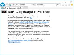
    And that's enough - the WB2S web page is working now!
    WB2S/BK7231 Tutorial - writing custom firmware - UDP/TCP/HTTP/MQTT

    HTTP Server - simple web page
    The HTTP server from the library that is available in this SDK is built in a fairly static way and it will probably need to be redone, but it is still worth presenting here how to add a new file.
    The contents of the file platforms/bk7231t/bk7231t_os/beken378/func/lwip_intf/lwip-2.0.2/src/apps/httpd/fsdata.c
    I will quote a fragment of it here:
    Code: c
    Log in, to see the code

    Here we have hard-typed HTTP responses to a GET request with a given path. Here, such an answer is together with the contents of the file. Moreover, these responses are written in hex, not the normal text (char) that we can easily read. Of course, after converting the hex value to an ASCII character, we can read what is what.
    You can easily "translate" such an array of bytes into ascii characters, just paste them into C code and print or preview in a debugger e.g. in Visual Studio, like this:
    Code: c
    Log in, to see the code

    So, let's take a look at the full value from one of the buffers:
    Code: html
    Log in, to see the code

    First there is the name of the file (terminated by a byte zero). The HTTP response starts with the "HTTP / 1.0" header, and the HTML response starts with <html>. This server here doesn't even "know" what is what, it treats it as one string.
    We have a bit lower:
    Code: c
    Log in, to see the code

    Here the structures representing the files are defined. Those cryptic "12" are the length of the filename at the beginning of the buffer. For example, the length of "/index.html" is 12 (11 characters + 1 NULL terminating character). It's a bit inconvenient that you have to manually enter this value into the code ... Let's see what makes up the fsdata_file structure:
    Code: c
    Log in, to see the code

    Here we have a pointer to the next file (one-way list), a pointer to the name of the file (a string terminated with a byte zero character) and a pointer to its data (the body of the response to the GET, along with the HTTP header and the content of the file). Additionally, the length and field for the flags. Checksum support is disabled at this point.
    The first file in turn is specified by this line:
    
    #define FS_ROOT file__mytest_html
    

    Can I add a file here? Absolutely. First, let's create its content, for example it could be:
    Code: html
    Log in, to see the code

    Then let's convert it into hexes after the decimal point. This can be done ... by a separate C program that I ran on windows:
    Code: c
    Log in, to see the code

    You still need to analogically convert its file name - say, "tst.html" - also to hex codes and add a 0 character ending the string, and then you can create an analogous table with the response to his GET request, also in fsdata.c [/ b].
    You also need to create an additional instance of the [b] fsdata_file [/ b] structure separately and attach it to a one-way list.
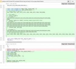
    Below is the full 'diff' of what I wrote about [b]fsdata.c
    :
    WB2S/BK7231 Tutorial - writing custom firmware - UDP/TCP/HTTP/MQTT
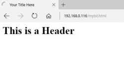
    It works, as you can see below:
    WB2S/BK7231 Tutorial - writing custom firmware - UDP/TCP/HTTP/MQTT

    MQTT support - necessary fix
    It's time to move on to MQTT, a protocol that will provide us with, among others Home Assistant compatible.
    Unfortunately, the MQTT library available in the discussed SDK is not complete. It lacks the implementation of MQTT client authorization. We have to implement it ourselves.
    MQTT also comes from the lwip-2.0.2 library. The implementation is in platforms\bk7231t\bk7231t_os\beken378\func\lwip_intf\lwip-2.0.2\src\apps\mqtt\mqtt.c

    There is a mqtt_client_connect function to be fixed, because it does not include the password and username in the package being built, so MQTT will only work in no login mode.
    How do I know about this?
    I compared the packages sent by WB2S (with the library unchanged) with the packages sent by the MQTT testing tool (MQTT Explorer). I used Wireshark to preview the packages. Below are the results:
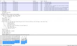
    WB2S/BK7231 Tutorial - writing custom firmware - UDP/TCP/HTTP/MQTT
    (by the way - Wireshark decodes MQTT packets automatically, a very useful feature!)
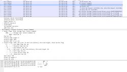
    WB2S/BK7231 Tutorial - writing custom firmware - UDP/TCP/HTTP/MQTT
    You can see what's missing, right?
    Below I am attaching screenshots of my corrections, I will give you all for download at the end of the topic:
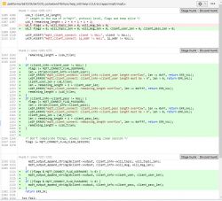
    WB2S/BK7231 Tutorial - writing custom firmware - UDP/TCP/HTTP/MQTT
    Additionally, you have to add mqtt.c to compilation in application.mk:
    WB2S/BK7231 Tutorial - writing custom firmware - UDP/TCP/HTTP/MQTT
    You can try compiling, but that won't work yet:
    
    ../../../sdk/lib/\libtuya_iot.a(libemqtt.c.o): In function `mqtt_disconnect':
    /root/workspace_temp/EmbedSDKs/ty_iot_wf_bt_sdk_bk/ty_iot_wf_bt_sdk_bk/sdk/mid_mqtt/src/libemqtt.c:315: multiple definition of `mqtt_disconnect'
    Debug/obj/mqtt.o:W:\TUYA3\platforms\bk7231t\bk7231t_os/beken378/func/lwip_intf/lwip-2.0.2/src/apps/mqtt/mqtt.c:1346: first defined here
    collect2.exe: error: ld returned 1 exit status
    

    It turns out that there is already a function in libtuya_iot.a called mqtt_disconnect. We cannot have a second name the same, we need to rename the one from mqtt.c:
    WB2S/BK7231 Tutorial - writing custom firmware - UDP/TCP/HTTP/MQTT
    MQTT library is ready, it's time to use it in practice.

    MQTT support - step by step
    Basic information about MQTT is in the readme file, but I'll cover it here anyway. MQTT service comes down to the following steps:
    Step 1: Include the header:
    Code: c
    Log in, to see the code

    Step 2: Client allocation.
    Static method:
    Code: c
    Log in, to see the code

    Dynamic method:
    Code: c
    Log in, to see the code

    Step 3: Establishing a connection. The mqtt_connect_client_info_t also includes the username, password, etc., as needed.
    Code: c
    Log in, to see the code

    NOTE: You can use mqtt_client_is_connected (client) to check the client status.
    Step 4. Implementation of connection state handling (in the form of callback). This is done because the connection may take some time and we don't want to block the rest of our code from being executed (as in the case of blocking sockets).
    Code: c
    Log in, to see the code


    Step 5: Implementation of data receiving callbacks (so-called in MQTT "publish"). In MQTT "publish" can be both ways, either from us or to us:

    Code: c
    Log in, to see the code


    Step 6: Since we have a reception, we also need to be able to transmit - the publish send implementation:

    Code: c
    Log in, to see the code

    NOTE: We can enter anything into the publish content, but for example Home Assistant uses the JSON format there.
    Step 7: Disconnect / End MQTT Operation:
    Code: c
    Log in, to see the code


    MQTT support - a practical example - compatibility with Home Assistant
    Now let's use the knowledge gathered here and prepare a program that will report its condition through MQTT. For example, we can report temperature measurements in this way. Of course, we will generate the measurement itself randomly, this example does not cover anything other than MQTT.
    You will also need a server for the demonstration - I will use the Home Assistant server here, prepared according to my tutorial:
    https://www.elektroda.pl/rtvforum/topic3777098.html
    We need the MQTT username and password from our server. We take them from the settings of the Mosquitto MQTT broker:
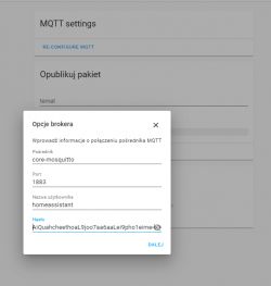
    WB2S/BK7231 Tutorial - writing custom firmware - UDP/TCP/HTTP/MQTT
    In the code, they are represented by the mqtt_connect_client_info_t structure. Let's initialize it with the appropriate fields:
    Code: c
    Log in, to see the code

    The server IP is a bit different. Here is also the setting of callbacks:
    Code: c
    Log in, to see the code

    Now the content of the less important, auxiliary functions:
    Code: c
    Log in, to see the code

    The most important is the function that performs publish, that is sending the device state via MQTT.
    For Home Assistant, it contains temperature information in the form of JSON:
    
    {\"temperature\": \"45.5\"}
    

    In the example below, I create a temperature value from a loop counter using the sine function so that the same values ​​come out repeatedly. We will see it in the graph from the Home Assistant.
    If publish fails, I retry the MQTT connection.
    Code: c
    Log in, to see the code

    The second argument in mqtt_publish is the so-called 'topic'. It should align with what we're listening to in HA.
    We have to call Publish ourselves - e.g. from a timer:
    Code: c
    Log in, to see the code

    NOTE: The security issue of calling this library's functions from a thread other than the one that was started has not been fully checked by me.
    On the Home Assistant side, we need to add an entry to /config/configuration.yaml. We inform the server what type of publish to listen to and how to process it:
    
    sensor:
      - platform: mqtt
        name: "WB2S"
        state_topic: "wb2s"
        qos: 0
        unit_of_measurement: "ºC"
        value_template: "{{ value_json.temperature }}"  
    

    It is important that the names (name and topic) match, and that the value obtained from JSON ("temperature") has a real name.
    If you have several devices, you can give them different names and have different, separate graphs.
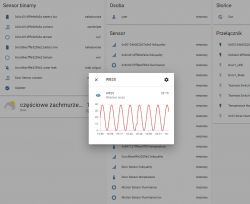
    As a result, in Home Assistant we get the following chart:
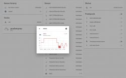
    WB2S/BK7231 Tutorial - writing custom firmware - UDP/TCP/HTTP/MQTT
    WB2S/BK7231 Tutorial - writing custom firmware - UDP/TCP/HTTP/MQTT
    The full code of the MQTT example is also included in the appendices.

    Download modified SDK and my examples
    Below I put the SDK modified by me along with the projects of each of the examples in the app folder. NOTE - I cut the toolchain from the SDK because it took up over 600MB, so you have to download it from the repo separately ...
    wb2s-updat...130-v1.zip Download (20.78 MB)Points: 0.5 for user
    bk_writer1...210523.zip Download (302.64 kB)

    Things left to do
    There are a few things left to do here. Below is a list, in a random order:
    - this HTTP server from the used SDK for WB2S is weak, either I will convert it or I am sporting the server with the XR809 SDK (which I have already launched)
    - I did not work out the save to the settings memory so that WB2S remembers what WiFi connected to, but this is not a problem
    - one could try to "free" this WB2S a bit more from the Tuya environment because at the moment it is in the background to some extent. You need to clean the tuya_device file from unnecessary function calls and maybe even experiment with bypassing libraries (but in fact, the bootloader will be useful for us ... we do not want to program it later via JTAG, which is also possible, if I remember correctly)
    - the world does not live by WB2S alone, you should check what with WB3S and similar

    Open source firmware project for WB2S and similar
    Most of the necessary mechanisms needed to prepare universal, open programming (similar to eg Tasmota) for these systems are already operational.
    Therefore, I am starting a project with the temporary name OpenWB2S. The project will be developed in parallel with the OpenXR809 project, which will work similarly, but on the XR809 chip, details here: [url = https: //www.elektroda.pl/rtvforum/topic3806769.html#19447386] Own open firmware for XR809 compatible with Tasmota HTTP / Home Assistant [/url].
    Project support - interested parties can support the project through:
    - testing (in some time I will create a github repository for both projects)
    - collecting information in what devices are what modules (you can send photos, etc., even in this topic. I know about the list https://templates.blakadder.com/)
    - paypal donation:
    https://paypal.me/openshwprojects

    (There are some of these different devices and I want to test as many of them as possible, moreover, I have already put a lot of teardown at https://www.elektroda.pl/rtvforum/forum507.html, the funds will go to the purchase of more devices)
    - if you have, for example, WB2S modules that you have left after replacing with ESP12F or damaged smart devices, etc., I can accept them for testing (contact PW)
    There are many more modules similar to WB2S, for example there is WB3S and I also have to test it soon ...

    Summary
    This is the second seemingly closed WiFi module that I was able to work out. It was similar with the XR809 - also no one knew that it could be run on independent software. It was similar here with WB2S.
    Now I plan to develop my software for both of these modules and soon I will also set up github repositories for both projects. The goal will be to make a Tasmota equivalent with MQTT support. It is difficult for me to say how long it will take, and it also depends on the response and interest, but I can already reveal that the next topic I want to present on the forum will be a detailed MQTT tutorial, but this time on the XR809.
    The topic will be updated and corrected.[/b][/b][/b][/b]

    Cool? Ranking DIY
    About Author
    p.kaczmarek2
    Moderator Smart Home
    Offline 
    p.kaczmarek2 wrote 4836 posts with rating 5167, helped 235 times. Been with us since 2014 year.
  • #2
    blakadder
    Level 6  
    I have a bunch of Tuya modules for you ;)

    I'd also recommend to broaden the project name since the same Beken chip is used in other modules and in non tuya devices
  • #3
    freedomlives
    Level 1  
    I just received some smart plugs which unfortunately have this module instead of ESP. Will try flashing one per your instructions.
  • #4
    p.kaczmarek2
    Moderator Smart Home
    blakadder wrote:
    I have a bunch of Tuya modules for you ;)


    That's great, if you're interested in donating Tuya modules for testing then please PM me.

    I also know that some of WB modules might be pin compatible with ESP12F modules, so.... so I could use ESP12F breakout to create my own WB dev board.

    blakadder wrote:

    I'd also recommend to broaden the project name since the same Beken chip is used in other modules and in non tuya devices


    I will. I know that there is a lot of modules with exactly the same chip - BK7231T - including WB2S, WB2L, WB3S, WB3L, WB3S-IPEX, WBLC5, WB8P, WBLC9, etc..
    It's just that I don't like the today-common approach of " first advertise, then underdeliver ", and with such a development in the uncharted territory it's difficult to say with a fair amount of certainty that my approach will work out for all of them as well.

    Keep in mind that right now I am using UART bootloader and not just burning my firmware with ST-link over the blank BK chip.

    Still, I will try to check out ALL OF THEM. I just need to get them somehow.

    But don't worry, even if approach based on tuya-iotos-embeded-sdk-wifi-ble-bk7231t SDK fails, then I always have a backup option in form of ALios SDK, which I think could also easily support those modules, but this time with ST-link programmer requirement.

    PS: BKwriter also supports BK3435, BK3266, BK3432, BK3288 and BK3633, but they don't seem as much popular as BK7231T.


    EDIT: I am attaching diff/patch files for MQTT fix necessary for authorization support:
  • #5
    ex-or
    Level 28  
    p.kaczmarek2 wrote:
    It's a bit inconvenient that you have to manually enter this value into the code ...

    There's no need to. Somewhere in the lwip directories there should be a program fsgen (or something like that) that creates this filesystem from the indicated files.
  • #6
    p.kaczmarek2
    Moderator Smart Home
    ex-or wrote:
    fsgen (or something like that).

    Indeed, there is makefsdata. I think I underestimated the authors of this library a bit.
    WB2S/BK7231 Tutorial - writing custom firmware - UDP/TCP/HTTP/MQTT
  • #7
    DrTFav
    Level 2  
    Great work! I look forward to seeing more on the Beken chips! I was able to use inspiration from your XR809 project to take control of a water leak sensor that uses Tuya serial protocol, MQTT HA discovery, and MQTT reporting of the status https://github.com/tony-fav/FavTuyaXR3/blob/master/project/at_demo/main.c Tuya protocol would be my first goal to implement as many many devices with the Beken chips use the Tuya Serial protocol to control a secondary chip.
  • #8
    p.kaczmarek2
    Moderator Smart Home
    @DrTFav it's nice to see more people using my tutorial. I also worked on Tuya protocol several times, for example here:
    https://www.elektroda.com/rtvforum/topic3819498.html
    I also found a smart touch switch with a different protocol, a text-based one with "AT-UPDATE" like strings:
    https://www.elektroda.pl/rtvforum/topic3812227.html

    also:
    Quote:

    I tried disabling both the web server and at_cmd code and the whole thing just seemed to break/stop working. Not sure what that's about.

    I see you're doing everything in main() loop instead of using interrupts. Maybe the web server thread is the only place now where IP packets polling is called (assuming they are using poll for that).

    Where can I buy the sensor you have?
  • #9
    DrTFav
    Level 2  
    I bought mine locally from a USA hardware store, but there are some of the same form factor on AliX. No guarantee of what's inside though, of course.
  • #10
    chemik_16
    Level 25  
    well, I can see that you have pushed the topic forward nicely :) congratulations.
    The bk7231 is a very nice chip, much more interesting than the esp8266, it competes calmly with the esp32 ;)
    I am finishing the renovation and I am also joining the programming of this product, I have 10 tuya sockets, ultimately I want to put them on
    MQTT (switch, current and voltage meter, led) + BLE gate
    maybe the tasmote can be ported too

    but as a priority - cut it off from any communication with the outside world ;)
  • #11
    khoam
    Level 42  
    chemik_16 wrote:
    maybe the tasmote can be ported too

    Tasmota's code is entirely based on the Arduino Core, so the latter would have to be ported in the first place.
  • #12
    DrTFav
    Level 2  
    p.kaczmarek2 wrote:
    @DrTFav it's nice to see more people using my tutorial. I also worked on Tuya protocol several times, for example here:
    https://www.elektroda.com/rtvforum/topic3819498.html
    I also found a smart touch switch with a different protocol, a text-based one with "AT-UPDATE" like strings:
    https://www.elektroda.pl/rtvforum/topic3812227.html

    also:
    Quote:

    I tried disabling both the web server and at_cmd code and the whole thing just seemed to break/stop working. Not sure what that's about.

    I see you're doing everything in main() loop instead of using interrupts. Maybe the web server thread is the only place now where IP packets polling is called (assuming they are using poll for that).

    Where can I buy the sensor you have?


    I am confused by your link (https://www.elektroda.com/rtvforum/topic3819498.html). The Tuya protocol is well known and they make it public (https://developer.tuya.com/en/docs/iot/tuya-cloud-universal-serial-port-access-protocol?id=K9hhi0xxtn9cb). It is not something that has to be reverse engineered in the way you are attempting there. Both Tasmota and ESPHome have methods for dealing with it.
  • #13
    p.kaczmarek2
    Moderator Smart Home
    DrTFav wrote:
    I am confused by your link (https://www.elektroda.com/rtvforum/topic3819498.html).

    I know that Tasmota has Tuya protocol support, I used Tasmota with this protocol for example here:
    https://www.elektroda.pl/rtvforum/topic3825966.html
    I even referenced this link: https://tasmota.github.io/docs/TuyaMCU/ in the above topic.
    You should treat my "reverse engineering" topic rather as a learning exercise, an example of how to approach unknown UART protocol for beginners, and not as the real attempt of reversing it once again while it's already public.

    PS: It's just that I like writing a simple step-by-step guides for beginners (because I knew and know many beginners and I know how they think and what they need), I do the same for non-Tuya topics as well. Example: https://www.elektroda.pl/rtvforum/topic3742912.html
  • #14
    The_Digital_1
    Level 2  
    @p.kaczmarek2 Is it possible some devices may be fuse locked and are unable to program? I have some HBN BNC-60/UT152T plug switches that use the WB2S module, with the BK7231 chip. When i use the Bkwriter tool it fails to flash or erase. I don't believe it is my USB to serial adapter as i have scoped the signals and they look clean. Upon plugging in the VCC to the chip the BKwriter immediately fails. Looking at the decode of the RX on the programing UART i get the following: 0xF5 0xFD 0x40 0xFF 0xF7 0xE3 0xF5 0xFD 0x40 0xFF 0xF5 0xFD 0x40 0xFF

    Dodano po 18 [minuty]:

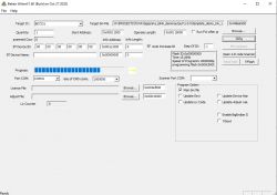
    @p.kaczmarek2 actually ignore that RX dump, its probably wrong, that was when i was at the wrong baud rate. Setting baud rate to 115200 like you did it seems to start erasing flash but gets stuck. See attached. FYI i can perform a read operation successfully, so again i feel like the HW setup is right. WB2S/BK7231 Tutorial - writing custom firmware - UDP/TCP/HTTP/MQTT

    Dodano po 4 [minuty]:

    Looks like it performed a partial erase, as the device now no longer boots up and it just keeps printing the attached on TX2. WB2S/BK7231 Tutorial - writing custom firmware - UDP/TCP/HTTP/MQTT
  • #15
    ryanpavlik
    Level 5  
    Have you managed to read-out any of the original Tuya firmware with bk_writer? I tried on one of mine briefly but it just appeared to time-out. (I'm trying to reverse-engineer the UART protocol used by bk_writer, and while digging into bk_writer itself is finding some interesting information, it would be simpler to just sniff the tool in operation :D )

    Many devices with this have a "CEN" pin broken out - my hunch is that it's "chip enable" aka reset - pull to ground causes something that looks like a reset, anyway.

    BTW: UA means "User Area". It's one of the firmwares you'd upload to Tuya. QIO is the "production area" firmware. The tool seems to have preferential treatment for 115200, even though the Tuya docs say to use 921600.

    It's a shame you can't apparently buy this chip outside of the Tuya ecosystem (or maybe outside of China) - it does look pretty promising.
  • #16
    ryanpavlik
    Level 5  
    Oops... I had gotten pretty far reversing the Beken writer tool, when I tried a few different search terms and found this Python implementation, apparently from the company itself, just not on its organizational GitHub account: https://github.com/tiancj/hid_download_py/blob/master/bkutils/boot_protocol.py

    Parts of it look like almost a direct translation of the c++ code, I recognize the parameters counts and values...

    Well, better to find this late than never!

    The board I have doesn't appear to be responding to the tool, however: is there some kind of lock that would stop readout? I do have other bk7231 boards, I just had nice fly wires soldered to the first one already...
  • #17
    p.kaczmarek2
    Moderator Smart Home
    The_Digital_1 wrote:
    When i use the Bkwriter tool it fails to flash or erase.

    I don't know if BK chip can be locked, but I remember having issues with programming XR809 with low quality USB to UART bridge. Could you try using the same one I have?
    If you are powering your module from USB port, are you sure that you removed the big bulk capacitor, because large capacitances cannot be connected to VUSB directly?
    The_Digital_1 wrote:
    Upon plugging in the VCC to the chip the BKwriter immediately fails

    is it failing with "usb device unplugged" sound from Windows?

    The_Digital_1 wrote:
    BNC-60/UT152T

    Something from this series? https://www.bn-link.com/products/bn-link-extr...-switches-for-purchase-new-kit-bnc-60-u116r-5
    I will try to find it with shipping to Poland, but I buy devices with EU plugs...

    ryanpavlik wrote:
    Have you managed to read-out any of the original Tuya firmware with bk_writer?

    Yes, no problems here. I also remember that I have reflashed BK with original firmware after flashing it with my own and it worked as well. I also noticed that the original firmware (just like the generated one) is encrypted and one cannot, for example, see string constants.


    ryanpavlik wrote:
    I'm trying to reverse-engineer the UART protocol used by bk_writer, and while digging into bk_writer itself is finding some interesting information, it would be simpler to just sniff the tool in operation :D )

    IDA Pro might be helpful here, it can also generate pseudo C code

    ryanpavlik wrote:
    https://github.com/tiancj/hid_download_py/blob/master/bkutils/boot_protocol.py

    That's a great find, I haven't seen it before. Still, why do you need a source code for that, what's your point of reversing the UART programming protocol for BK?


    I can't replicate problems you both have, can you tell me which devices are you using for testing right now? I will try programming WB3S later and see how it goes. So far, I haven't found any problematic Beken chips.
  • #18
    ryanpavlik
    Level 5  
    Well, before I found the Python script, my goal was partially to write an open source Python replacement for the bk writer app 🤣. It was also good practice with Ghidra and with x86 assembly, so not all was in vain. It was actually nice to see that what I had learned matched the Python port very closely.

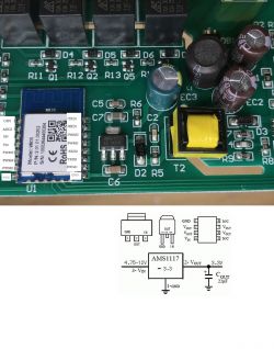
    The device I have wired up right now was sold as a Feit Electric outdoor smart plug, model Plug/Wifi/wp (fccid not at hand), does not have a module, and was clearly originally an esp8266.

    WB2S/BK7231 Tutorial - writing custom firmware - UDP/TCP/HTTP/MQTT

    WB2S/BK7231 Tutorial - writing custom firmware - UDP/TCP/HTTP/MQTT

    I also have an RGB bulb with a WB8P that I'll have to wire up and play with, haven't done that yet. Pretty sure I have at least one thing with a WB2S here that I just haven't opened (smart outlet), I'll dig around and wire that up too.
  • #19
    p.kaczmarek2
    Moderator Smart Home
    ryanpavlik wrote:

    The board I have doesn't appear to be responding to the tool, however: is there some kind of lock that would stop readout?

    Are you able to receive the debug log output print on the second UART?

    There is a large bulk capacitor on your board photo. Is it at VIN side of 1117-3.3V? If you want to be able to power board from 5V USB, then this capacitor has to be removed. Otherwise, when you disconnect and reconnect power for programming, too big capacitance-->too big incrush current will cause USB port to reset and disconnect USB to UART dongle.

    Also check if there is anything extra connected on UART lines, like a status diode or something, it happened to me once in case of TYWE3S, but I don't think it's the case here

    Btw: I just remembered that I have one more WB3S device! The four relays controller, the one I reviewed here:
    https://www.elektroda.pl/rtvforum/topic3822484.html
    I will need now to remember where I put that, and I will also check if I'm able to flash it.
  • #20
    ryanpavlik
    Level 5  
    Hmm, same "no response" results with the WB8P. I now suspect a more general problem: do you upload firmware through rx1/tx1 or rx2/tx2? If not that, maybe it's my uart adapter, cp2102 based. I ordered some ch340 ones that will be here next week. I might try my bus pirate if I can remember how to use it.

    I also tried some different power up vs click "read" timing: since I saw with the protocol analyzer that it's sending "reboot\r\n" then a basic minimal message repeatedly, I even tried plugging the board power back in after clicking read. I did pull a capacitor on the WB8P based device to get easier access to the back test points, I didn't trace the circuit out yet but I don't see the uart adapter dropping when I plug in the power.

    I need to assemble a second uart adapter here: the second one I used most recently is acting up and putting out 4.2v on the 3.3v line 😱 fortunately it didn't fry the tywe-3s in the nanoleaf-inspired wall art thing I last used it on.

    EDIT: OK, second uart displays stuff fine. I managed to dump the firmware from the WB8P by fiddling with the power cable. Think it was back-powering thru the uart lines or something, since sometimes it appeared to start booting when I **unplugged** the power. Very pleased I finally got it to work, though. Now I can start in on the software. Hoping to avoid using the Tuya base, especially since the toolchain and makefiles seem broken on Linux/WSL and only work on Windows. I know there are existing Arduino board packages that use FreeRTOS, so I'm hoping that the BK7231 FreeRTOS integration will let me bring up a more friendly environment that way. (arduino/platformio)
  • #21
    ryanpavlik
    Level 5  
    Tool chain update: it looks like "otafix" and "encrypt" are run on the binary to turn it into the uart compatible "ua" binary. On initial impression, otafix looks like it just pads the size? Encrypt is similarly pretty simple: it looks like it pads a bit then encrypts using DES (symmetric encryption!) with the key provided in the command line (and thus by the script). Since the key in the script was enough to let you build an image to install, I suspect it should also be enough to decrypt firmware dumps.

    I have also found this: https://github.com/tiancj/rtt_ota_tools which suggests there's a variety of encryption algorithms available, but it might depend on the bootloader that got flashed over SPI. (One of the official repos actually has two bootloader binaries, with and without encryption) Presumably something in the chip must know the encryption key, and the bootloader seems like a reasonable option.

    Do we know much about the HID-connected spi programmer for these chips? The previous Python repo I linked did have support for their protocol, but I don't know where to get one or even what IC is used since all photos show the connector side which has no chips, just connectors and passives.
  • #22
    p.kaczmarek2
    Moderator Smart Home
    ryanpavlik wrote:
    Hoping to avoid using the Tuya base, especially since the toolchain and makefiles seem broken on Linux/WSL and only work on Windows

    Please post error messages here, I will try to help.

    ryanpavlik wrote:
    . I managed to dump the firmware from the WB8P by fiddling with the power cable. Think it was back-powering thru the uart lines or something,

    are your UART logic levels not 3.3V? The IO pins might have a protection diodes to chip VDD, that's how many MCUs might work without connecting power to VDD pins, just to IOs. This is so called "trap for young players", as would Dave Jones say.

    Anyway, glad to hear it's working for you now!

    ryanpavlik wrote:

    Do we know much about the HID-connected spi programmer for these chips?

    In the XR809 topic I mentioned that Alios SDK prompts a ST-Link V2 dialog after a successfull compile and all SPI pins are available if you want to solder wires. I have ST-Link V2 at hand but I just didn't have time to try it.

    ryanpavlik wrote:

    I suspect it should also be enough to decrypt firmware dumps.

    The interesting thing to mention here is that the first WB2S module I tested retained it's WiFi configuration (with password) even after flashing it with blink. I mentioned it in XR809 topic. The WiFi stuff must be stored somewhere else. This is different than the ESP8266 case, where I was able to find my WiFi credentials in read firmware just by using simple text editor (so basically, throwing any tuya ESP smart device to trash might compromise your wifi network).

    Some time ago I had an idea... maybe I should create a VMware virtual machine image for (let's say) Linux with whole toolchain set up so people can get a quickstart with Beken chip easier? And just distribute the image. But still, one could say that people unable to setup SDK correctly wouldn't be able to contribute much anyway....


    p.kaczmarek2 wrote:

    Btw: I just remembered that I have one more WB3S device! The four relays controller, the one I reviewed here:
    https://www.elektroda.pl/rtvforum/topic3822484.html
    I will need now to remember where I put that, and I will also check if I'm able to flash it.

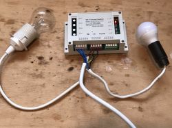
    I've found that 15 minutes ago, it was in the basement. I've setup a test stand for that and you know what, it work's like a charm.
    WB2S/BK7231 Tutorial - writing custom firmware - UDP/TCP/HTTP/MQTT
    WB2S/BK7231 Tutorial - writing custom firmware - UDP/TCP/HTTP/MQTT
    WB2S/BK7231 Tutorial - writing custom firmware - UDP/TCP/HTTP/MQTT
    WB2S/BK7231 Tutorial - writing custom firmware - UDP/TCP/HTTP/MQTT
    I am able to both flash new firmware and read the existing one (the Tuya one as well)

    Important notes:
    1. I am using USB to TTL HW597 dongles
    2. Each dongle has a jumper between 3.3V and VCC (select 3.3V logic levels)
    3. I am powering WB3S by extra wire connected to VBUS from USB soldered to dongle, and by any chance, NOT from "5V" pin on dongle, which is not a VBus, it's used only to select logic level
    4. I removed 470uF cap from board
    5. VBUS is obviously connected through button (from old TV) to input pin of 1117 3.3V

    See diagram:
    WB2S/BK7231 Tutorial - writing custom firmware - UDP/TCP/HTTP/MQTT

    Programming my blink... (with no changes at all)... and.. it's alive!


    You can hear relay clicking, both relay and LED here is on the same WB3S pin.
  • #23
    ryanpavlik
    Level 5  
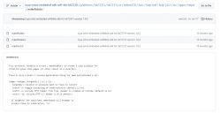
    Quick update: I have a CMake-based build (instead of bash and makefile) here: https://github.com/rpavlik/tuya-iotos-embeded-sdk-wifi-ble-bk7231t/tree/cmake Doesn't match perfectly yet, but I think it's close. It does complete, I haven't tried using the build it makes though. It should also be portable to the other bk7231 SDK repos.

    The UA file is "user area" but also UART. QIO is "as in spi flash qio" - the full image that you'd put on from the factory if not using uart there. UG is the "upgrade" OTA file for Tuya-driven upgrades.

    I think the IO voltage is 3.3 on my uart adapters. They aren't like yours, though. I have ordered ones like yours. I'm also not feeding "before the LDO" but rather sending 3.3v directly to the module's vcc/vbat pin.
  • #25
    MrTechGadget
    Level 2  
    So exciting to see this progress and continued activity. I'm very much looking forward to seeing this effort progress to something that is consumable by more people that really would like to free their devices from Tuya cloud!
  • #26
    p.kaczmarek2
    Moderator Smart Home
    @ryanpavlik by the way, have you seen that?
    https://www.elektroda.pl/rtvforum/topic3823834.html
    Having reversed UART programming protocol for Beken chips could be useful for development workflow automatization, something like "automatically flash firmware after next version is compiled", I know it seems like extra work to do but it's extremaly useful when you have to work on a code for a longer time.
    The resetting of module (disconnecting power and reconnecting it) could be done by DTR pin available on some UART bridges, or by MCP2221 IO pins (as in linked example)

    The_Digital_1 wrote:

    10$ for each and 10$ shipping for Poland? It's not the voltage nor standard we have here, but I would buy it anyway. The only issue is that Amazon doesn't seem to accept Paypal directly... I will think about it.

    MrTechGadget wrote:
    So exciting to see this progress and continued activity.!

    I will try to get a very basic but practical demo soon. It will be based on already mentioned relays module:
    WB2S/BK7231 Tutorial - writing custom firmware - UDP/TCP/HTTP/MQTT
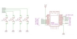
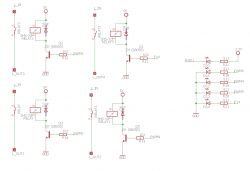
    Schematics (as drawn by me, several months earlier):
    WB2S/BK7231 Tutorial - writing custom firmware - UDP/TCP/HTTP/MQTT
    WB2S/BK7231 Tutorial - writing custom firmware - UDP/TCP/HTTP/MQTT
    WB2S/BK7231 Tutorial - writing custom firmware - UDP/TCP/HTTP/MQTT
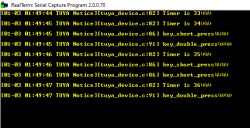
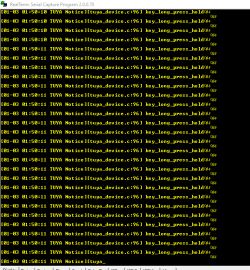
    Buttons are working (can detect click, double click and long held press):
    WB2S/BK7231 Tutorial - writing custom firmware - UDP/TCP/HTTP/MQTT
    WB2S/BK7231 Tutorial - writing custom firmware - UDP/TCP/HTTP/MQTT

    Most likely at first I will focus on MQTT stuff and on creating a flexible buttons/relays remaping backend in code, while the WiFi pass and the buttons configuration will be configurable only at compile time (so the first version will have to be recompiled by user in order to use), and then I will think about Tasmota-like HTTP configurator. The Tuya remnants also will have to be removed/disabled or replaced if possible (if it's possible to get mentioned non-tuya FreeRTOS working).
  • #27
    btsimonh
    Level 11  
    Hi All,

    I have been taking a look at the python based flasher.
    clone is in my repos (search btsimonh hid_download_py in github - sorry I'm not able to post links yet here.) - I will update it with my mods when I've completed my mods.

    (Update - updates on branch btsimonhmaster at github.com/btsimonh/hid_download_py/tree/btsimonhmaster - now has option -r to read flash. You can read anywhere from 0x11000 onwards. e.g. wifi info is stored at 0x11000+0x1d1000 = 0x1e2000 - you could read this info using:
    python uartprogram wifi.bin -d com4 -r -b 961600 -s 0x1e2000 -l 0x1000
    )

    It does talk to the chip (in my case a Calex RGBWW controller bought at Tesco in the UK).
    I'm implementing a firmware reading function first - it was part implemented, but some of the code was just plain broken (like waiting for the right number of received characters).

    I am guessing that a python based reading/flashing software would be one of the components which would help us produce a PlatformIO config for these chips/boards.

    Also, whilst searching around, I found the official Beken repos, including FreeRTOS:
    search bdk_freertos on github
    No Tuya in there...

    br, and thankyou,

    Simon

    p.s. now building their demo app. thankyou for the walkthrough.
    Had a quick play with encrypt.exe, and it does decrypt what it encrypts. But it does not decrypt my firmware as read from the device :(.
    - no, I worked out what's going on. beken_packager.exe adds 2 bytes (crc 'beken_onchip_crc') every 32 bytes, and adds a trailer of loads of FF and some app info on the end. If we removed the 2 byte additions from the downloaded firmware image, then encrypt.exe would likely decrypt it (it decrypts the first 32 bytes fine....). And it explains why an 886k bin file becomes 1124k...
    Strange that the chip can read executable code which has been encrypted, and yet user data (wifi info) is in the clear - although maybe still crced every 32 bytes?

    p.p.s updated github.com/btsimonh/hid_download_py/tree/btsimonhmaster to include an option -p:
    python uartprogram -p template_demo_UA_1.0.0.bin
    creates template_demo_UA_1.0.0.bin.unpackage_enc.bin, which is equivalent to template_demo_1.0.0.bin except for some trash on the end from the orignal encryption? - so you can now download AND decrypt existing firmware (assuming same encryption as the SDK, works for firmware from the test device I have).
  • #28
    btsimonh
    Level 11  
    Hmm.. when I build the apps above, it will not connect to my wifi.
    The router complains:
    Wed Jan 19 20:50:25 2022 daemon.info hostapd: wlan1: STA 7c:f6:66:0b:3f:e8 IEEE 802.11: authenticated
    Wed Jan 19 20:50:25 2022 daemon.info hostapd: wlan1: STA 7c:f6:66:0b:3f:e8 IEEE 802.11: No WPA/RSN IE in association request

    looks like we're still missing something?
    Any ideas?

    Update:
    Fixed:
    void connect_to_wifi(const char *oob_ssid,const char *connect_key)
    {
    demo_sta_adv_app_init(oob_ssid, connect_key);
    }
    If specifies WPA2....
  • #29
    btsimonh
    Level 11  
    After much success - non-tuya lib app with working MQTT publish (but crashing when receiving a message on a subscribed topic), http server, and tcp server, I just bricked mine implementing a TCP server for OTA upgrade :(.
    So, no more response on Uart flashing, and no more data on the other serial port at power on.
    Unless I could flash using SPI, I think the device is torched :(.
  • #30
    ptooley
    Level 2  
    @ryanpavlik Thanks for this - I'm trying to make a start on stripping out the Tuya cruft and paring back to just FreeRTOS and appropriate drivers. Unfortunately I can't get your CMake build to work. Could you share how you are running it? I'm using the typical CMake toolchain file approach,
    Code: text
    Log in, to see the code


    unfortunately I am getting include errors:

    
    [  0%] Built target beken378_common
    [  0%] Building C object platforms/bk7231t/bk7231t_os/beken378/app/config/CMakeFiles/beken378_app_config.dir/param_config.c.obj
    /home/phil/repos/beken/tuya-iotos-embeded-sdk-wifi-ble-bk7231t/platforms/bk7231t/bk7231t_os/beken378/app/config/param_config.c:12:10: fatal error: mem_pub.h: No such file or directory
       12 | #include "mem_pub.h"
          |          ^~~~~~~~~~~
    compilation terminated.
    make[2]: *** [platforms/bk7231t/bk7231t_os/beken378/app/config/CMakeFiles/beken378_app_config.dir/build.make:76: platforms/bk7231t/bk7231t_os/beken378/app/config/CMakeFiles/beken378_app_config.dir/param_config.c.obj] Error 1
    make[1]: *** [CMakeFiles/Makefile2:1616: platforms/bk7231t/bk7231t_os/beken378/app/config/CMakeFiles/beken378_app_config.dir/all] Error 2
    make: *** [Makefile:91: all] Error 2


    Before I go digging, am I missing something obvious?

    Thanks!