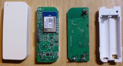
Hello, I will present here the Tuya water (flood) sensor with WiFi XR809 module and then I will show my alternative firmware intended for this type of sensors. It will be another port of my OpenBeken, which currently supports as many as four different platforms (BK7231T, BK7231N, XR809 and BL602).
I first decribed XR809 in this topic:
Open source firmware for XR809 compatible with Tasmota HTTP/Home Assistant
That was my first open source firmware for XR809 attempt. It was a very crude, first, proof-of-concept prototype that had to be recompiled for each device and didn't even support MQTT.
Later, I started working on WB2S (BK7231T) platform and released first version of my Tasmota replacement (along with pins configurator) for it:
[BK7231T] My HTTP server, configurator, MQTT support from Home Assistant
Some time later, after a brief analysis of BK7231T, BK7231N and XR809 SDKs I decided that it would be possible to support all those three platforms with single app.
I created an abstraction layer (called HAL) and started testing on various devices.
Just recently, I have also added BL602 support to my firmware:
Tasmota replacement for BL602, programming, pairing with Home Assistant.
but this topic is about XR809 so it's time to focus on the XR809 water sensor I got. Let's see how the OpenBeken works on XR3 module!
Here is the current repository of the project:
https://github.com/openshwprojects/OpenBK7231T_App
Purchase of a flood sensor
I found the product by searching for "Tuya Smart WiFi Water Leak Sensor Flood Leakage Level Alarm Overflow Detector". I bought it half a year ago, I don't remember for how much, but I can see that it costs about $ 13 now.
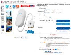
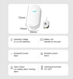
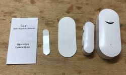
The distinctive housing tells us that the product is probably on the XR809. The XR809 door / window opening sensors have an identical housing.
The set requires two AA batteries for operation, not supplied by the seller. They must be purchased separately.
Normally the sensor works with the Tuya application, which I have tested before. Here I will focus only on my firmware.
The teardown of the flood sensor
This flood sensor looks identical to the door sensor discussed earlier. Even the board is identical. It's easy to get inside:
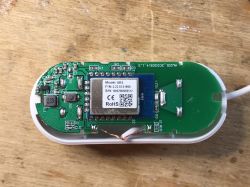
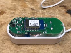
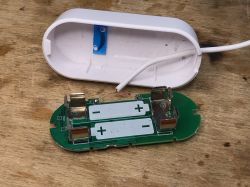
Apparently, in order to optimize costs, both versions of the sensor are produced together until the sensor needs to be soldered.
Uploading the firmware to the XR809
The firmware upload process is the same as in the previous XR809 topic:
Open source firmware for XR809 compatible with Tasmota HTTP/Home Assistant
Please see the topic above for details.
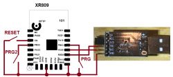
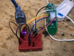
Soldering and programming (LDO TC1264-3.3V provides power, USB to UART is in 3.3V mode):
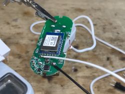
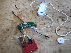

You can get the latest binary from here:
https://github.com/openshwprojects/OpenBK7231T_App/releases
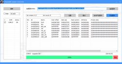
Programming success:
OpenXR809 configuration
The firmware presented here (OpenXR809) is the port of my OpenBeken, the configuration of which I discussed here:
LED WiFi RGBCW Tuya - teardown, BK7231N, programming with my Tasmota replacement
Garden Tuya CCWFIO232PK Double Relay - BK7231T - Programming
I recommend you to read it, here the process will be similar.
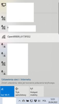
Connecting to an open WiFi network:
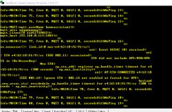
By the way, if you still have the UART connected, you can see information about the connection on it:
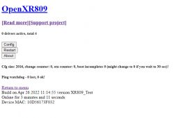
Configuration page is available at IP address 192.168.4.1 (here you can configure your device; set SSID and pass of your router, setup MQTT, pins, etc). If this IP does not respond, then you need to manually set the computer address to something like 192.168.4.25, because probably DHCP is not working):
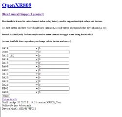
You also need to set the roles of the pins there - for example for the LED:
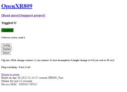
After this is set, you can control it via the button (and via MQTT if you configure it):
But the most important feature here is the water detector. It is on the same pin where the door / window sensor had a magnetic sensor.
For this sensor, you have to choose the role of the "DigitalInput_NoPullUp" pin, i.e. digital input without pull up resistors or pull down:
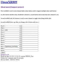
The input with pull up resistor will not work.
The value in the second column (by default it's 0) it's the index of coupled channel for the given pin. You can have many channels. The channels are used to link buttons and relays (and possibly LEDs) together.
Here, just to check if everything works ok, I connected the LED and the sensor via channel 0.
Let's see if it works:
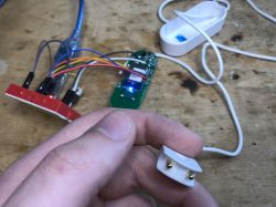
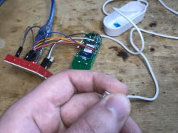
It works! Of course, if you want to convert the states to the opposite (eg LED or sensor), you have inverted pin roles available, with the suffix "_n". So "Relay" is a normal relay output pin, "Relay_n" is inverted.
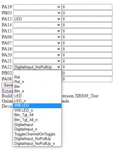
But I only connected this LED for a test. Ultimately, you will give it the role of LED_WiFi - it will inform you about whether the device has WiFi access at the moment:
Pairing with Home Assistant via MQTT
Now you have to somehow read the state of this sensor in Home Assistant. This is where MQTT comes into play.
Following on from the previous topics in the series, configure MQTT in Options-> Configure MQTT.
Restart the device.
Copy the device name from "Generate Home Assistant config", it will be for example oxr6173F032 . You can also change it in Config->Names (Short device name). Then manually fill in configuration.yaml in HA:
Code: YAML
Normally, in the configuration, I also include:
Code: YAML
i.e. the section responsible for testing whether the device is online, but here it is not necessary. This is not a bulb that we want to control, it is a water sensor that reports to us when the sensor's state changes.
Then restart the Home Assistant.
The sensor now appears on the panel:
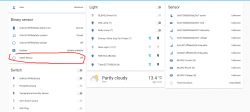
The sensor reacts to touch:
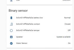
NOTE: If you have inverted "On" and "Off", you can change it both in pin roles (pin role to version with _n or without _n) and in configuration.yaml (swap payload_on and payload_off).
Other products by XR809 / XR3
There are several other products in this series. They are supported as well in the very similiar approach.
Door sensor:
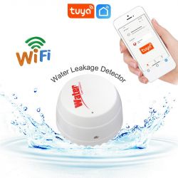
Flood sensor-cap shaped:
There are also other products from the XR809, for example a motion sensor or an LCD clock, but I will focus on them later.
Summary
The solution for the XR809 systems presented here is fully configurable and universal, it works similarly to the Tasmota. This is a much better way than what I described about a year ago, i.e. a "hard-coded" settings within the application for a given sensor, requiring recompilation in order to change, for example, the pin with the sensor or the MQTT password.
In order to test with the XR809, I have bought a few more devices, including:
- XR809 door sensor (it should work without any problems here)
- XR809 motion sensor (as above)
- calendar / thermometer / hygrometer from XR809 (based on TuyaMCU - it will be a bit of fun, but luckily, most of it is already implemented in the repository)
Ultimately, I also intend to support the other types of sensors that use a separate microcontroller (TuyaMCU) that controls the power supply of the XR809 or another module and turns it on only when you need to report a change of state (e.g. door opening). This is different from what I have described in this topic. This approach allows you to extend the life of the battery, because only the MCU is still working. You can read more about it on the Tuya website under the tab "Wi-Fi for Low-Power -> Serial Port Protocol".
That's it for now - if you know any other device with the XR809, let me know. If someone is interested in testing my firwmare, I invite you too - I will help you solve problems.
Cool? Ranking DIY Helpful post? Buy me a coffee.


