I will present here the world's first WB2S/BK7231T WiFi module programming tutorial. BK7231T chip can be found in many smart home devices, and up to this day people used to say that one cannot create own firmware for it. Nothing could be more wrong - I will show you step by step how you can setup the necessary SDK, compile firmware, burn it by UART and then run UDP, TCP, HTTP and finally MQTT protocols on BK7231 chip! The tutorial will be very practical, because we will end up connecting our WB2S with the Home Assistant server via MQTT! Such a "release" of WB2S will allow us to create an
open source , firmware, offering unlimited modification possibilities, transparent development process and independence from the manufacturer's servers.
NOTE: In the text I assume that the reader knows the basics of C programming and IP protocols like UDP/TCP/HTTP/MQTT.
A related topic about the XR809
It is worth mentioning that I have already described another WiFi module - XR809 in a similar way:
https://www.elektroda.pl/rtvforum/topic3806769.html#19447386
The SDK in both cases is quite similar, e.g. the presence of the Lwip library is repeated, although e.g. this cool HTTP server with the XR809 SDK is not available here. Maybe I'll port it... but let's start with the basics.
Preparation of hardware, connection of WB2S
WB2S will only require two UART connections. So you will need the pins:
- RX and TX (for programming)
- 2RX and 2TX (for checking the output log on the UART from the chip)
- of course, the GND and power supply, in this case I decided to connect to 5V before the LDO 3.3V
NOTE: if we want to power from USB, we have to remove the large electrolytic capacitor in front of the LDO. It often has a size of 680uF, and such a large capacity connected to the USB will consume too much current at startup, which results in a USB device reset and problems with WB2S programming!
For the demonstration, I used the NF101A relay:


But I also know other devices with WB2S inside, for example:
SmartSwitch Tuya WL-SW01_16 16A WiFi .
Here you can see WB2S pin roles:

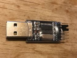
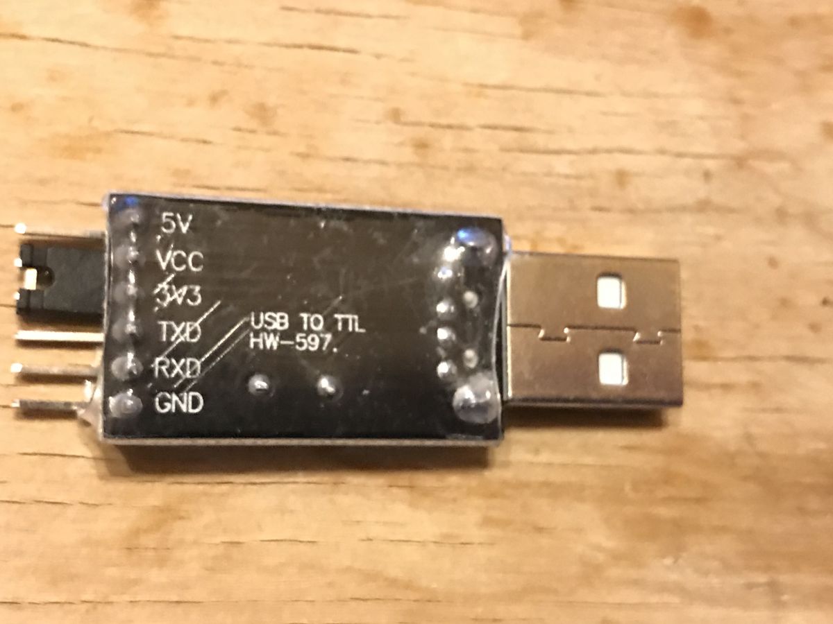
To connect the UART to the computer you will need two adapters, here with the signal logic levels set to 3.3V. I am using USB TO TTL HW-597.

Soldered wires to RX and TX (pads at the base of the module near the PCB) and the red cable to 5V (before LDO):

Soldered 2RX and 2TX (tiny test pads on the "back" of the module):

In order to secure the board and wires, I allowed myself to use hot glue temporarily:

Final work environment. You can see the necessary switch (programming needs) and two UART to USB adapters, one for programming, the other for reading the printf output:

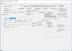
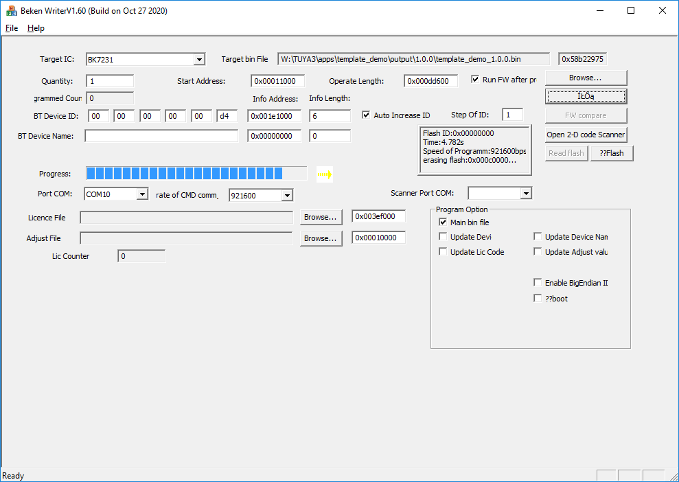
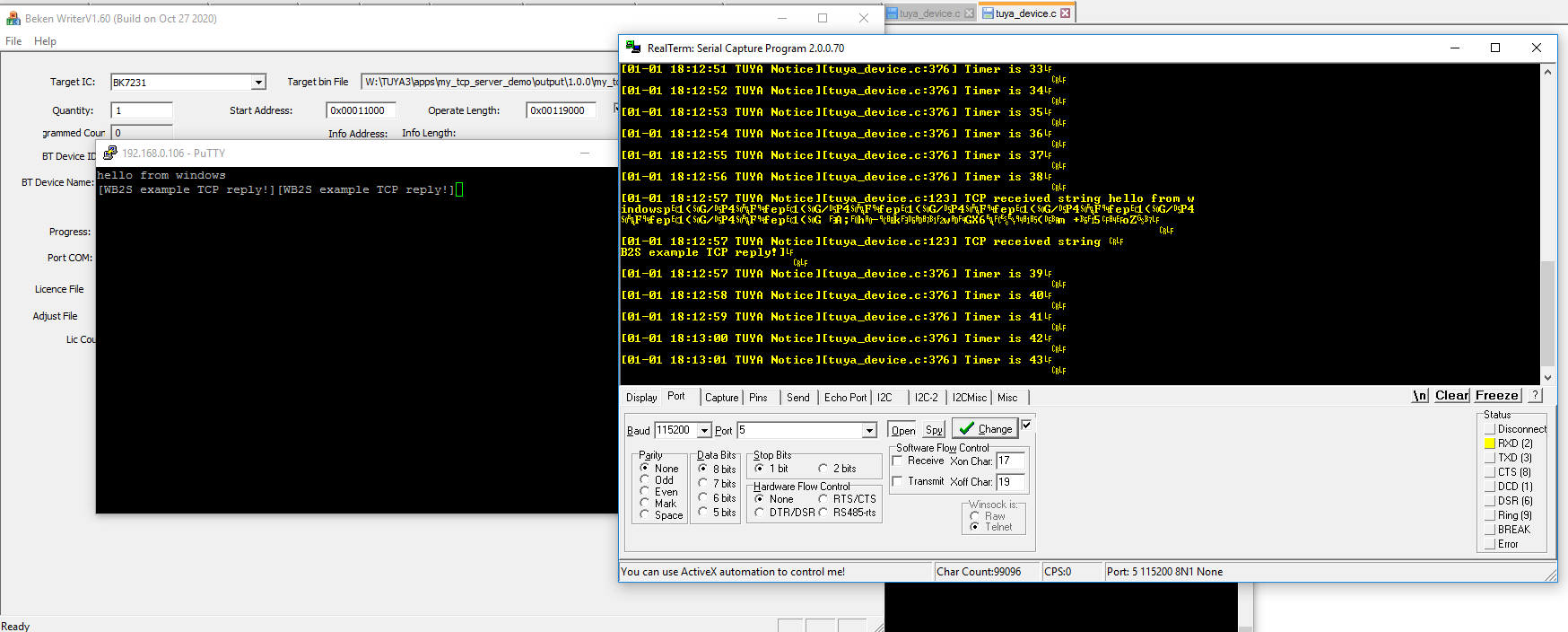
I use BKwriter (bk_writer1.60) to program the firmware, the programming / reading procedure is simple. We start the activity in the program, then turn off the WB2S from the power supply (and only from the power supply) with the button, and after a while we restore the power supply. The program should continue running as in the screenshot:

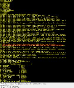
I am using RealTerm to read information from UART as in the screenshot below:
 The work environment is ready! WB2S can be programmed.
Configuration of the SDK and compiler
The work environment is ready! WB2S can be programmed.
Configuration of the SDK and compiler
I managed to achieve success with the load that is integrated with the Tuya environment (later we will try to "free" him from Tuya):
https://github.com/tuya/tuya-iotos-embeded-sdk-wifi-ble-bk7231t
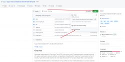
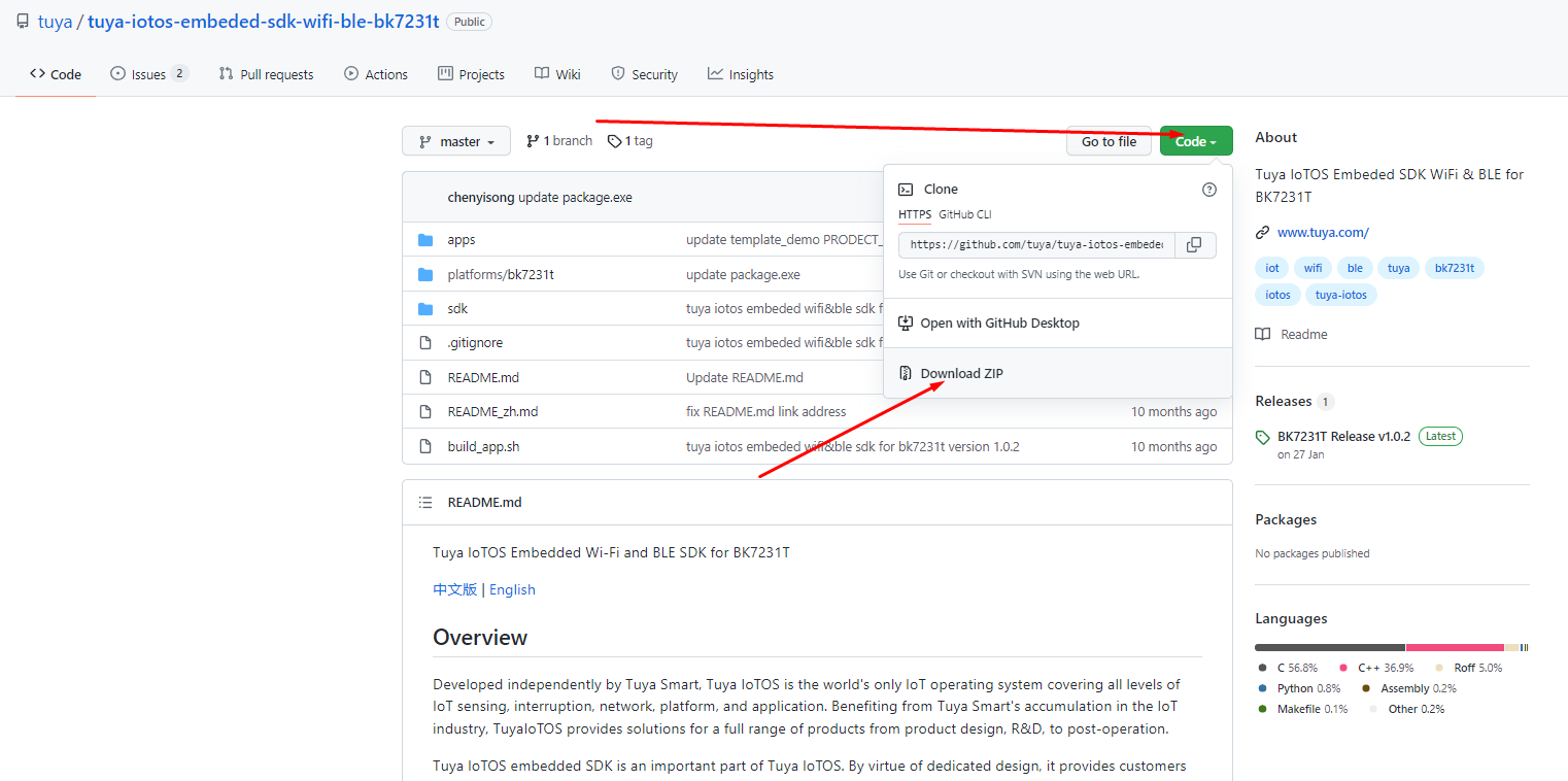
First, we need to download the entire repository. This can be done via git (command line or SourceTree GUI client):
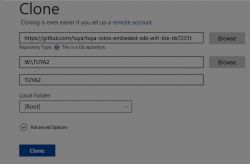
... or via the browser (Code -> Download Zip button):
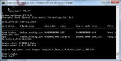
We unpack the package to, say, C: / bk7231 /:
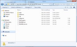
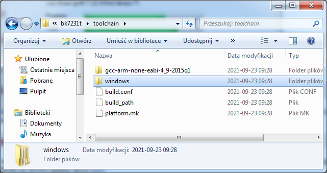
We get acquainted with the contents of the folder. Under the path
\ bk7231 \ tuya-iotos-embeded-sdk-wifi-ble-bk7231t-master \ platforms \ bk7231t \ toolchain we have a nice surprise - toolchain is here,
gcc-arm-none-eabi-4_9-2015q1 :
Next we need a linux environment to compile. I decided to emulate Linux on Windows via Cygwin. I have already described the installation of Cygwin here:
https://www.elektroda.pl/rtvforum/topic3806769.html#19628606
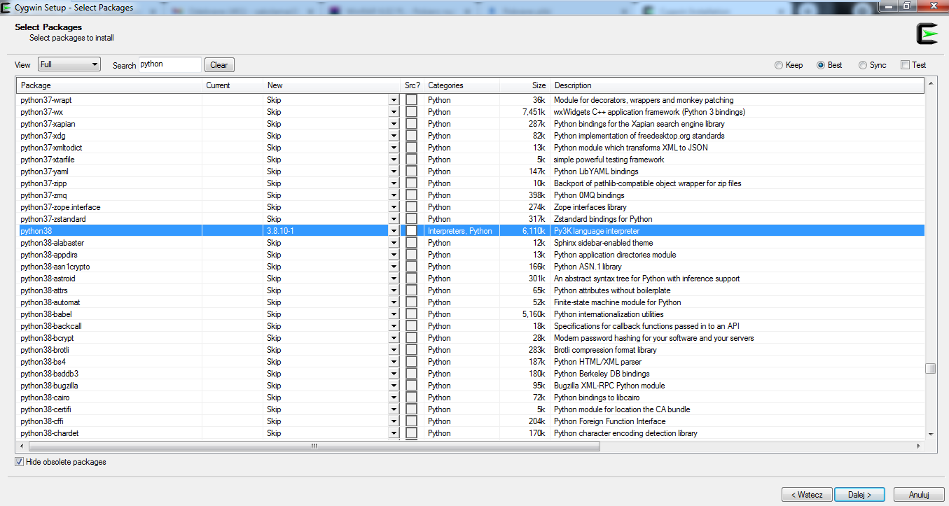
Installing Cygwin should include make and python 3.8.
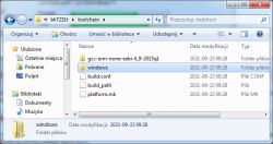
We run Cygwin and go to the SDK folder. We can list its contents:
The build_sh.sh script there contains everything we need.
We run it through:
Quote:
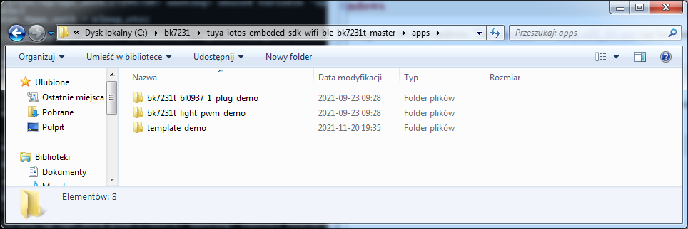
./build_app.sh apps / template_demo template_demo 1.0.0
The arguments indicate which project to build from the apps folder:
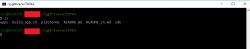
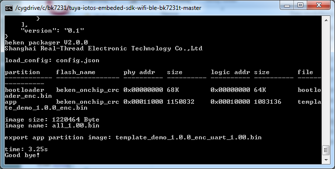
It will take some time to compile:
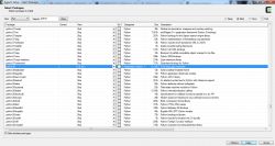
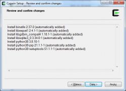
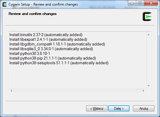
If we get an error saying "python" was not found then we need to install Python. For me it is in version 3.8.10. We install it via the Cygwin installer (then it will only add the necessary packages):
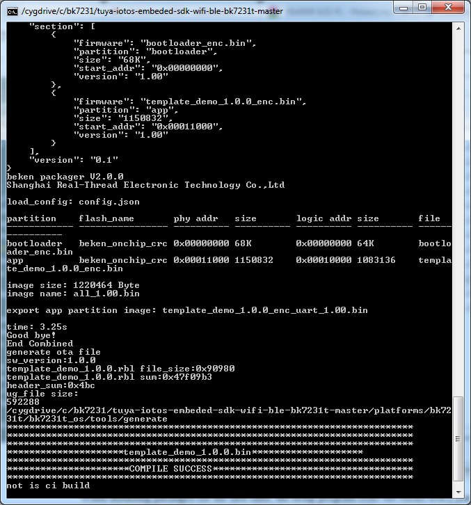
Then the compilation should be successful:
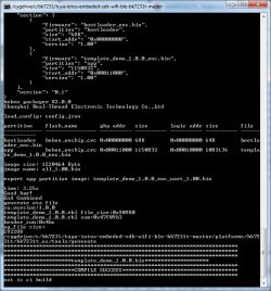
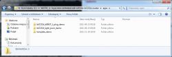
The results are in apps \ template_demo \ output \ 1.0.0:
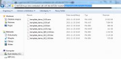
We use a file for uploading
template_demo_UA_1.0.0 but that's in a moment. UA may suggest UART in its name.
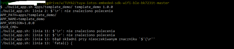
Compile errors related to \ r (carriage return)
If you still have problems running the build (build_app.sh), and these problems are related to the end-of-line standard (\ n and \ r), then the git client is probably causing the problem.
The git client automatically converts the nextline characters to standard on your platform, but if you are using Windows, git will convert them to Windows standard, when Cygwin expects a linux standard, which will result in an error like this:
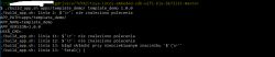
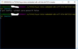
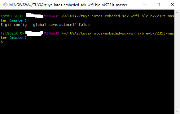
It is best to fix it in the git command line - turn off the automatic CRLF conversion and download the repository again -
git config --global core.autocrlf false :
You can also do it manually (e.g. via Notepad ++, Edit-> EOL Conversion tab).
The first hello world
Compilation is already working, but we still need to somehow verify that we can actually edit these projects meaningfully and that the entire build is going well.
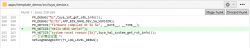
I suggest adding a printf somewhere, let's say the famous "Hello world".
This can be done in
apps / template_demo / src / tuya_device.c in pre_device_init:
We're compiling, it's time to upload the firmware.
The first load of the load
You will need the bk_writer1.60.exe program, which I attach to the topic.
The file that we will upload is template_demo_UA_1.0.0 (the file template_demo_1.0.0.bin will not work, BK will not start then). We choose it through "Browse" and click "Program".
We choose the appropriate COM port in the program.
Then turn off and on again the power supply from the module (but without removing the USB UART adapter from the computer port).
For me, this is the large button that cuts off the + 5V connected to the 3.3V LDO input.
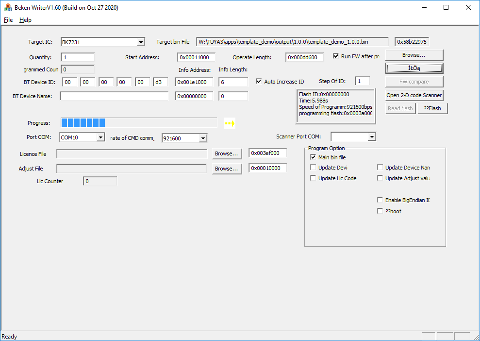
The erasing of the old firmware will begin:

And then uploading a new one:
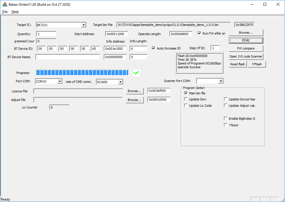
Done, after 18 seconds:

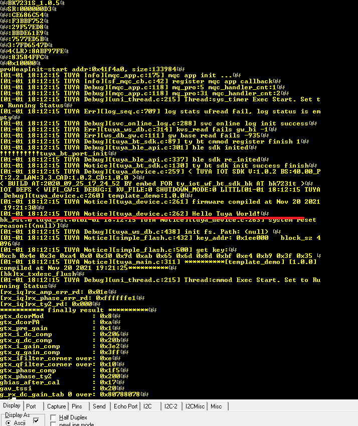
After restarting the device, our message appears:
Then the WB2S will automatically run the uploaded firmware.
Blink LED + Timers
Each tutorial usually starts with a flashing LED, so we'll cover that here too. We will flash the diode through a timer that starts every second. We will make all modifications in
tuya_device.c .
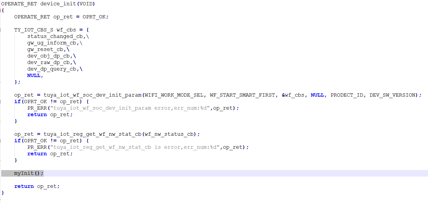
First you have to connect somewhere - I suggest device_init, this function is performed at device startup:
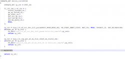
We create the myInit function ourselves. You need to initialize the state of the pins there and start the Timer:
bk_gpio_config_output - sets the given pin to output mode
bk_gpio_output - sets the value for the output of the given pin
rtos_init_timer - creates a timer (the function will be automatically called from time to time)
rtos_start_timer - the timer starts
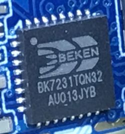
We just need to know which pin is which - where is GPIO24?
GPIO24 corresponds to P24, and the locations of P24 will be known from the WB2S catalog note:
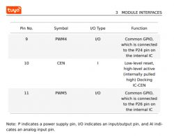
PWM4 is P24 or GPIO24, PWM5 is P26 or GPIO26.
NOTE: on some ESP modules the GPIO numbers differ from the pin outputs of the system, it probably is not the case here!
The state of the pins has also been changed and can additionally print something on the UART as part of the test:
NOTE: the relay control (MY_RELAY) will not work if you power the module from an external 3.3V source because the relay is powered from the 5V line (before the LDO).
Result:
[movie: 7d040c325f]
https://filmy.elektroda.pl/14_1638181056.mp4 [/ movie: 7d040c325f]
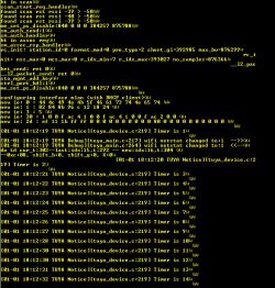
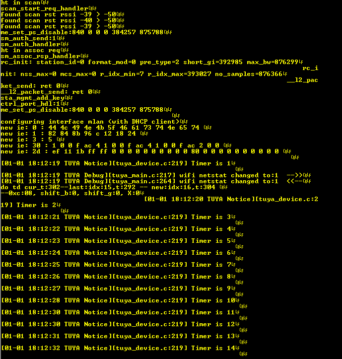
The countdown on UART also works:
 Connecting to a WiFi network
It's time to connect to the WiFi network using its SSID and password. Unfortunately, we will provide the password in plain text - so far we are not making the code more complicated. After connection, you also need to use DHCP to get the IP address assigned dynamically, but most do BK for us. Here's the finished feature:
In order for it to compile, we also need to attach one additional header:
We call this function e.g. from device_init.
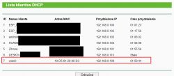
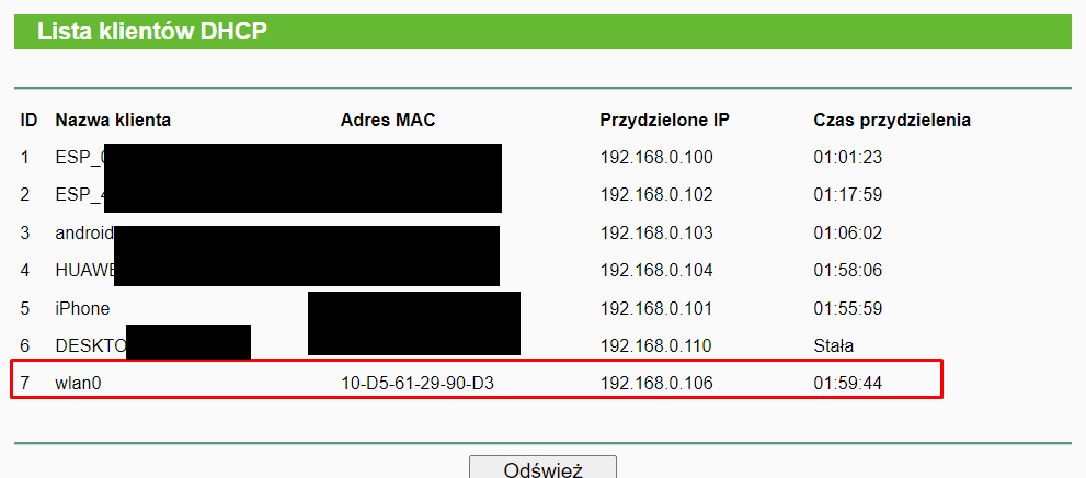
We can check on the router if the device is connected:
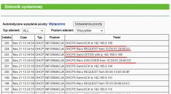
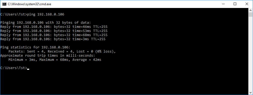
We initially check the communication with the ping command. We can use the -t switch to ping non-stop, not just a few times.
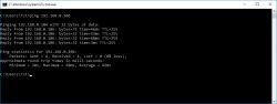
I recommend that you disconnect the power of the WB2S while pinging and check if it loses its connection - this is to verify whether we are actually pinging our device, or maybe something else.
Interesting fact: it is also worth knowing that there is a more advanced structure that allows you to connect to WiFi, you can also enter, for example, BSSID:
But I'm just covering the basics here, so for now it's time to move on to sending packets over the network.
UDP server
It's time for something more ambitious and allowing communication on the Internet. UDP server. We start with UDP, because UDP is simpler, it is a connectionless protocol that does not guarantee that the packet will reach its destination. The package is sent once and if it is lost, we will not even know about it. The connection protocol (and it offers retransmission) is TCP, which we'll cover later.
UDP support will be in thread. The recv command will block the thread from executing until it receives the packet. This solution is in contrast to "non-blocking" sockets, but we don't use them here.
Sockets on WB2S look like on Linux, so you can follow the examples of Linux (and actually also from winsock). For this reason, I will not describe here how 'bind', 'recv', 'recvfrom', 'select', etc. works. Everything is standard.
But let's not forget the headers, here are different than on other platforms:
Yes, sockets also come from LWIP.
For example, we create a socket like this:
On the basis of this, you can create a function:
Now all you have to do is send a UDP packet to that server somehow ... to test it.
For this purpose, I have prepared a program that sends the package in C # (on the Windows platform):
Time for a test. Does UDP communication work?
Works as you can see on both sides (WB2S and desktop application).
TCP server
We have already launched UDP, but UDP is not suitable for more serious applications because it does not have a reliability layer, it does not support automatic packet retransmission. Of course, we can implement something like this on UDP, but why?
That's what TCP is for.
TCP allows you to create a permanent connection with the client, separately we have the act of connection, data transfer, and connection closure.
Therefore, with TCP, each client will receive its own thread, which will run until the connection is broken.
Let's start by creating a TCP server thread:
Now, the main server thread.
When the TCP connection is established, a new client service thread is created - the tcp_client_thread function. The socket handle is passed to it as a parameter. This is needed because the recv and select functions are blocking here (blocking code execution until they receive something).
Client handler function:
Of course, you can use recv and send multiple times in this function. Len less than or equal to 0 will inform us about breaking the connection.
I also had to add auxiliary functions to the code, e.g. defining tcp_server_log, if so, I put the full code as an attachment at the end of the topic.
On the computer side, you can use Putty in Raw mode. The computer will connect to the server and send it what we type in the console.
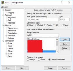
Let's check if TCP works now:
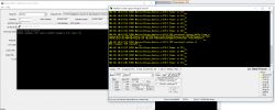
It works the most, but you can see that I lost the 0 character somewhere (byte zero, not in ASCII), as a result of which "bushes" entered the received message. This is not a problem, we can either send these 0 in the packet, or artificially add them to the end after receiving the packet (buff [len] = 0).
HTTP Server
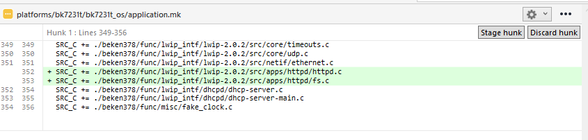
We also have the HTTP server ready, it is in the
lwIP [/ b] library. Only this time we need to add its sources to the [b] makefile [/ b] so that the compiler knows that its code should be included in the project.
HTTP server code is in [b]httpd.c and
fs.c from
platforms/bk7231t/bk7231t_os/beken378/func/lwip_intf/lwip-2.0.2/src/apps/httpd.
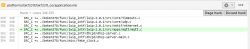
Let's add them to
application.mk:

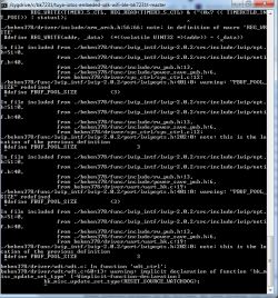
If we don't add them, we'll get linker errors when compiling, for example:
Quote:
W:\TUYA3\platforms\bk7231t\bk7231t_os/../../../apps/my_http_server_demo/src/tuya_device.c:736: undefined reference to `httpd_init'
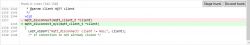
Now we still need to start the server. For now, let's just call
httpd_init in
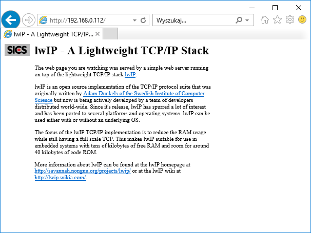
device_init:
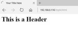
And that's enough - the WB2S web page is working now!
 HTTP Server - simple web page
The HTTP server from the library that is available in this SDK is built in a fairly static way and it will probably need to be redone, but it is still worth presenting here how to add a new file.
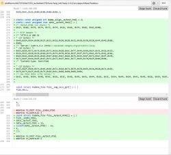
The contents of the file
platforms/bk7231t/bk7231t_os/beken378/func/lwip_intf/lwip-2.0.2/src/apps/httpd/fsdata.c
I will quote a fragment of it here:
Here we have hard-typed HTTP responses to a GET request with a given path. Here, such an answer is together with the contents of the file. Moreover, these responses are written in hex, not the normal text (char) that we can easily read. Of course, after converting the hex value to an ASCII character, we can read what is what.
You can easily "translate" such an array of bytes into ascii characters, just paste them into C code and print or preview in a debugger e.g. in Visual Studio, like this:
So, let's take a look at the full value from one of the buffers:
First there is the name of the file (terminated by a byte zero). The HTTP response starts with the "HTTP / 1.0" header, and the HTML response starts with <html>. This server here doesn't even "know" what is what, it treats it as one string.
We have a bit lower:
Here the structures representing the files are defined. Those cryptic "12" are the length of the filename at the beginning of the buffer. For example, the length of "/index.html" is 12 (11 characters + 1 NULL terminating character). It's a bit inconvenient that you have to manually enter this value into the code ... Let's see what makes up the fsdata_file structure:
Here we have a pointer to the next file (one-way list), a pointer to the name of the file (a string terminated with a byte zero character) and a pointer to its data (the body of the response to the GET, along with the HTTP header and the content of the file). Additionally, the length and field for the flags. Checksum support is disabled at this point.
The first file in turn is specified by this line:
#define FS_ROOT file__mytest_html
Can I add a file here? Absolutely. First, let's create its content, for example it could be:
Then let's convert it into hexes after the decimal point. This can be done ... by a separate C program that I ran on windows:
You still need to analogically convert its file name - say, "tst.html" - also to hex codes and add a 0 character ending the string, and then you can create an analogous table with the response to his GET request, also in
fsdata.c [/ b].
You also need to create an additional instance of the [b] fsdata_file [/ b] structure separately and attach it to a one-way list.
Below is the full 'diff' of what I wrote about [b]fsdata.c:
It works, as you can see below:
 MQTT support - necessary fix
It's time to move on to MQTT, a protocol that will provide us with, among others Home Assistant compatible.
Unfortunately, the MQTT library available in the discussed SDK is not complete. It lacks the implementation of MQTT client authorization. We have to implement it ourselves.
MQTT also comes from the lwip-2.0.2 library. The implementation is in
platforms\bk7231t\bk7231t_os\beken378\func\lwip_intf\lwip-2.0.2\src\apps\mqtt\mqtt.c
There is a
mqtt_client_connect function to be fixed, because it does not include the password and username in the package being built, so MQTT will only work in no login mode.
How do I know about this?
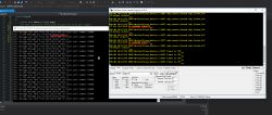
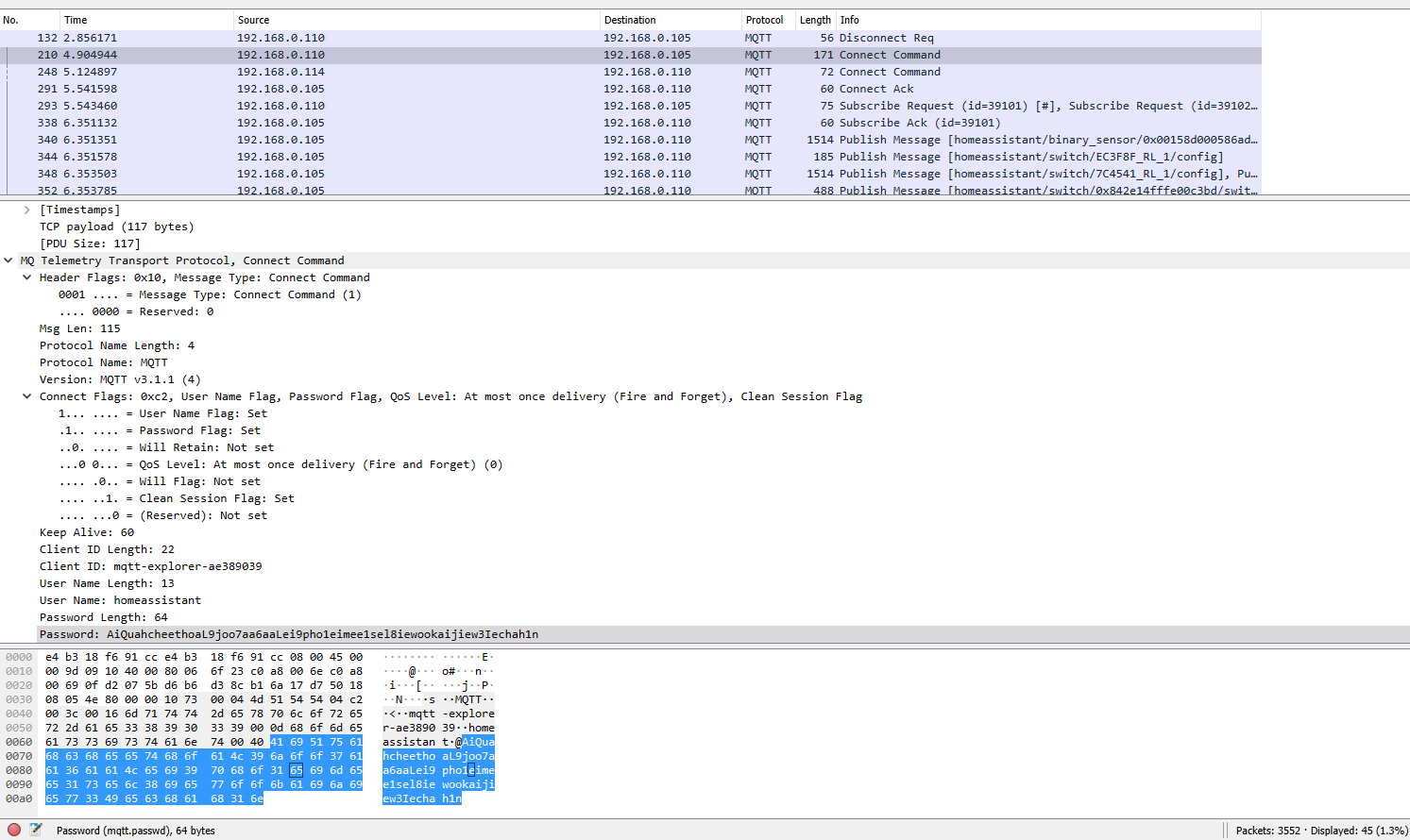
I compared the packages sent by WB2S (with the library unchanged) with the packages sent by the MQTT testing tool (MQTT Explorer). I used Wireshark to preview the packages. Below are the results:
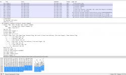 (by the way - Wireshark decodes MQTT packets automatically, a very useful feature!)
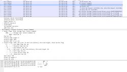
You can see what's missing, right?
Below I am attaching screenshots of my corrections, I will give you all for download at the end of the topic:
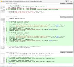
Additionally, you have to add mqtt.c to compilation in application.mk:
You can try compiling, but that won't work yet:
../../../sdk/lib/\libtuya_iot.a(libemqtt.c.o): In function `mqtt_disconnect':
/root/workspace_temp/EmbedSDKs/ty_iot_wf_bt_sdk_bk/ty_iot_wf_bt_sdk_bk/sdk/mid_mqtt/src/libemqtt.c:315: multiple definition of `mqtt_disconnect'
Debug/obj/mqtt.o:W:\TUYA3\platforms\bk7231t\bk7231t_os/beken378/func/lwip_intf/lwip-2.0.2/src/apps/mqtt/mqtt.c:1346: first defined here
collect2.exe: error: ld returned 1 exit status
It turns out that there is already a function in libtuya_iot.a called mqtt_disconnect. We cannot have a second name the same, we need to rename the one from mqtt.c:
MQTT library is ready, it's time to use it in practice.
MQTT support - step by step
Basic information about MQTT is in the readme file, but I'll cover it here anyway. MQTT service comes down to the following steps:
Step 1: Include the header:
Step 2: Client allocation.
Static method:
Dynamic method:
Step 3: Establishing a connection. The mqtt_connect_client_info_t also includes the username, password, etc., as needed.
NOTE: You can use mqtt_client_is_connected (client) to check the client status.
Step 4. Implementation of connection state handling (in the form of callback). This is done because the connection may take some time and we don't want to block the rest of our code from being executed (as in the case of blocking sockets).
Step 5: Implementation of data receiving callbacks (so-called in MQTT "publish"). In MQTT "publish" can be both ways, either from us or to us:
Step 6: Since we have a reception, we also need to be able to transmit - the publish send implementation:
NOTE: We can enter anything into the publish content, but for example Home Assistant uses the JSON format there.
Step 7: Disconnect / End MQTT Operation:
MQTT support - a practical example - compatibility with Home Assistant
Now let's use the knowledge gathered here and prepare a program that will report its condition through MQTT. For example, we can report temperature measurements in this way. Of course, we will generate the measurement itself randomly, this example does not cover anything other than MQTT.
You will also need a server for the demonstration - I will use the Home Assistant server here, prepared according to my tutorial:
https://www.elektroda.pl/rtvforum/topic3777098.html
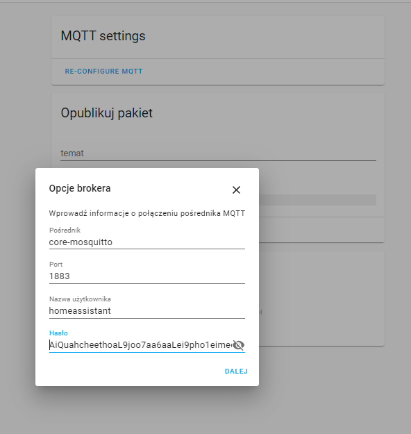
We need the MQTT username and password from our server. We take them from the settings of the Mosquitto MQTT broker:
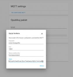
In the code, they are represented by the mqtt_connect_client_info_t structure. Let's initialize it with the appropriate fields:
The server IP is a bit different. Here is also the setting of callbacks:
Now the content of the less important, auxiliary functions:
The most important is the function that performs publish, that is sending the device state via MQTT.
For Home Assistant, it contains temperature information in the form of JSON:
{\"temperature\": \"45.5\"}
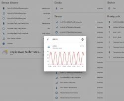
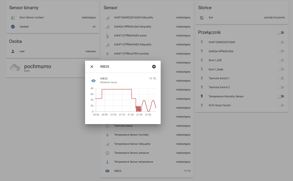
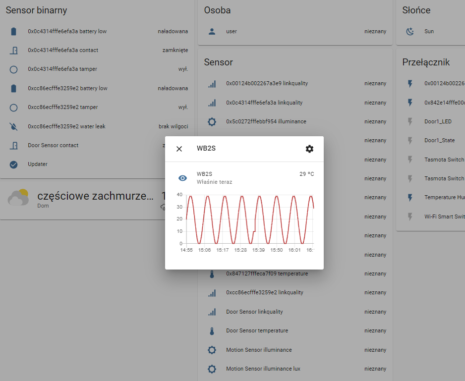
In the example below, I create a temperature value from a loop counter using the sine function so that the same values come out repeatedly. We will see it in the graph from the Home Assistant.
If publish fails, I retry the MQTT connection.
The second argument in mqtt_publish is the so-called 'topic'. It should align with what we're listening to in HA.
We have to call Publish ourselves - e.g. from a timer:
NOTE: The security issue of calling this library's functions from a thread other than the one that was started has not been fully checked by me.
On the Home Assistant side, we need to add an entry to /config/configuration.yaml. We inform the server what type of publish to listen to and how to process it:
sensor:
  - platform: mqtt
    name: "WB2S"
    state_topic: "wb2s"
    qos: 0
    unit_of_measurement: "ºC"
    value_template: "{{ value_json.temperature }}"
It is important that the names (name and topic) match, and that the value obtained from JSON ("temperature") has a real name.
If you have several devices, you can give them different names and have different, separate graphs.
As a result, in Home Assistant we get the following chart:
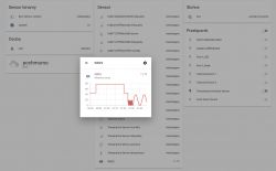
The full code of the MQTT example is also included in the appendices.
Download modified SDK and my examples
Below I put the SDK modified by me along with the projects of each of the examples in the app folder. NOTE - I cut the toolchain from the SDK because it took up over 600MB, so you have to download it from the repo separately ...
wb2s-updat...130-v1.zip (20.78 MB)You must be logged in to download this attachment.
bk_writer1...210523.zip (302.64 kB)You must be logged in to download this attachment.
Things left to do
There are a few things left to do here. Below is a list, in a random order:
- this HTTP server from the used SDK for WB2S is weak, either I will convert it or I am sporting the server with the XR809 SDK (which I have already launched)
- I did not work out the save to the settings memory so that WB2S remembers what WiFi connected to, but this is not a problem
- one could try to "free" this WB2S a bit more from the Tuya environment because at the moment it is in the background to some extent. You need to clean the tuya_device file from unnecessary function calls and maybe even experiment with bypassing libraries (but in fact, the bootloader will be useful for us ... we do not want to program it later via JTAG, which is also possible, if I remember correctly)
- the world does not live by WB2S alone, you should check what with WB3S and similar
Open source firmware project for WB2S and similar
Most of the necessary mechanisms needed to prepare universal, open programming (similar to eg Tasmota) for these systems are already operational.
Therefore, I am starting a project with the temporary name OpenWB2S. The project will be developed in parallel with the OpenXR809 project, which will work similarly, but on the XR809 chip, details here: [url = https: //www.elektroda.pl/rtvforum/topic3806769.html#19447386] Own open firmware for XR809 compatible with Tasmota HTTP / Home Assistant [/url].
Project support - interested parties can support the project through:
- testing (in some time I will create a github repository for both projects)
- collecting information in what devices are what modules (you can send photos, etc., even in this topic. I know about the list
https://templates.blakadder.com/)
- paypal donation:
https://paypal.me/openshwprojects
(There are some of these different devices and I want to test as many of them as possible, moreover, I have already put a lot of teardown at
https://www.elektroda.pl/rtvforum/forum507.html, the funds will go to the purchase of more devices)
- if you have, for example, WB2S modules that you have left after replacing with ESP12F or damaged smart devices, etc., I can accept them for testing (contact PW)
There are many more modules similar to WB2S, for example there is WB3S and I also have to test it soon ...
Summary
This is the second seemingly closed WiFi module that I was able to work out. It was similar with the XR809 - also no one knew that it could be run on independent software. It was similar here with WB2S.
Now I plan to develop my software for both of these modules and soon I will also set up github repositories for both projects. The goal will be to make a Tasmota equivalent with MQTT support. It is difficult for me to say how long it will take, and it also depends on the response and interest, but I can already reveal that the next topic I want to present on the forum will be a detailed MQTT tutorial, but this time on the XR809.
The topic will be updated and corrected.[/b][/b][/b][/b]


Comments
I have a bunch of Tuya modules for you ;) I'd also recommend to broaden the project name since the same Beken chip is used in other modules and in non tuya devices [Read more]
I just received some smart plugs which unfortunately have this module instead of ESP. Will try flashing one per your instructions. [Read more]
That's great, if you're interested in donating Tuya modules for testing then please PM me. I also know that some of WB modules might be pin compatible with ESP12F modules, so.... so I could use ESP12F... [Read more]
There's no need to. Somewhere in the lwip directories there should be a program fsgen (or something like that) that creates this filesystem from the indicated files. [Read more]
Indeed, there is makefsdata. I think I underestimated the authors of this library a bit. https://obrazki.elektroda.pl/9040063700_1638310967_thumb.jpg [Read more]
Great work! I look forward to seeing more on the Beken chips! I was able to use inspiration from your XR809 project to take control of a water leak sensor that uses Tuya serial protocol, MQTT HA discovery,... [Read more]
@drtfav it's nice to see more people using my tutorial. I also worked on Tuya protocol several times, for example here: https://www.elektroda.com/rtvforum/topic3819498.html I also found a smart touch... [Read more]
I bought mine locally from a USA hardware store, but there are some of the same form factor on AliX. No guarantee of what's inside though, of course. [Read more]
well, I can see that you have pushed the topic forward nicely :) congratulations. The bk7231 is a very nice chip, much more interesting than the esp8266, it competes calmly with the esp32 ;) I am finishing... [Read more]
Tasmota's code is entirely based on the Arduino Core, so the latter would have to be ported in the first place. [Read more]
I am confused by your link (https://www.elektroda.com/rtvforum/topic3819498.html). The Tuya protocol is well known and they make it public (https://developer.tuya.com/en/docs/iot/tuya-cloud-universal-serial-port-access-protocol?id=K9hhi0xxtn9cb).... [Read more]
I know that Tasmota has Tuya protocol support, I used Tasmota with this protocol for example here: https://www.elektroda.pl/rtvforum/viewtopic.php?t=3825966&highlight= I even referenced this link: https://tasmota.github.io/docs/TuyaMCU/... [Read more]
@p.kaczmarek2 Is it possible some devices may be fuse locked and are unable to program? I have some HBN BNC-60/UT152T plug switches that use the WB2S module, with the BK7231 chip. When i use the Bkwriter... [Read more]
Have you managed to read-out any of the original Tuya firmware with bk_writer? I tried on one of mine briefly but it just appeared to time-out. (I'm trying to reverse-engineer the UART protocol used by... [Read more]
Oops... I had gotten pretty far reversing the Beken writer tool, when I tried a few different search terms and found this Python implementation, apparently from the company itself, just not on its organizational... [Read more]
I don't know if BK chip can be locked, but I remember having issues with programming XR809 with low quality USB to UART bridge. Could you try using the same one I have? If you are powering your module... [Read more]
Well, before I found the Python script, my goal was partially to write an open source Python replacement for the bk writer app 🤣. It was also good practice with Ghidra and with x86 assembly, so... [Read more]
Are you able to receive the debug log output print on the second UART? There is a large bulk capacitor on your board photo. Is it at VIN side of 1117-3.3V? If you want to be able to power board from... [Read more]
Hmm, same "no response" results with the WB8P. I now suspect a more general problem: do you upload firmware through rx1/tx1 or rx2/tx2? If not that, maybe it's my uart adapter, cp2102 based. I ordered... [Read more]