.
Hello my dears. .
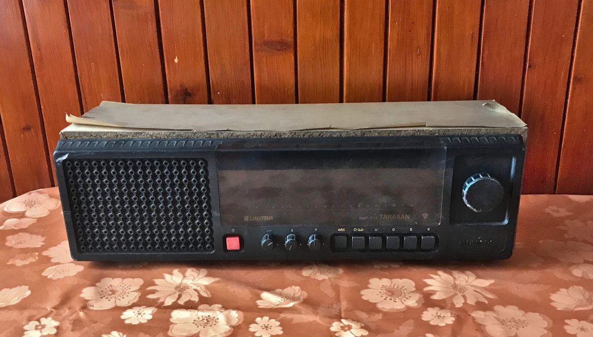
I would like to invite you to a short teardown of an old Polish Taraban 2 radio, which unfortunately came to me already in a rather bad condition. As standard, I will present here detailed photos from the inside and then post the schematic and documentation.
Taraban 2 - DMP-602 .
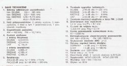
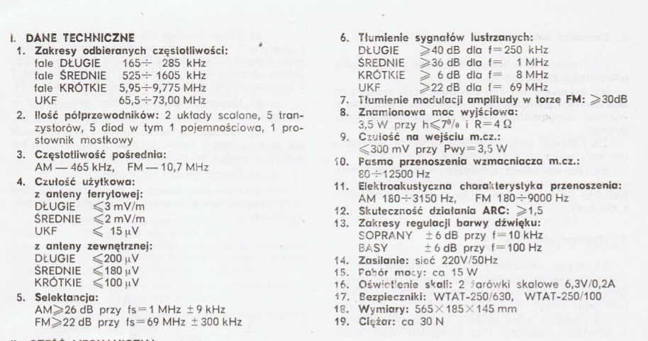
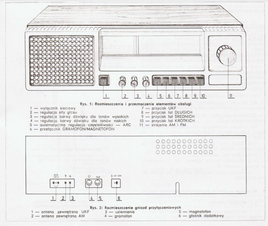
Taraban 2 receives long wave, medium wave, short wave and UKF. The AM intermediate frequency is 465kHz and FM is 10.7MHz. For more details, I refer you to the manual:
.
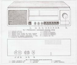
Which connector is which, button roles, etc:
.
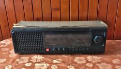
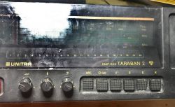
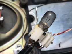
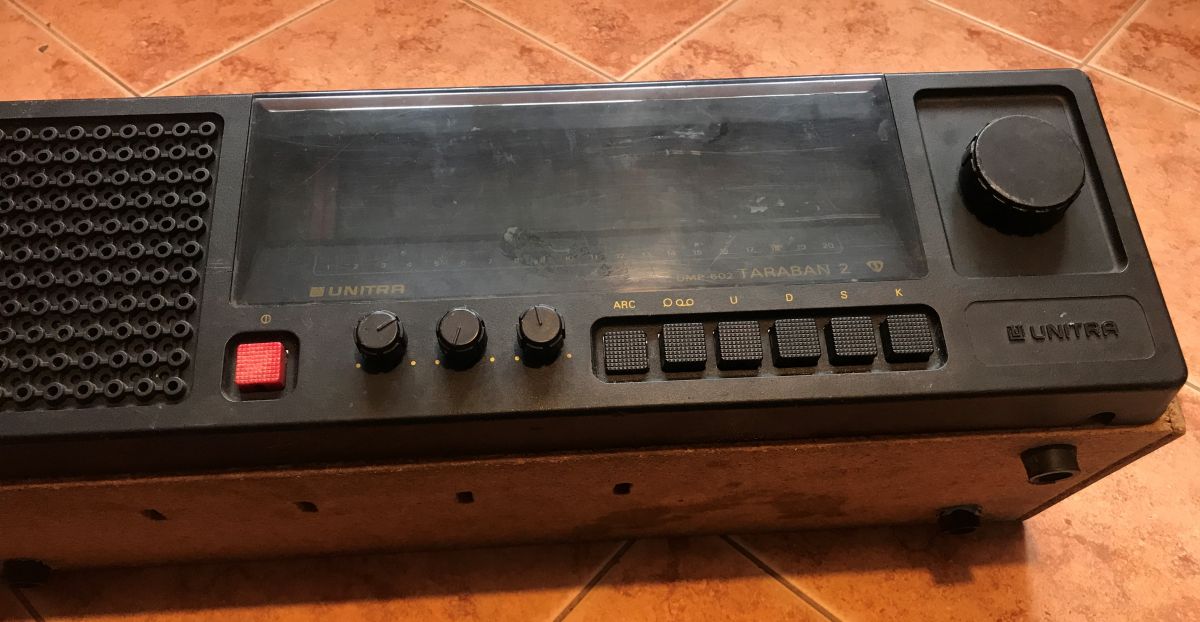
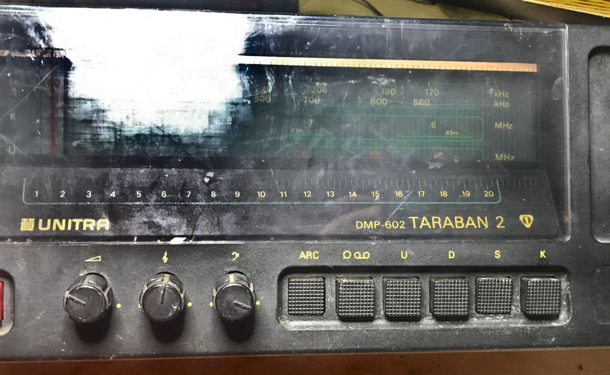
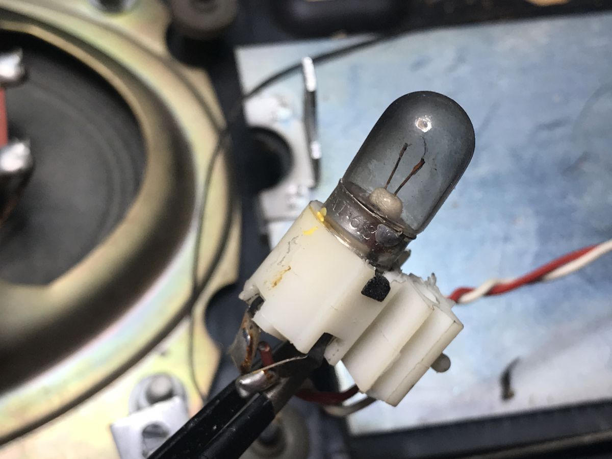
Photo of the front, the scale is illuminated using ordinary 6.3V/0.2A bulbs, which we will see soon.

.
.
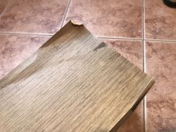
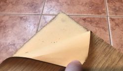
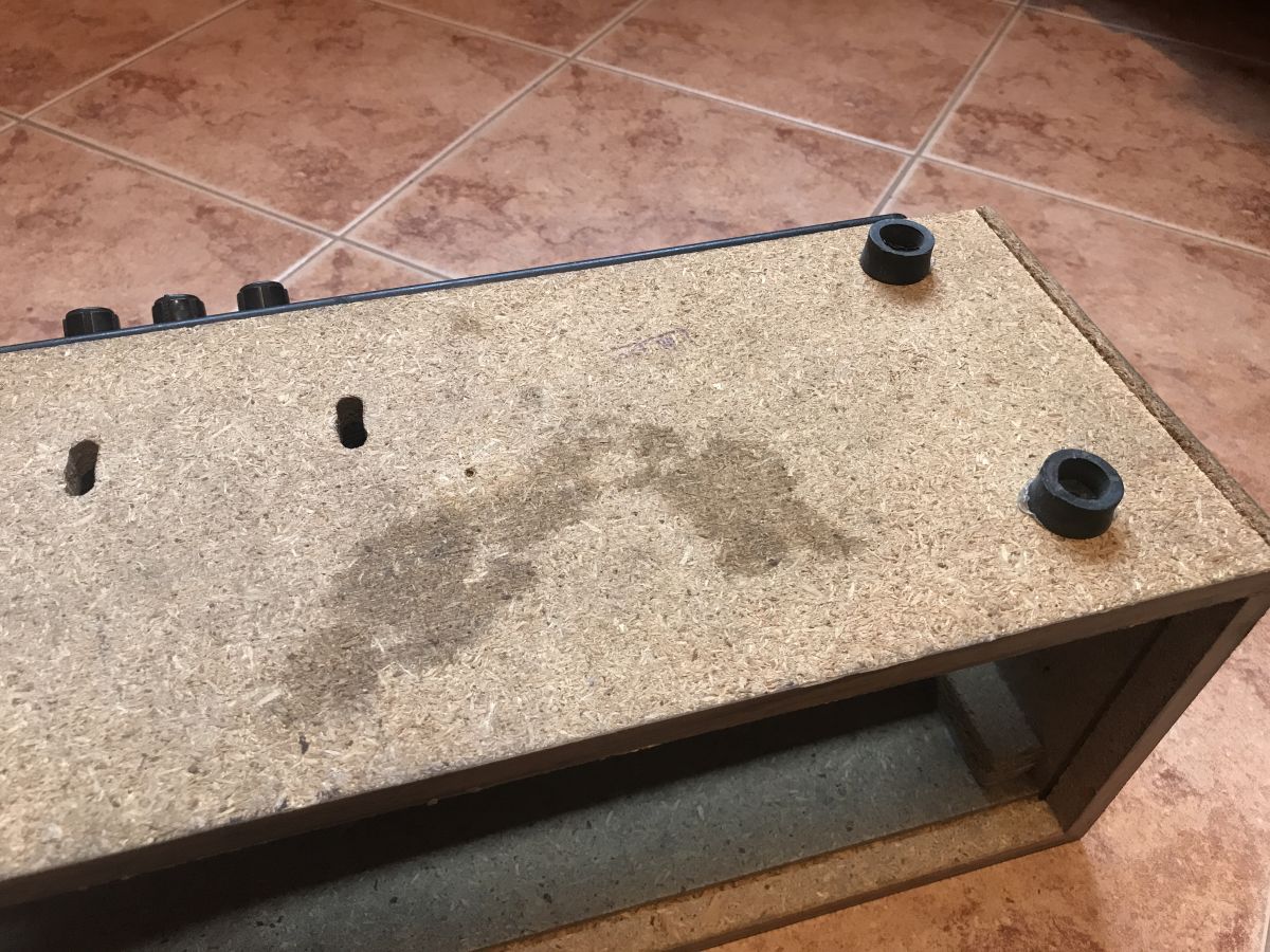
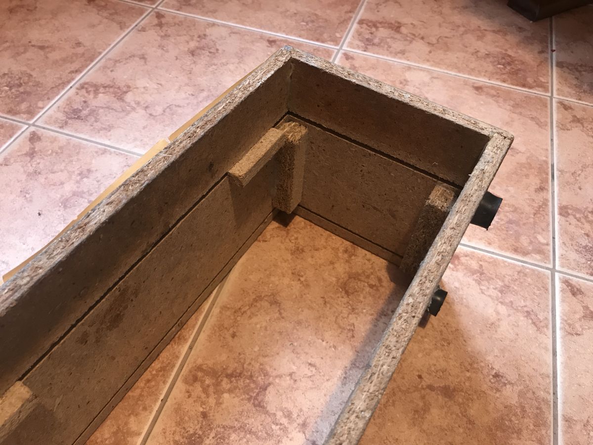
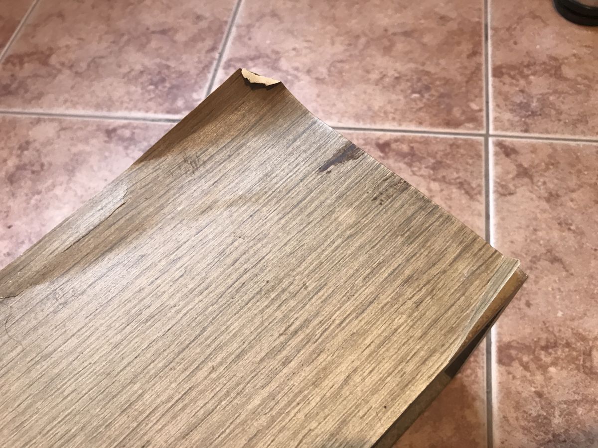
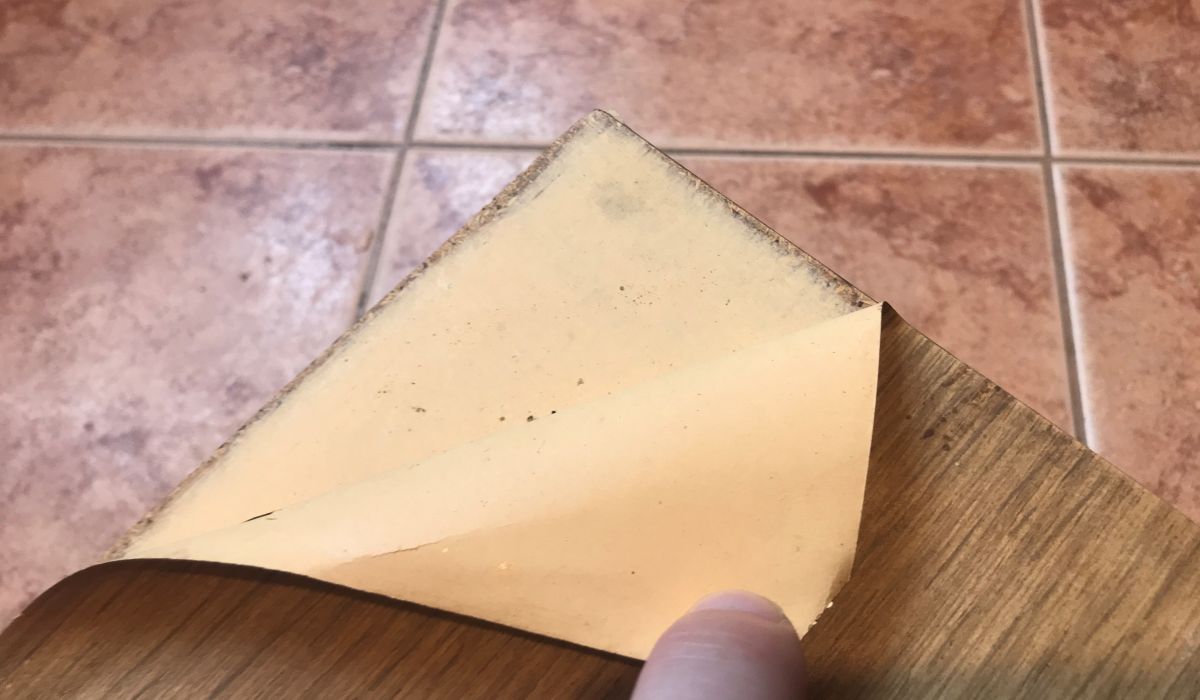
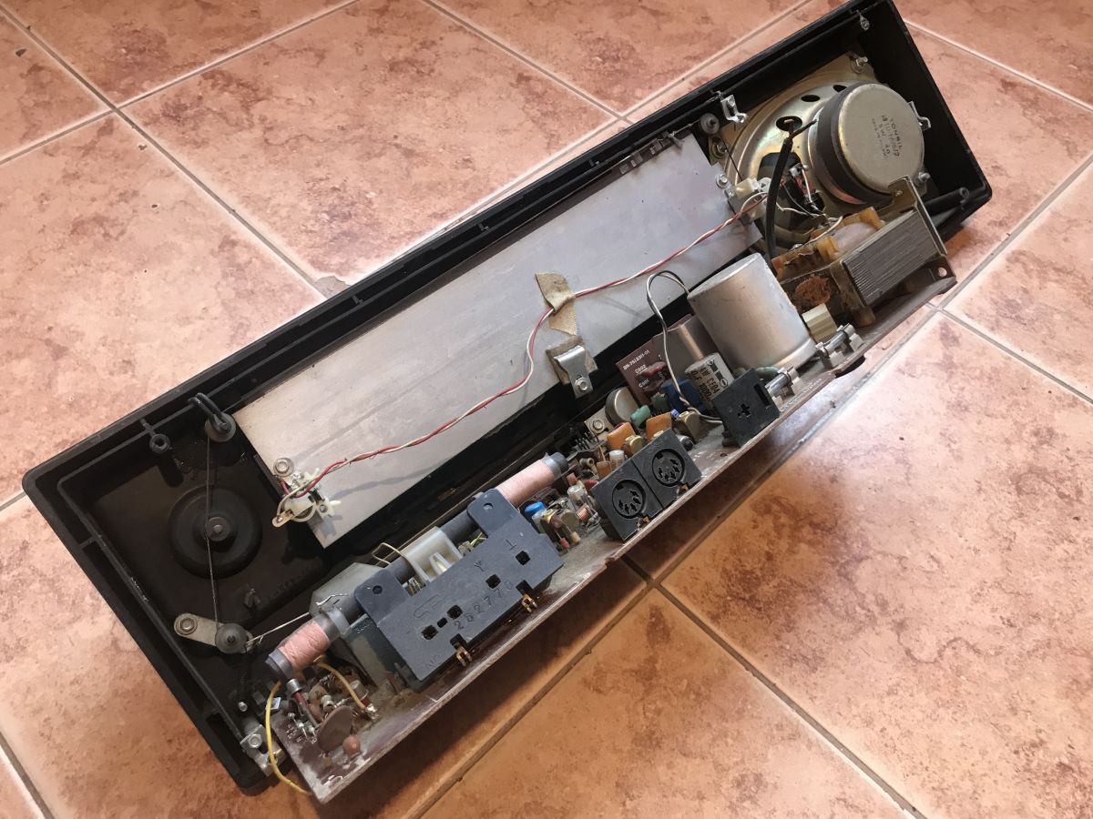
The receiver, unfortunately, I have already salvaged in very poor condition. Both the casing and the interior:


.
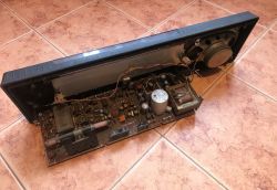
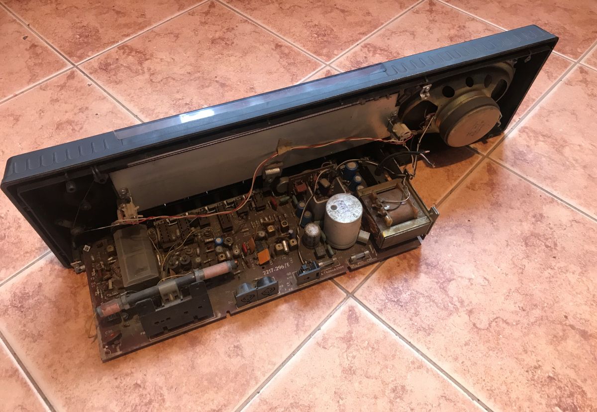
The back plate is missing, the electronics can simply be removed along with the front:
.
Antenna connector also torn out:

.
.
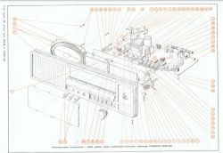
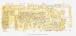
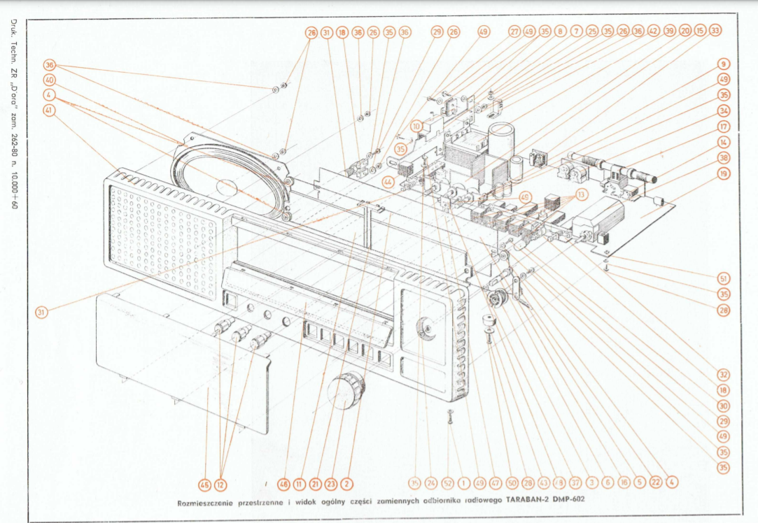
There is a spatial arrangement of the elements in the documentation:
.
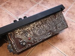
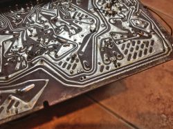
PCB tracks. Some of the solders look poor:
.
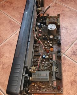
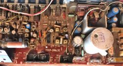
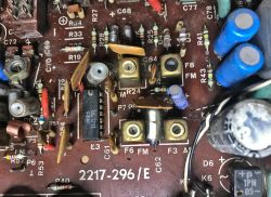
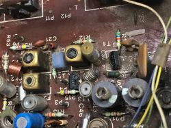
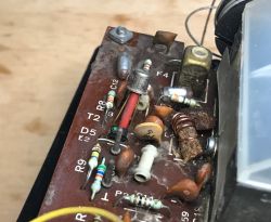
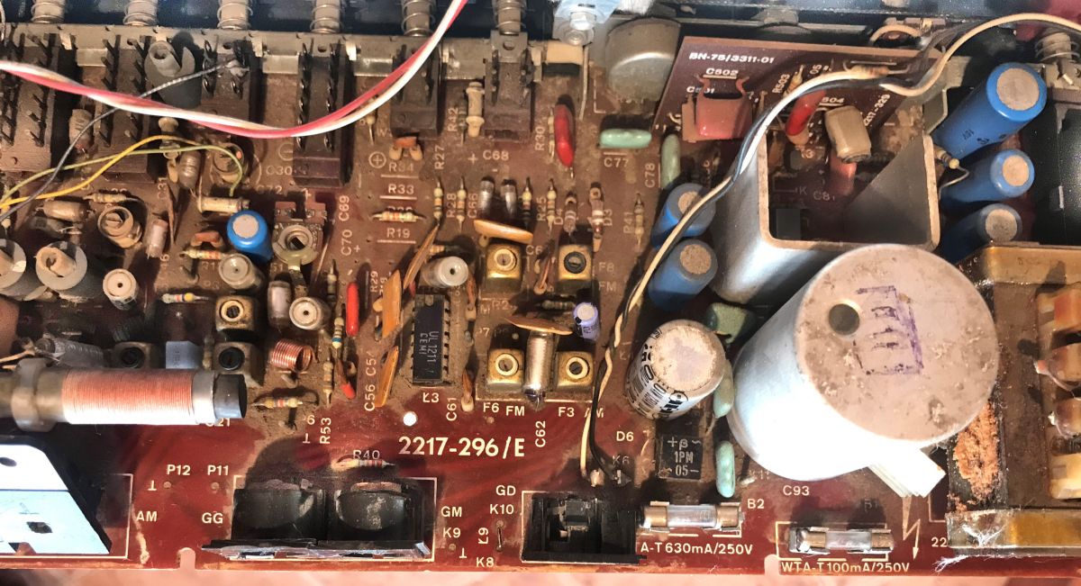
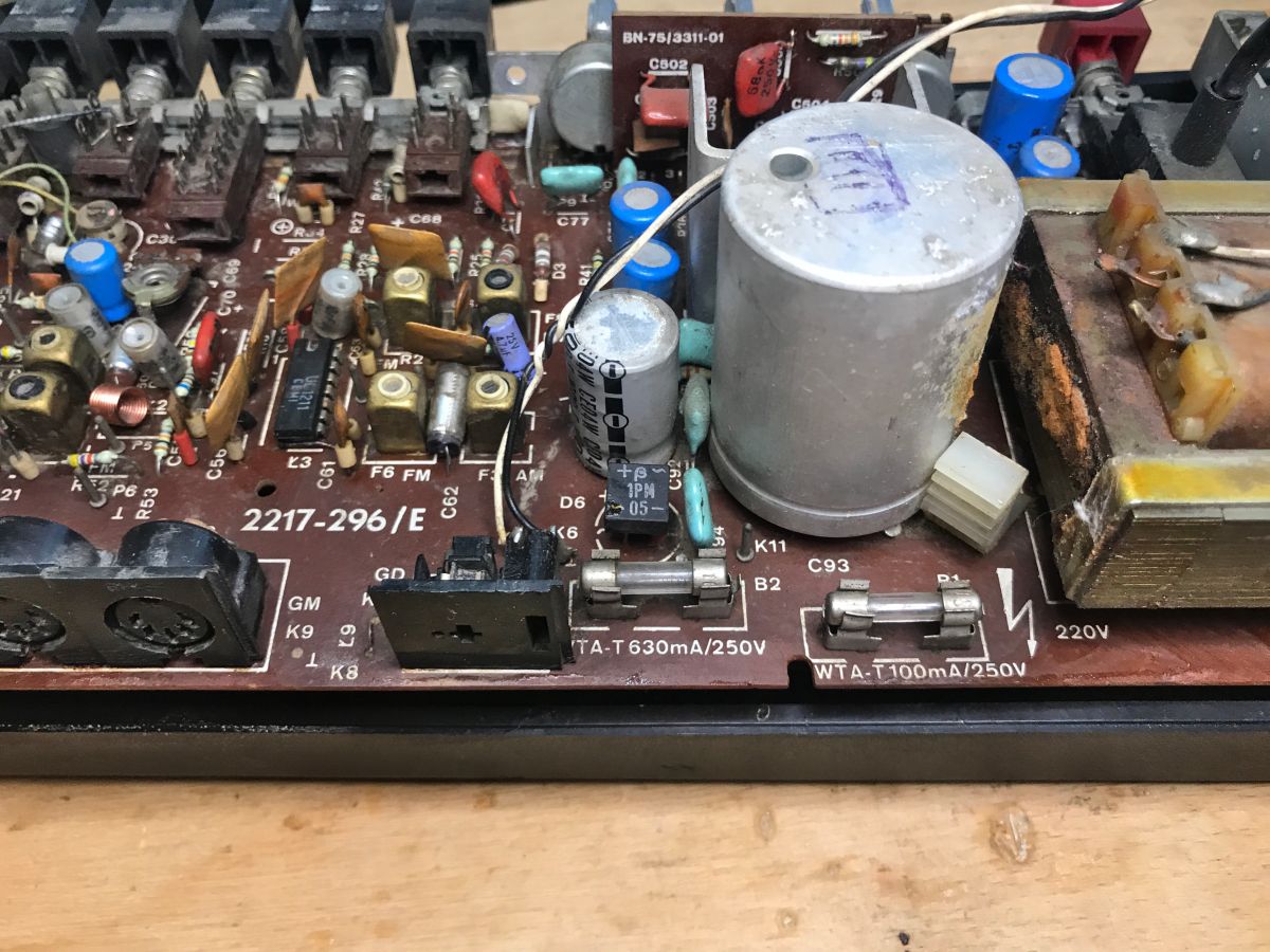
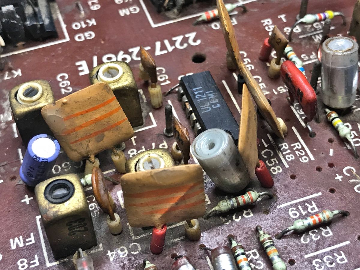
Time for clearer pictures of the board. I had to at least pre-clean it, the layer of dirt is extremely thick.
Here you can see, among other things, the fuses, the 1PM05 rectifier bridge and the UL1211 IC:
.
.

.

.
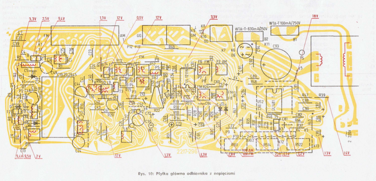
We even have the board voltages listed in the service manual:
.
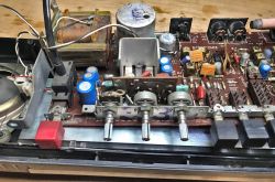
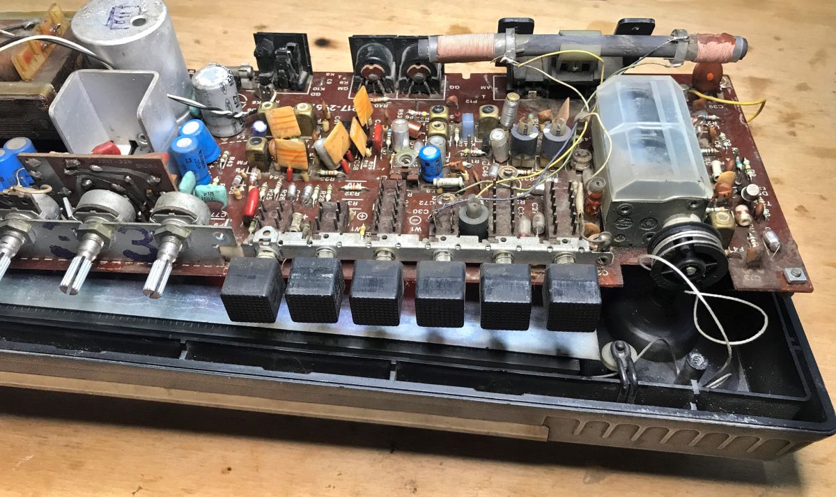
Rails with potentiometers, switches:
.

.
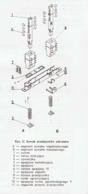
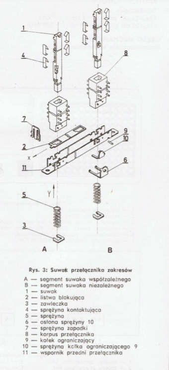
The mechanism for switching ranges is shown well in the manual:
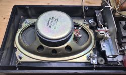
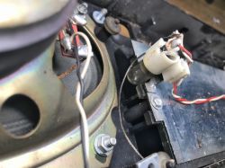
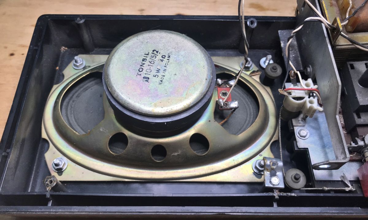
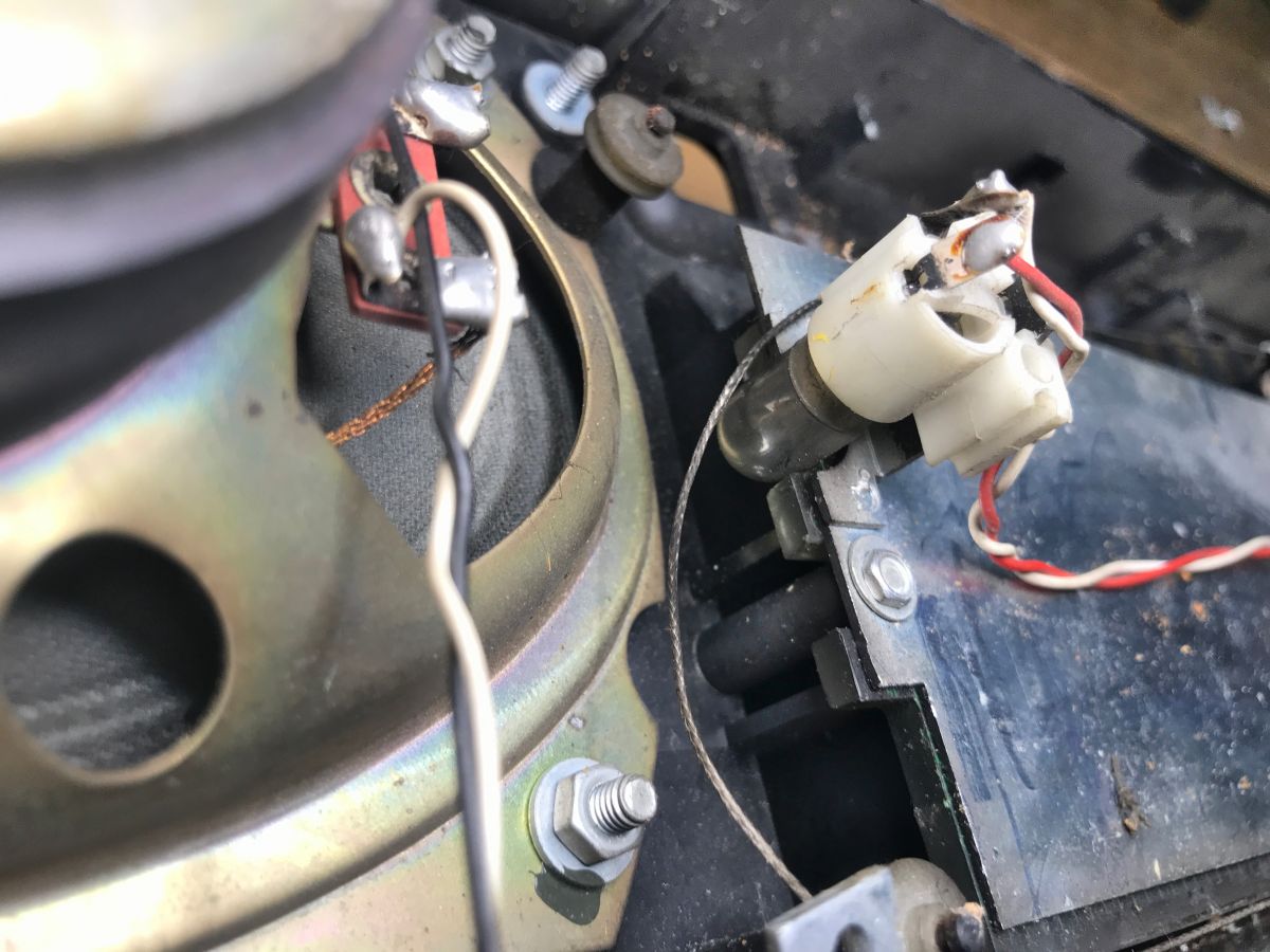
Tonsil speaker GD10-16/5/2 5W 4Ω Made In Poland:
.
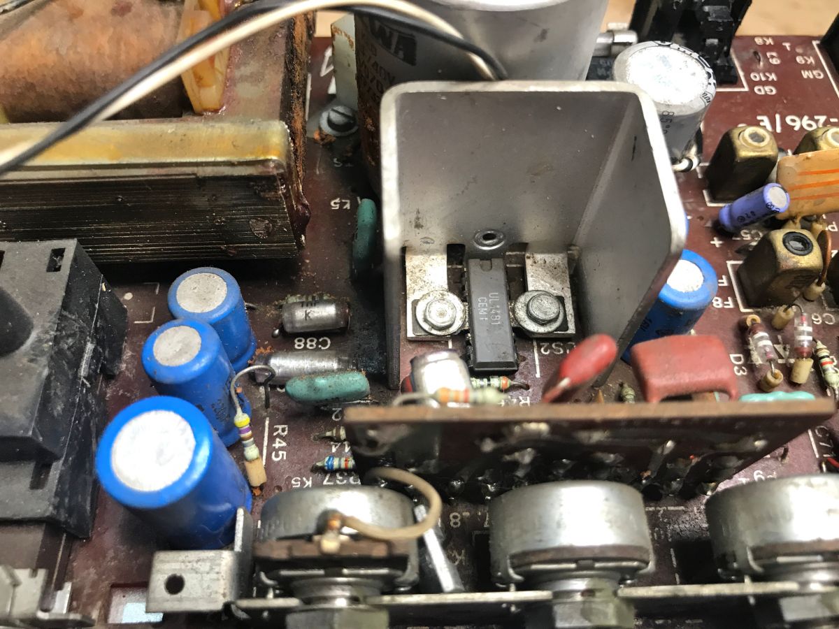
The second IC inside is a UL1481 CEMI, together with a heatsink:

.
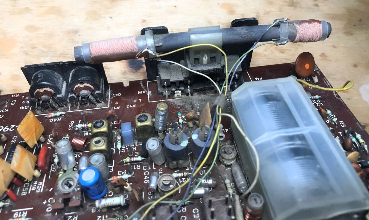
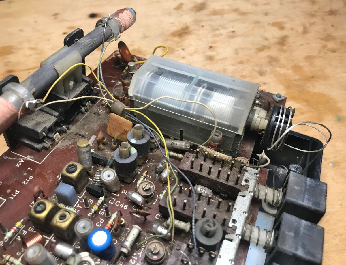
Ferrite antenna, tuning capacitor:

.

.
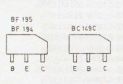
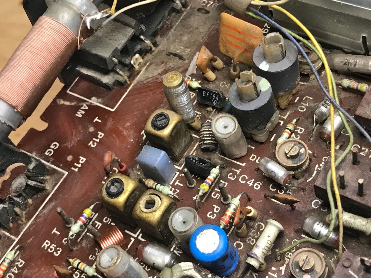
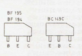
Transistors w.c. BF194 in the characteristic housing of the time:

.
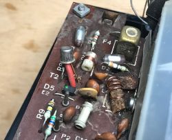
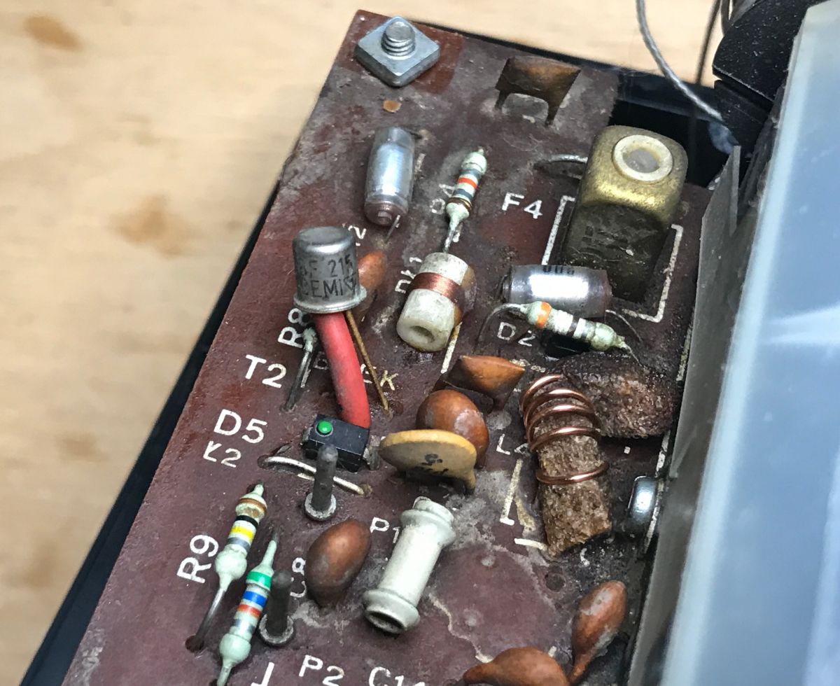
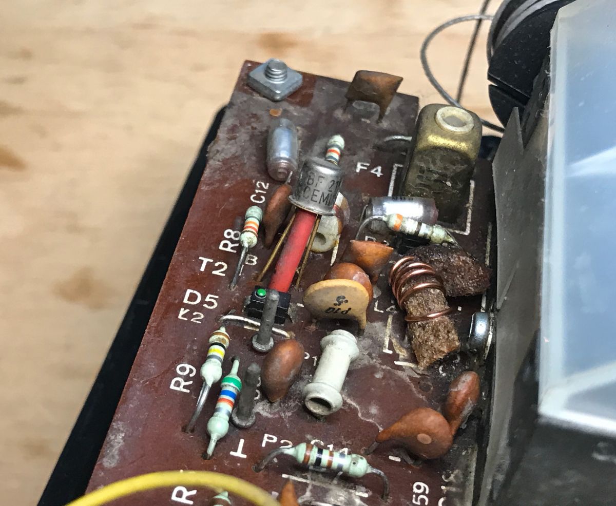
BF215 transistor and a characteristic capacitive diode (warp) with a green dot, probably BB105G (yes, I checked on the schematic).
.
The aforementioned backlighting - the bulb:
.
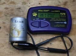
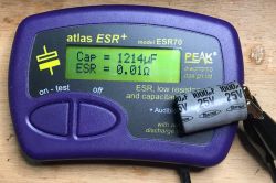
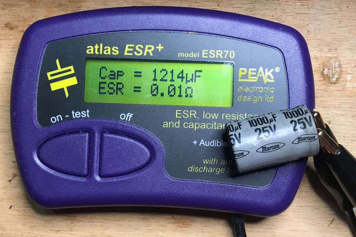
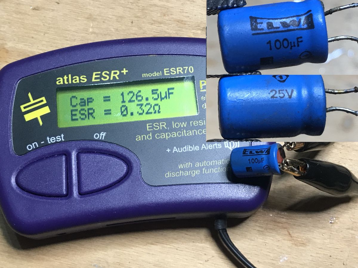
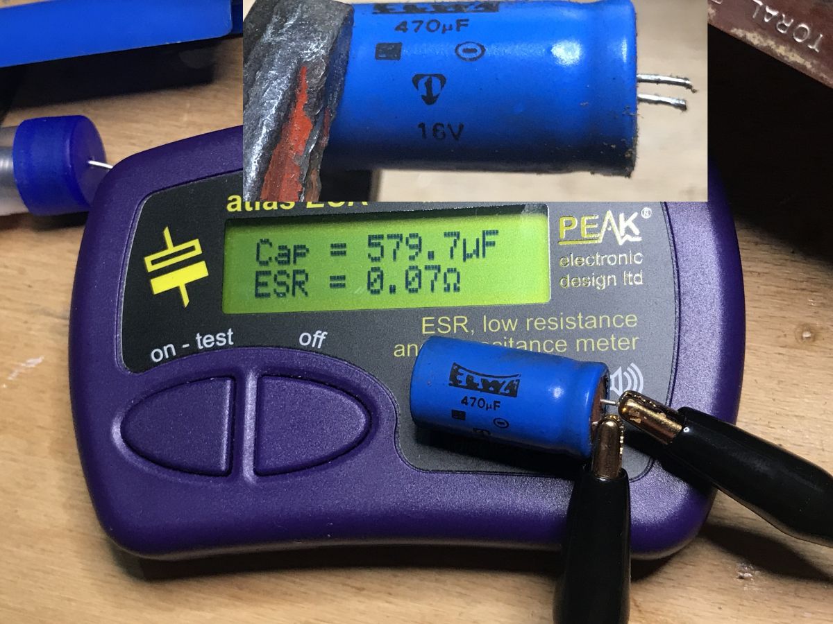
Out of sheer curiosity I decided to check the capacitance and ESR status of the ELWA electrolytic capacitors from inside this radio. For this I used a rather expensive ESR70 meter that I have tested and know does not overestimate the measurements. Would the capacitors be in poor condition or also perhaps their capacity has increased? Let's see:
fe
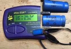


Capacities are consistently higher than nominal, but overall it is not so bad, although I refer to the ESR tables to assess specific results. The results are repeated for a further 100uF/220uF not included in the images.
Service manual (in Polish) .
For this radio, detailed documentation and instructions in Polish are available online. I don't see the need to over-quote it here, I'm simply attaching the PDF for download (schematic also inside):
Taraban_2_...MP-602.pdf (14.64 MB)You must be logged in to download this attachment. .
Summary .
A radio in much worse condition than the ones I usually find. I don't know how much time it has spent in the air and rain. I know you can get one very cheaply in good condition, but it's not about just buying. Maybe if I fix the solders I can get something going with it. At least the head doesn't look like it's been tampered with, so it's better than if it had been completely ripped out due to some failed attempt at UKF tuning.
That's it for now, perhaps I'll come back to this receiver in another topic in the form of commissioning+tuning.
 .
.
 .
.
 .
.
 .
.
 .
.
 .
.
 .
.
 .
.
 .
.
 .
.

 .
.
 .
.
 .
.
 .
.
 .
.
 .
.
 .
.
 .
.
 .
.
 .
.
 .
.
 .
.
 .
.
 .
.
 .
.

 fe
fe

Comments
I am always impressed by these service manuals for old equipment. they would be useful for modern :) [Read more]
I see you are starting to collect old receivers. Repairing a pcb is sometimes less of a problem than repairing a box. Too bad you don't have the backs because you would be able to determine the year... [Read more]
I had the same thought, everything laid out as if on the palm of my hand. [Read more]
I have a radio like this. It has been in continuous function in the kitchen for over 20 years (when it was tuned) playing sometimes several hours a day. From failures: - scale bulbs burnt out - replaced, -... [Read more]
I had another version with a round speaker, after a few years I converted the amplifier itself to stereo. Together with the MK232P also converted to stereo (a'la deck) it surprised the neighbours who had... [Read more]
Unfortunately nowadays, if anything, whole modules are replaced and manufacturers do everything to make repairs as difficult as possible. In equipment manufactured some time ago, the ubiquitous latches... [Read more]
. On the large electrolyte you have a production date of 0481 - April 1981, this is more or less also the production date of this receiver, with a deviation of plus a quarter [Read more]
Such a measurement is best carried out after such a capacitor has been connected for at least several minutes to a voltage close to its rated voltage and then discharged to zero. Especially if the capacitors... [Read more]
The head is identical to many other Dior designs. In my 1:1 Duet it's the same, even the layout of the components on the laminate is similar. Tuning, apart from the L3 coil which is cumbersome to tune,... [Read more]
Even so, ELWA used to make good capacitors. So much time, and the capacitance holds BA! with a hook. In those days ESR was not as important as it is today. [Read more]
I too have such a radio receiver only it is a Taraban 3 R-510. The difference between the one in the article and the one I have is only in the front casing, there is a different scale and there are different... [Read more]
. Except for the small ones so up to 10u 22u These are generally always replaceable. [Read more]
. That's right. They can even short-circuit the inside and mess with the circuits. [Read more]
good radio still plays today [Read more]