
I will present here the interior of the garden "smart" two-channel Tuya / WiFi transmitter model CCWFIO232PK, which I received as a donation from the user @strigon from Canada to run my firmware for microcontrollers from the Beken family. The topic will be divided into two parts - the interior of the product and then connecting the programmer and loading the batch. But first, a special thank you to @strigon - thank you, the template for this product has already been added to my firmware! If someone wants to send me some other product for testing, I invite you to PW.
What is it about?
As a supplement, I recommend that you familiarize yourself with related topics, including with my initiative to write my own batch for BK7231 (Tasmota's ESP equivalent):
WB2S / BK7231 Tutorial - we create our own firmware - UDP / TCP / HTTP / MQTT
[BK7231T] My HTTP server, configurator, MQTT support from Home Assistant
I also described the manufacturer's applications (Tuya / eWeLink / Blitzwolf / SmartLife) in previous topics from the series. I will not discuss its topic here.
Additionally:
my Home Assistant tutorial
Additionally, a twin topic, but with a product from BK7231N (not T!):
Qiachip Smart Switch - BK7231N / CB2S - interior, programming
Tests with the Tuya application, automation
I have tested Tuya products in this section so many times that I will not discuss the "obvious" functionalities here. I refer to the previous parts -
e.g. here.
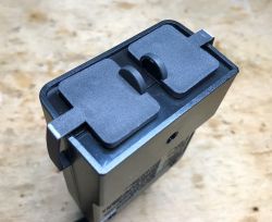
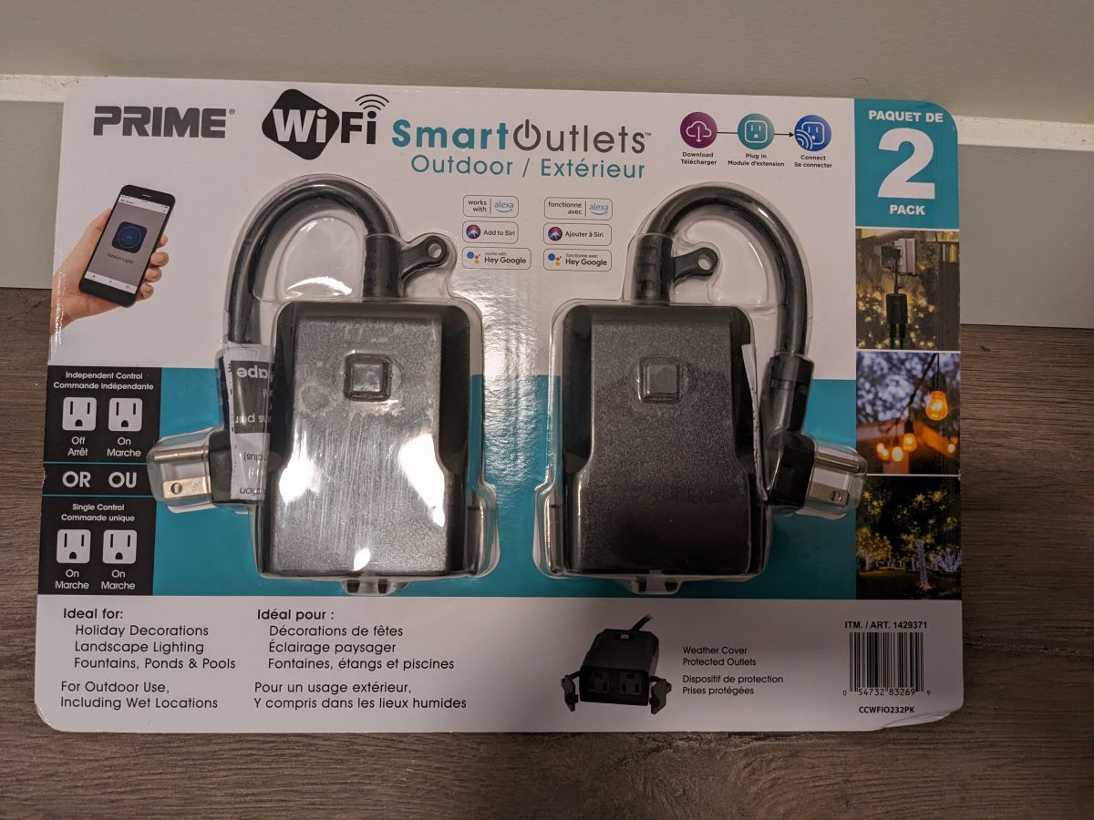
Kit contents and product interior
He bought the @Strigon kit at a Costco store. In his opinion, earlier versions were based on ESP8266 and Tasmota could be used with them, but Tuya is switching to Beken chips ...

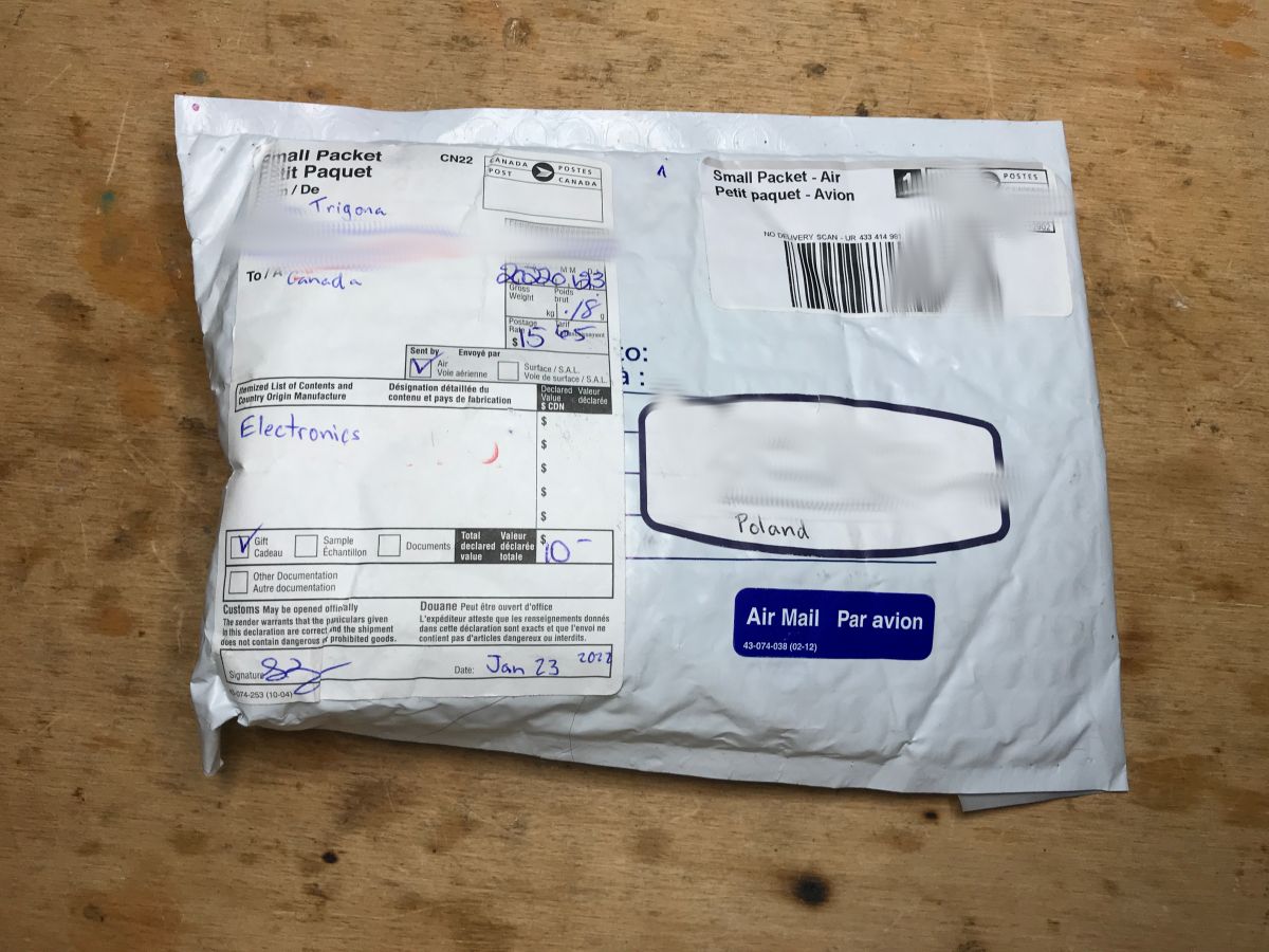
The parcel came to me after quite a long time:
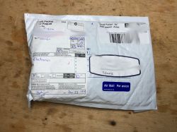
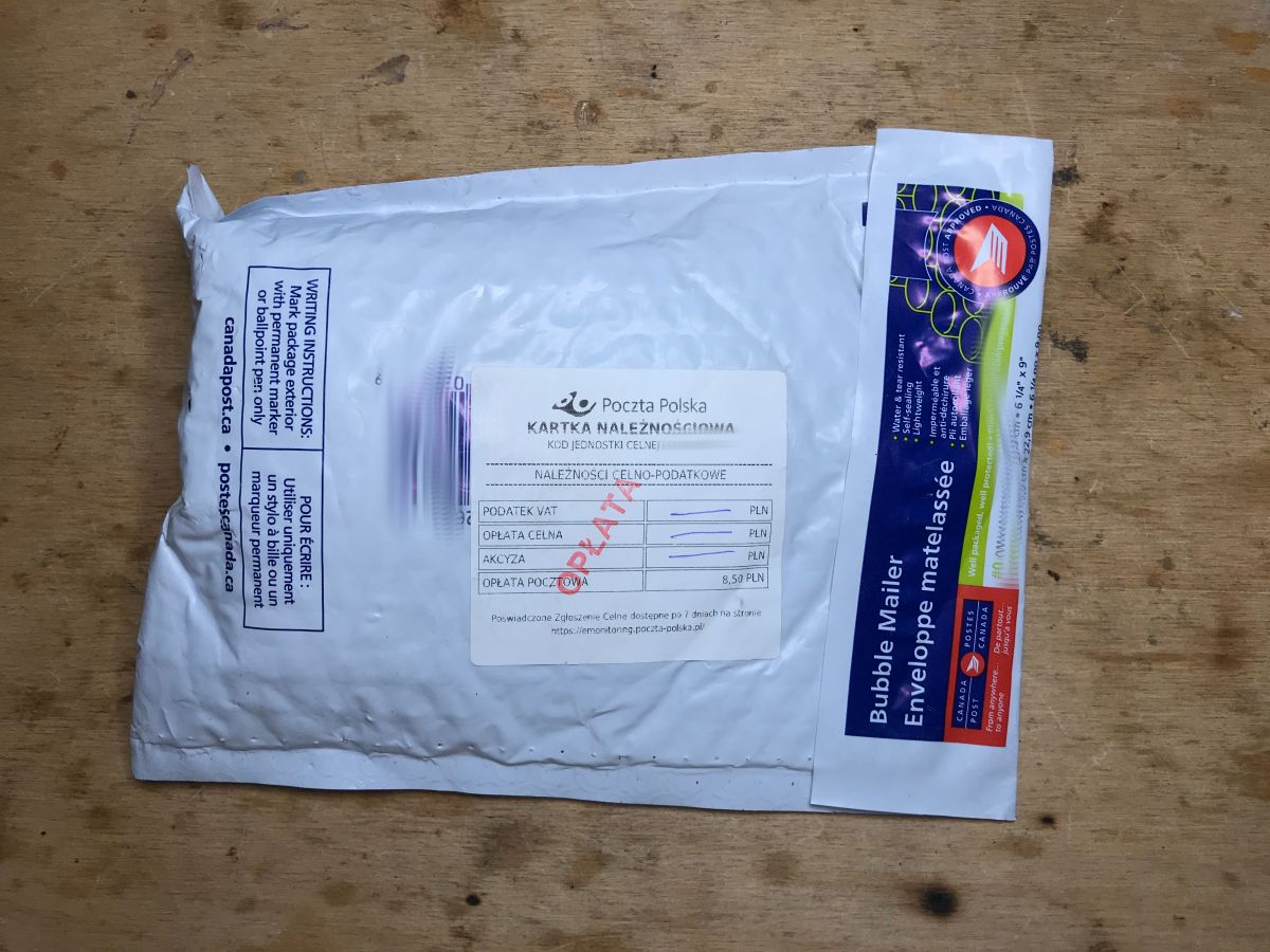
The Polish Post Office could not let it pass - even though it was marked as "Gift" - and counted the postage to some 8.5 PLN, which I paid upon receipt (the lady from the post office brought a package to the door at least):
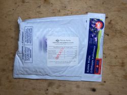
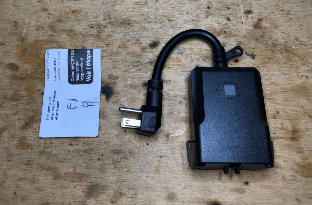
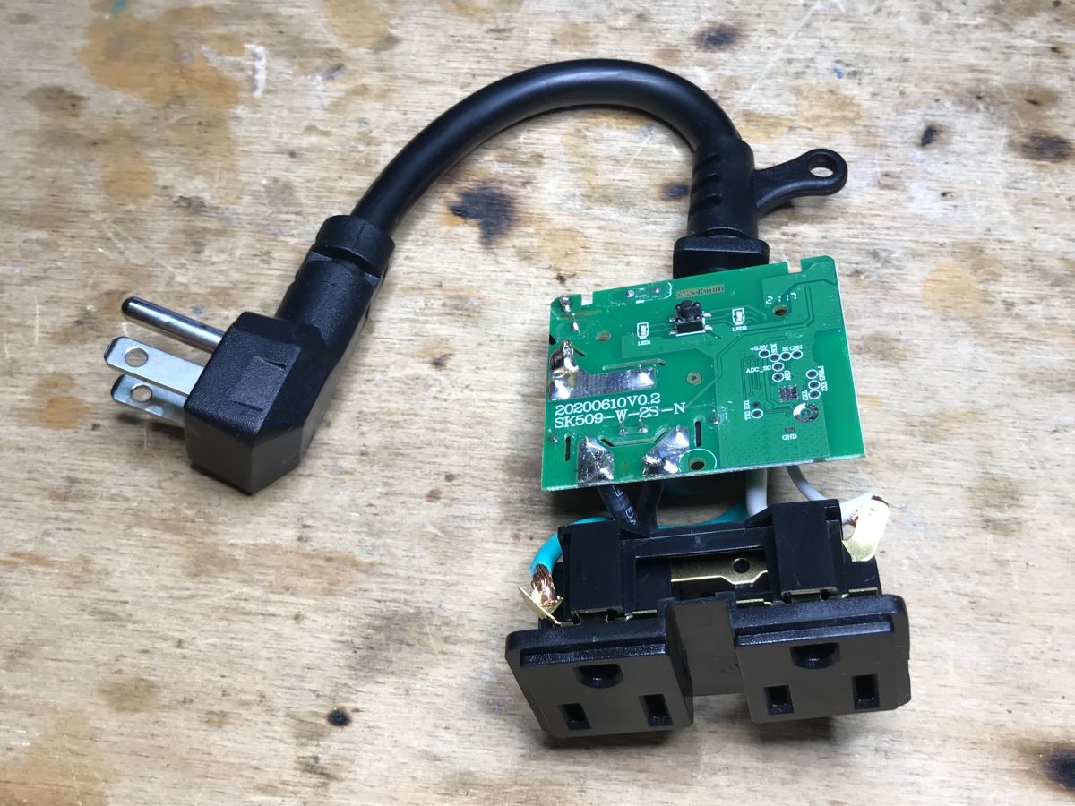
Kit Contents:

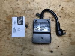
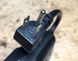
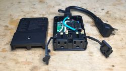
Well, in Canada they have a different standard of sockets than ours. The device is on 120V. I think that 230V would also work, but you need to check it after opening (check the parameters of all elements and their catalog notes, from the inverter controller as there is, through capacitors to relays).
The housing is screwed together with screws.
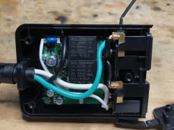
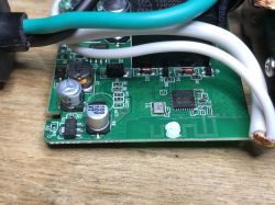
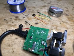
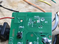
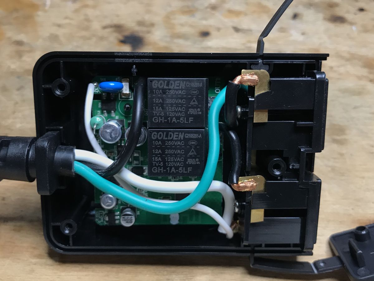
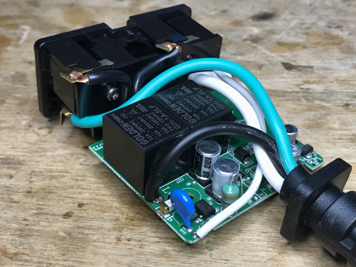
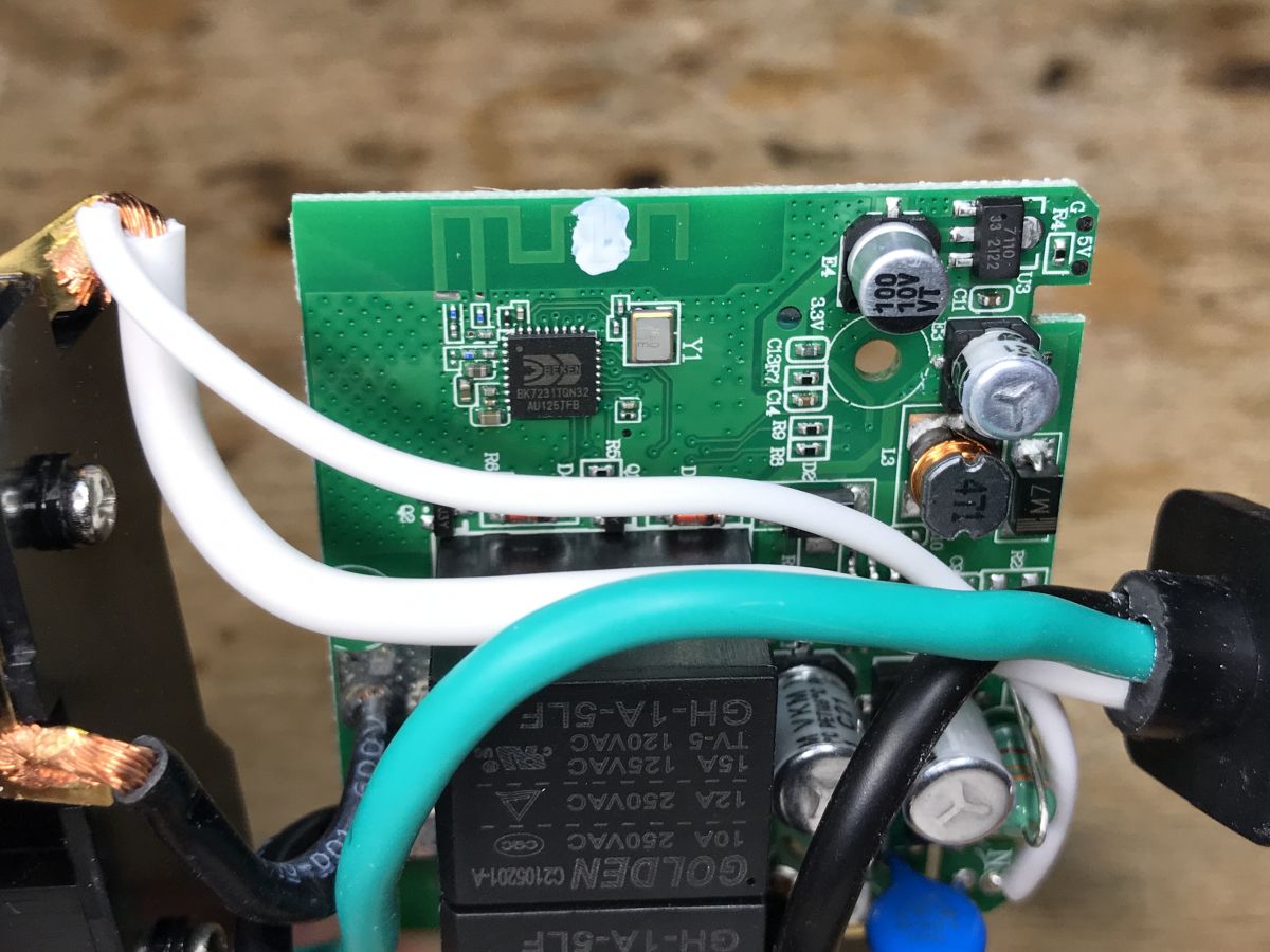
Inside we have two relays, one button and a 32-bit microcontroller with WiFI BK7231T, but simply placed on the main PCB of the device, not in the form of a module such as WB2S or WB3S:
There is a fuse at the input, a varistor, a simple filter on the choke:
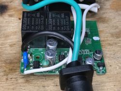

The power supply itself is transformerless - based on the ICW4008.
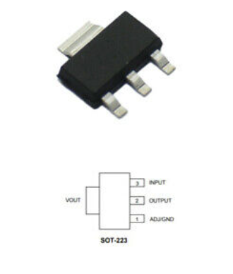
BK7231T - we will program it. Right next to it you can see the voltage regulator 3.3V, because BK works at 3.3V and the relay works at 5V (sometimes at 12V).

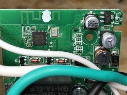
You can also see two transistors that control the relays.
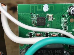
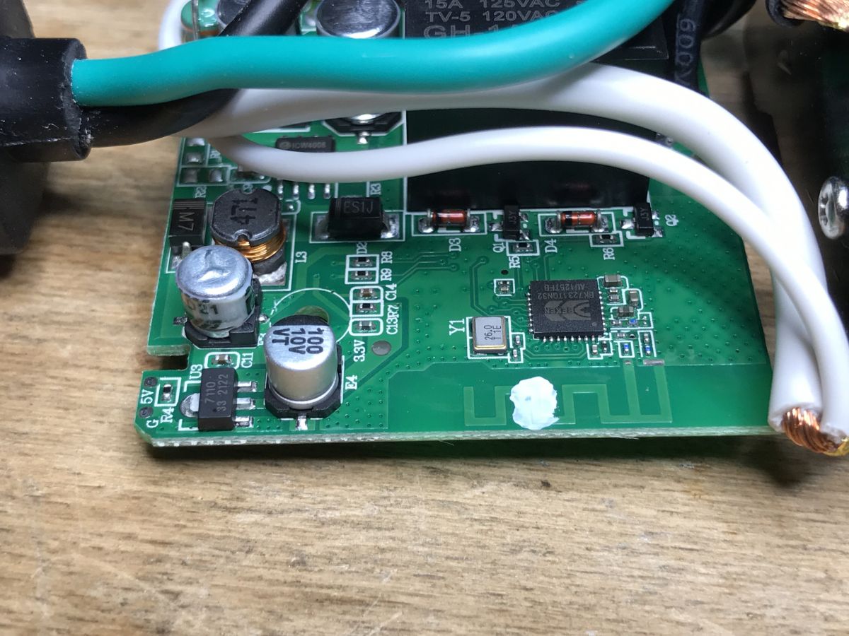
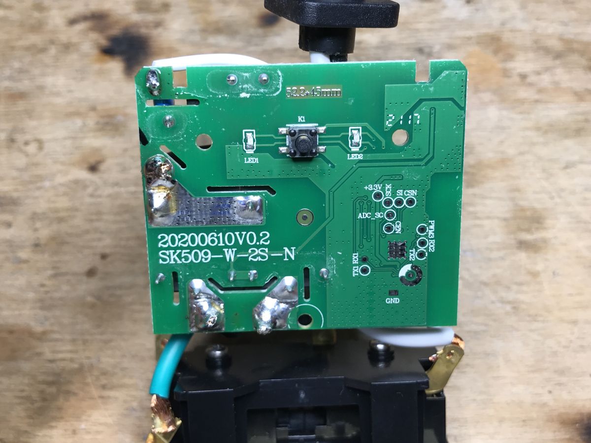
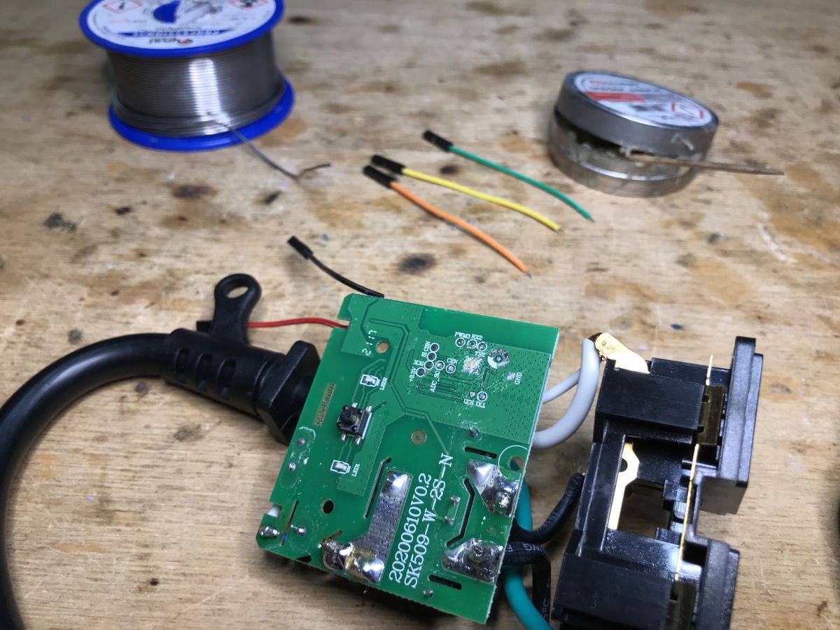
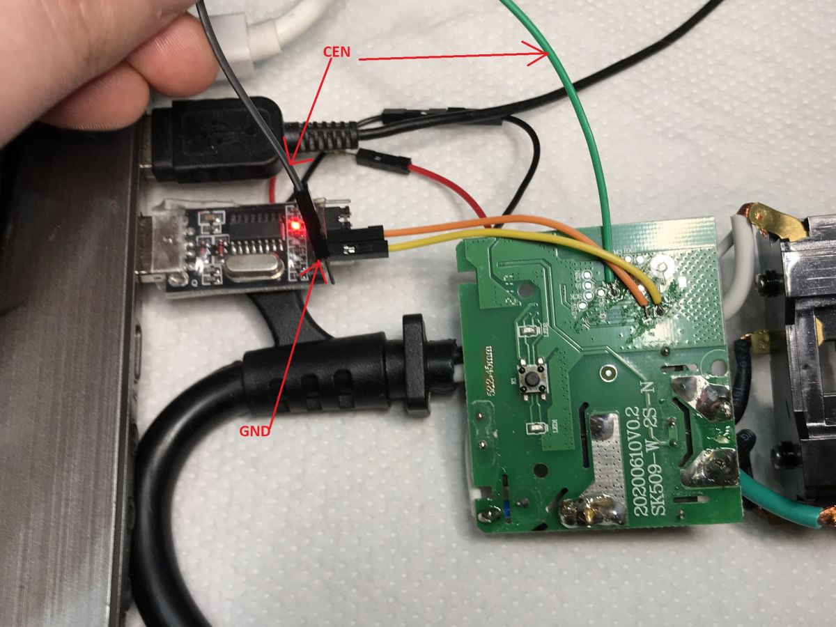
From the bottom, we have prepared pads for programming signals, including:
- UART1 port (programming via bootloader)
- UART2 port (debug log output with information about what the device does)
- SPI pins (programming if bootloader fails)
- CEN pin (system reset)


That's it - in the next paragraph we solder and program.
Programming BK7231T with my firmware
We download the last batch binaries and BKwriter 1.60 from my repo:
https://github.com/openshwprojects/OpenBK7231T_App
https://github.com/openshwprojects/OpenBK7231T
All operations are performed after disconnecting the product from the electrical network.
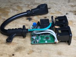
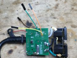
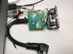
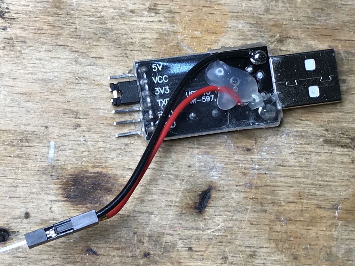
We connect the power from USB to LDO, pinout LM1117, 5V to VIN, ground to ground:

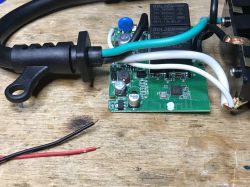
We isolate the wires, whiten them, give a little flux to 1117:
We solder (with a clean soldering iron tip! We clean e.g. with a sponge method):
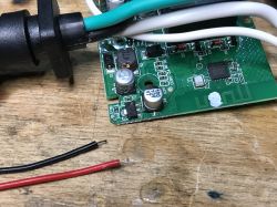
Same for 1RX, 1TX and CEN. The 2TX 2RX port is only a debug log output, we don't need it if everything is ok:
Before soldering, we also whiten the pads, we also apply flux, we also whiten the ends of the wires (previously isolated).
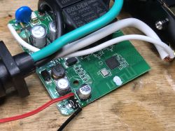
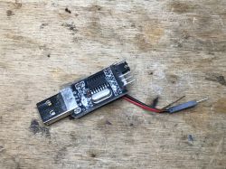
Connect the USB UART converter, here the HW-597 USB I like is TTL, in the 3.3V mode (jumper between VCC and 3V3), along with the power supply derived directly from the USB (it will not work from the pin signed 5V because it has a slightly different role):

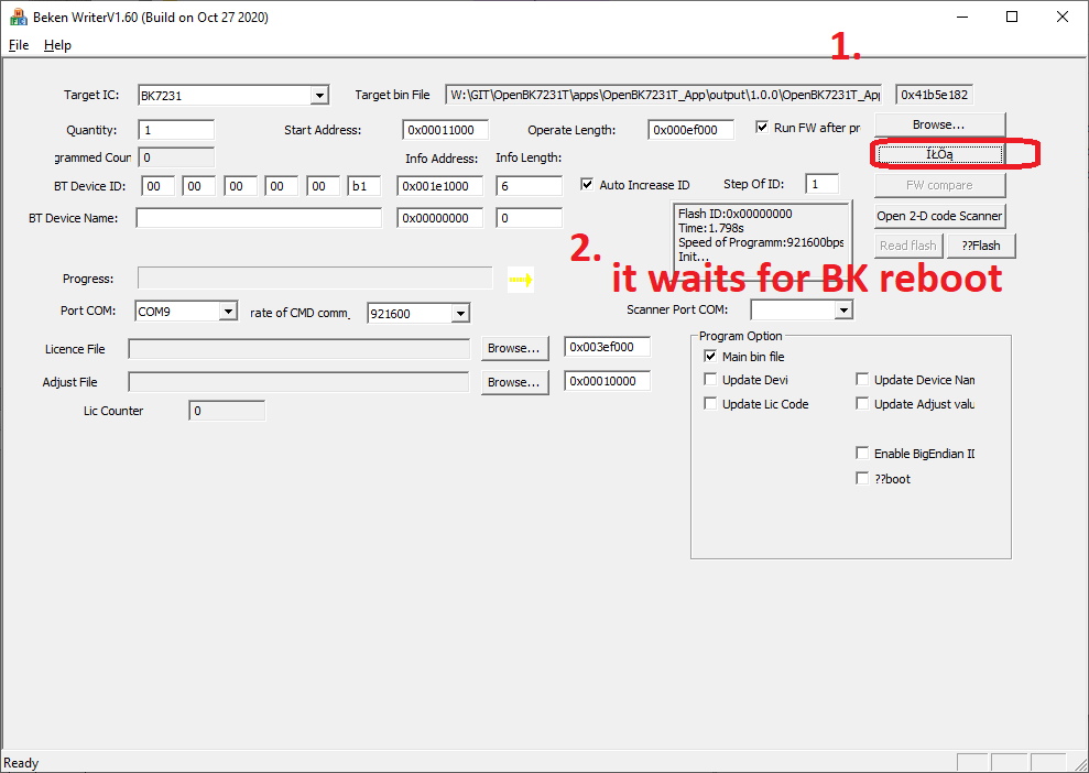
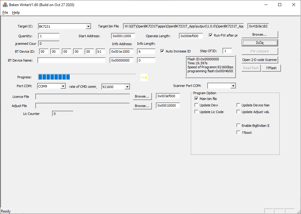
We run BKwriter 1.60.
We can make a copy of the original batch (Read button), programming is done in the same way, we just first choose what batch we want to upload.
So, we choose what batch we want to upload (here, select the UA versions) and start programming (actually, we start waiting for BK booting):
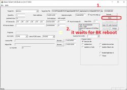
Now, as long as BKwriter is actively waiting for the BK boot signal, temporarily connect CEN to ground (here it is just on the USB dongle pin), literally for a second:

Only then did the actual programming begin:

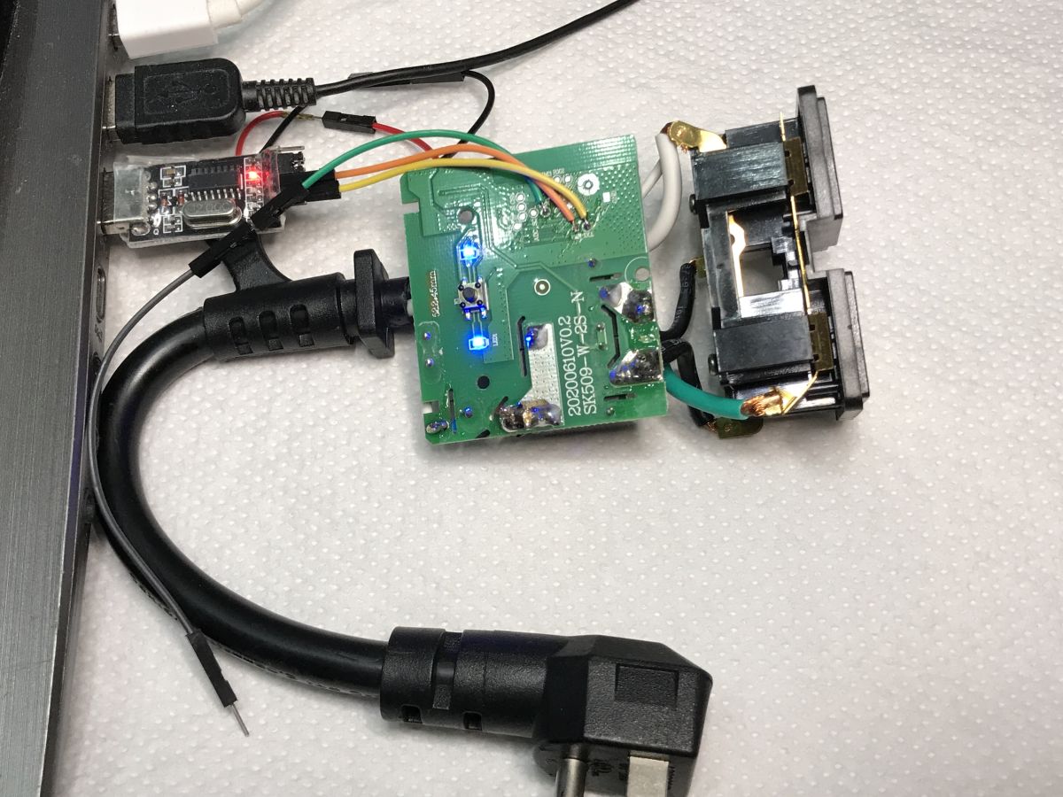
Programming Success:
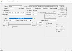
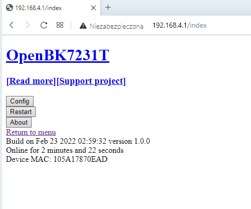
The BK access point is already visible:
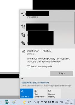
We connect to the WiFi point created by the BK7231T.
Here you may need to set our WiFi to a rigid IP, e.g. 192.168.4.10, in case DHCP does not work:
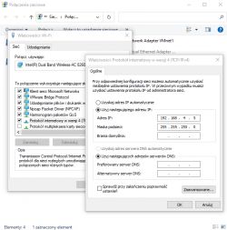
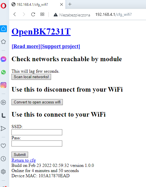
We open the page 192.168.4.1:
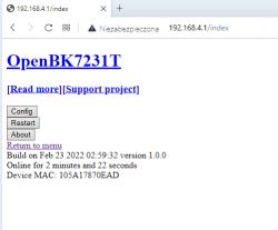
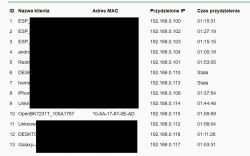
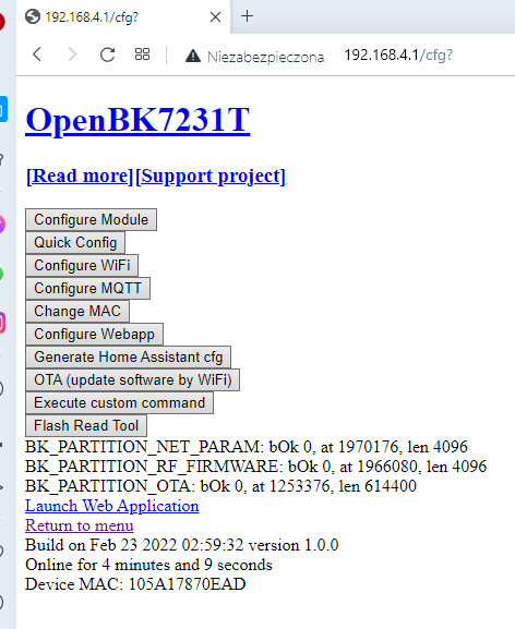
In Config, we set what we need (e.g. information on our home WiFi):
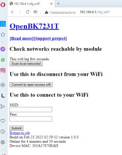
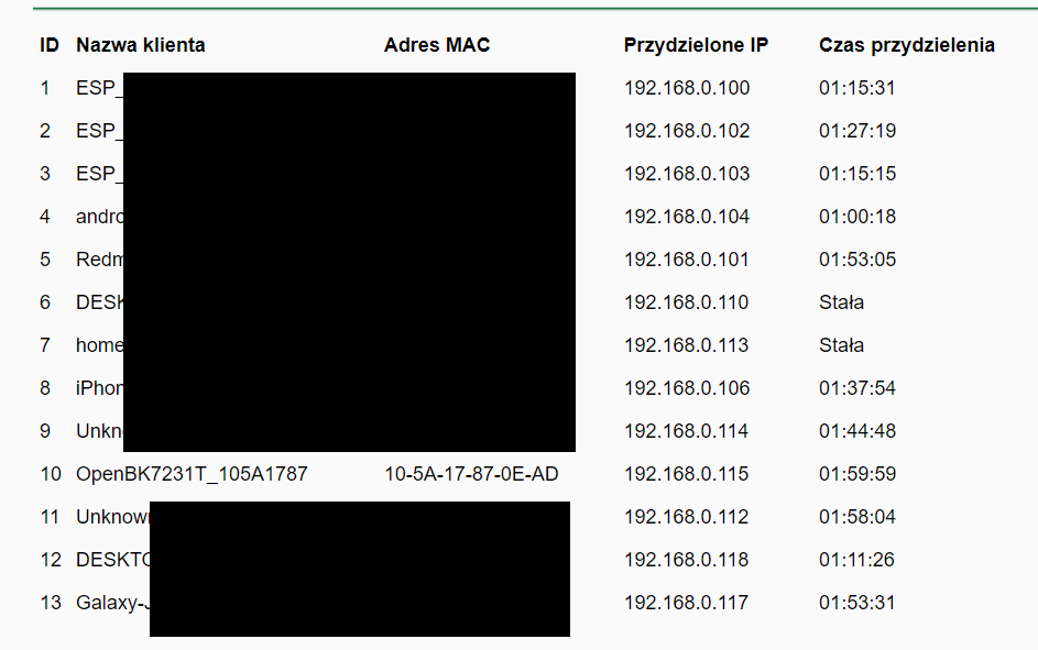
After setting the bearings on our home WiFi, we reset the system. You may also need to disconnect the power supply temporarily or wait a minute for the device to join our network. Its new IP can be found on our router in the list of DHCP clients:
 Pin role configuration, templates and button support
Smart devices have different configurations of buttons, relays and LEDs. They can be connected to different pins of the microcontroller.
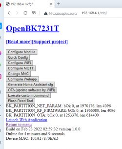
The "Configure Module" subpage is used to set the role of individual outputs:
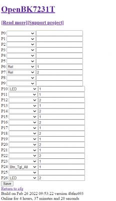
The left column is the role of the pin (button, relay, PWM) and the right column is the channel (individual relay number, PWM, etc).
You can learn the roles of the pins experimentally or by following the connections on the board.
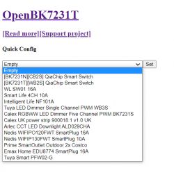
Some devices have already been developed by me, so there are ready-made configurations for them - they are in the "Quick config" tab:
The device of this theme is quite unique in that it has two relays and one button. In the original batch, the relays can be controlled separately, but only from the Tuya application level. The button either turns them on or off. To this end, I introduced the pin role: "Button Toggle All", which allows one button to disable / enable all channels of the fixture.
Connecting to the Home Assistant
Ultimately, my batch allows you to control any device of this type via MQTT - I recommend reading the "configure MQTT" and "generate Home Assistant config" tabs. Operation is analogous to Tasmota.
More information
More information about the batch and project can be found on the official repository:
https://github.com/openshwprojects/OpenBK7231T_App
Summary
Programming this WiFi-controlled splitter would not be possible without my batch. There are no alternative firmware for BK7231T, and conversion to ESP is not an option, because here there is no WiFi system dedicated to a module such as WB3S, that it can be converted to ESP12F, only everything is on one PCB. It would be difficult to connect the module loosely there and such a "sculpture" would not be profitable anyway.
After all, the whole conversion was easy - to upload my batch, just solder the cables, run BKwriter 1.60 and it's ready.
Finally, I would like to emphasize that the procedure described here works for BK7231T and modules based on it, i.e. WB2S, WB3S, etc.
For BK7231N (N version, not T version) the procedure is slightly different from what
I described here .
There is also the matter of a single button - one button for both relays. Especially for this device I implemented a role in the pin configurator ("Button Toggle All"). It's a bit strange that since the manufacturer gave two relays, he did not try to put two buttons ... but maybe it's because at least one button is necessary to force pairing with Tuya (although I have already seen smart devices where pairing turns on without buttons - by quick power on / off).
Now I think that this button could be used even better - each click could switch the combinations of relays to the next (two relays give 4 possible combinations on off), or e.g. a short press could switch the first relay, and a long (or double) the second. Perhaps I will add it in future code revisions ... I recommend following my repository on Github.
As for the alleged "outdoor" quality of the product, I wouldn't expect much. It should definitely be under a canopy, and probably with time the moisture itself will hurt it.
PS: Such a curiosity - I can see that this product (CCWFIO232PK) appears on the Tasmota website as "no longer supported" because previously there was an ESP module inside, and now there is Beken:
https://templates.blakadder.com/prime_CCWFIO232PK.html
Well, after my intervention, the product is 'supported' again - but this time it's because of my firmware. 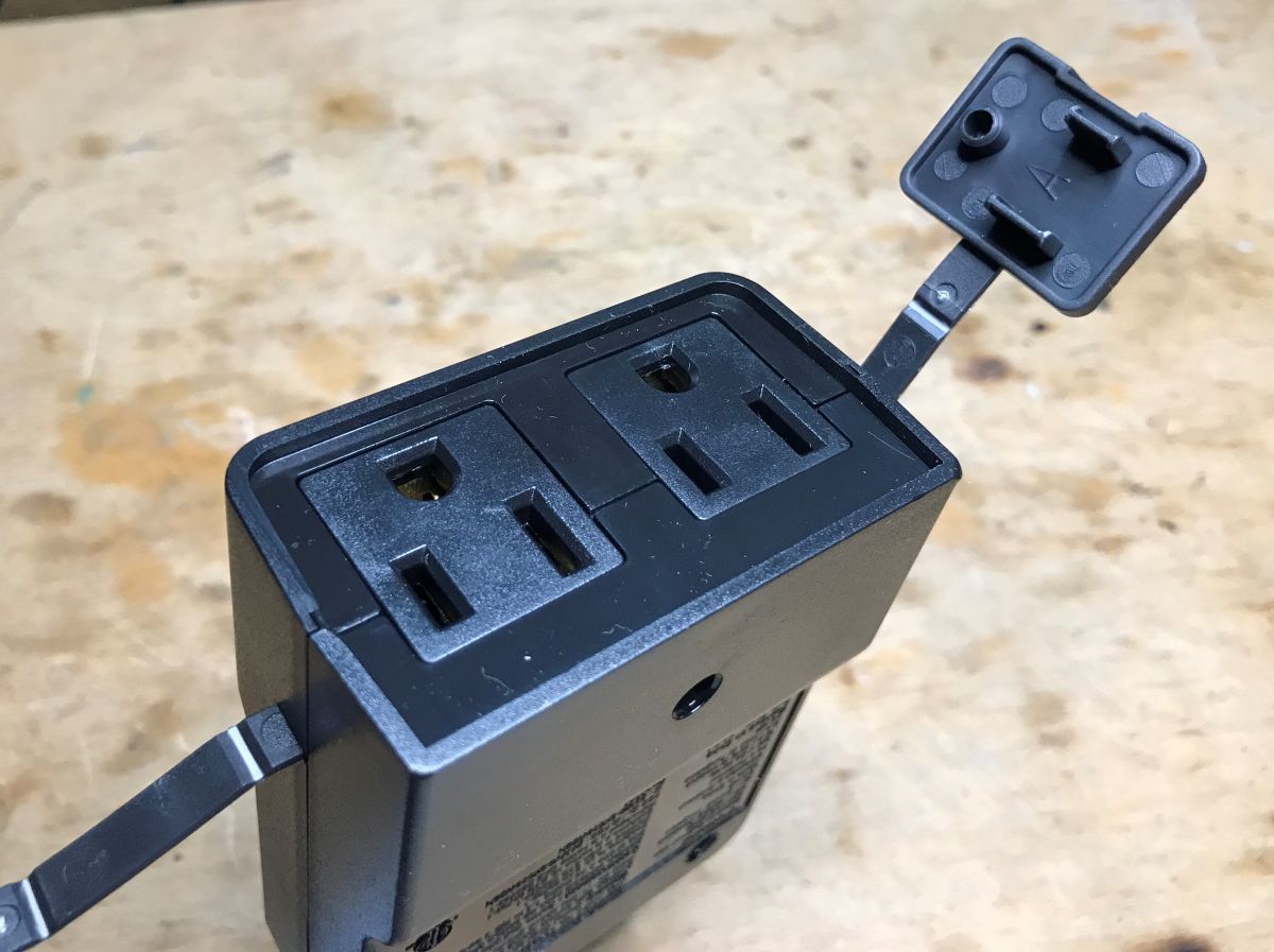


Comments
Can I upload a Tasmota code? The above manifesto is somewhat unclear. [Read more]
I meant that in CCWFIO232PK there was initially a module with ESP8266 and it was possible to upload Tasmota. Then the manufacturer (in line with the trend) changed ESP to BK7231T, so of course Tasmota... [Read more]
What exactly trend it comes? :) Added after 1 [minutes]: Also on ESP32-C3. It is worth getting acquainted with the offer of AI-Thinker and other manufacturers in order to look at the home... [Read more]
I do not know how much you are interested in Tuya and the products from their stable, but more and more "smart" toys, relays, light bulbs, door opening sensors, flood sensors, were initially built on ESP8266... [Read more]
Maybe this is it? ;) https://github.com/arendst/Tasmota/discussions/13761 [Read more]
I can see that there is some interest in movement with ESP32, but is it possible to find it in a finished Tuya product, and not buy it separately and solder it? But overall that's not what I meant.... [Read more]
Tasmota is not only MQTT and relay control, but also support for many sensors and activators. https://github.com/arendst/Tasmota/releases/tag/v10.1.0 [Read more]
I hope that over time (and with the support of possible contributors - anyone can add their changes to the repository, the so-called pull request, this is what open source is all about), support will also... [Read more]
Tasmota/ESPHome work for ESP32 and ESP8266. This is an open firmware (somewhat similar to tasmota) for beken 7231t and 7231n which a lot of newer devices are using instead of ESP based chips. [Read more]
Small update. I added ability to control two separate relays with single button. This is very useful for devices like the one from this topic (CCWFIO232PK). Single click = toggle relay 1. Double click... [Read more]
Hey, I just want to send a huge THANK YOU! This is fantastic, well written and very detailed :) I will definitely be upgrading the firmware on my devices. [Read more]
Thank you for this awesome guid. I managed to use this guide to Bekenize an AU Deta Double Power Point Wall Outlet https://obrazki.elektroda.pl/2789424600_1656890909_thumb.jpg I had to do trial... [Read more]
Create a pull request on github repo. But soon we are moving to more flexible, online devices database that will be available through javascript app and always automatically updated [Read more]
Done. I would love to help with improving the styling of the HTML pages. Is there a way to test the server without running on a chip? [Read more]
That's a great, I would really like to see improved HTML pages. There was a windows build but it's not maintained anymore. I could fix it, but you should be aware that adding a very large piece of CSS... [Read more]
How large are we talking? can you estimate it in byte size? I could add a very small amount of css to make it look nicer. Or use a minified javascript to style it on-the-fly on the browser rather than... [Read more]
I did quick makeover of the html pages for OpenBK7321T_App. I added 1,474 bytes worth of CSS. I have tested it with TYWB3S chip and it seems to run fine. I will add a pull request. https://obrazki.elektroda.pl/2347247800_1657109925_thumb.jpg... [Read more]
Very nice style, altough it reminds me of a certain firmware... anyway, is CSS in the separate file? I think that putting CSS in separate file might be a good idea, because this might allow browser... [Read more]
No it is in the code but good idea. I will work on seperating it into a file. It does look like a certain firmware. I can do a quick change over. Maybe I will go with light theme! [Read more]