Hello.
This time analog retro. The AM receiver on the basis of the article from
Young Technician from the 1980s. Radio to receive "Polish Radio Program I" on long wave, at 225kHz.
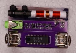
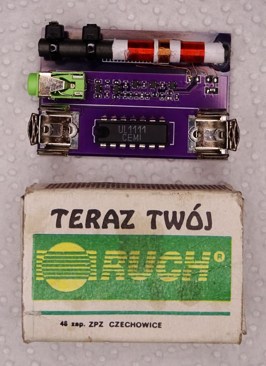
The UL1111 radio is the first chip I have assembled. It was a "RADIO HOBBY" set bought around 1990.
In the presented UL1111 receiver I replaced with BC847CW transistors. To make it not too easy, the smallest size elements I had, SOT323 and 0402.
I used headphones from
walkm ... phone. By means of jumpers on the underside of the PCB, the headphones can be set to be connected in parallel or in series.
The whole is powered by a 1.5V cell.
Reception like reception, the radio is heard loud enough. By the way, you can listen to converters in the computer, light bulbs and other equipment

.
It's best to keep your distance from all modern electronics.
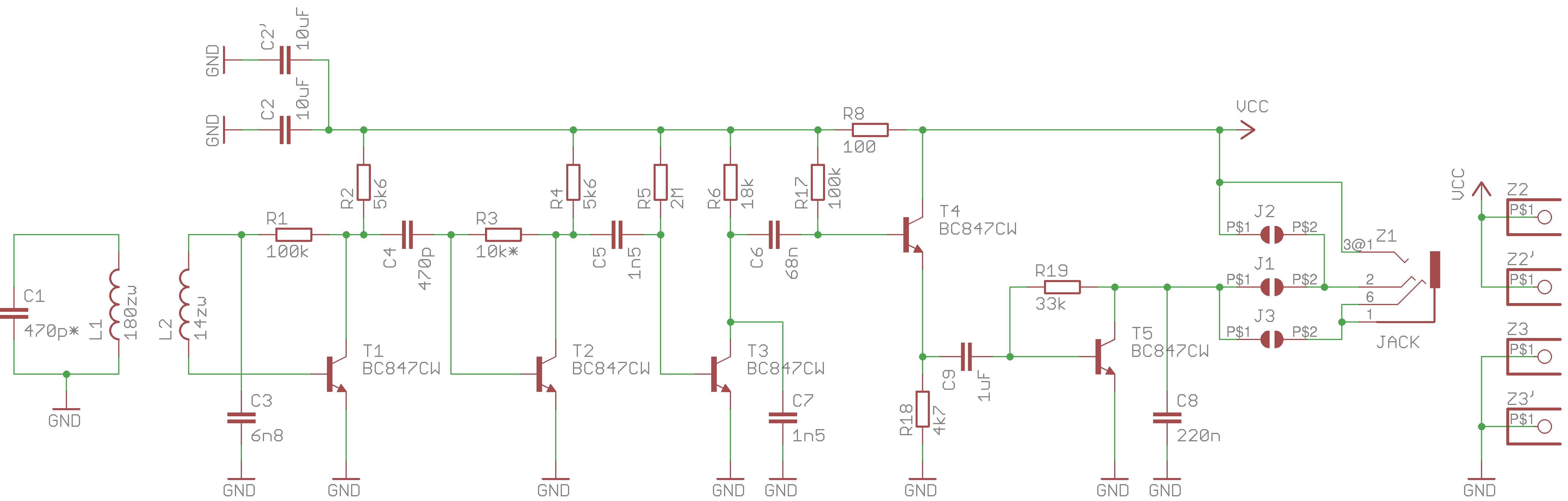
Diagram: 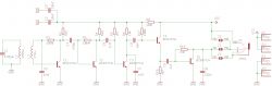
I have kept the original item numbering, so you can read the exact description in the article from the link.
PCB: 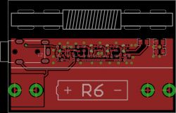
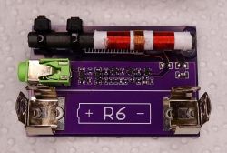 Antenna
 on ferrite with ...:

Ferrite dimensions: 5mm x 50mm
L1: 20mm wide, 0.1mm wire
L2: 17 turns, 0.15mm wire
Ferrite probably from the Neptune monitor. It lay in junk for over a quarter of a century.
0.1 wire from the choke from TV Lazuryt. Also 25+ So that retro antenna. :)
Antenna on ferrite from "DCF" (including: WVB-0860N-03A):
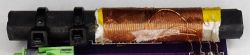
Ferrite dimensions: 8mm x 60mm
L1: 25mm wide, 0.15mm wire
L2: 14 turns, 0.15mm wire
Between the ferrite and the PCB, I put a laminate pad on one side and fastened the whole thing with cable ties.
Thanks to this, you can freely move the coil along the ferrite.
Tuning L1: Wind the antenna on a non-tightly rolled (so that it can be moved) piece of paper.
We wind a little more turns. If the strongest reception is when the coil protrudes from the ferrite, then we have too many coils (unwind a few and check again).
How it picks up in the middle is not enough. We aim with the number of turns so that the strongest reception is between the center and the edge.


Comments
The first picture confuses this chip. I made a lot of research about where to find it in the diagram and where all the additional individual transistors come from ... It would better make sense of something... [Read more]
I put for a size comparison. Ordinary 2 * 16?. UL1111 sounded quite quiet from what I remember, although I don't know if it was a matter of headphones or boot errors. Anyone have a schematic... [Read more]
Perhaps it is the same diagram as in MT, there was even an implementation on the electrode https://www.elektroda.pl/rtvforum/topic3100861.html It's probably in a detector radio with no power... [Read more]
I've been thinking about this radio for several years now. I remember when a friend made one in the 80's - then it was something! So, after more than 30 years, I wanted to do it myself. But I... [Read more]
Kind of retro - and the modern, beautifully made tile definitely gives it the charm of its second youth :) I remember that 30 years ago I tinkered with a little radio from Wojciechowski's book "Modern... [Read more]
The basic problem is that our country is always run by short-sighted idiots. We used to have one of the strongest radio stations in the world with the world's tallest mast in Konstantynów. You could... [Read more]
Probably not the same scheme but a similar idea. https://obrazki.elektroda.pl/9416525400_1664797371_thumb.jpg https://obrazki.elektroda.pl/7728801100_1664797371_thumb.jpg https://obrazki.el... [Read more]
You mean medium waves? LW and MW transmitters are disappearing because they are uneconomical. AM modulation is very energy inefficient and low quality of the presentation. How many audiences are currently... [Read more]
Yes, but I was talking about the situation 30 years ago. 7 years of building a new broadcasting center, which was completely pointless ... [Read more]
Initially, it was supposed to be on UL1111, I also combined something with TA7642, I even bought THT capacitors / resistors (SMD is in abundance with us). In the end, I opted for transistors (I also bought... [Read more]
Do you have any bad experiences with this scalak? In my opinion, it works like any other radio. In total, for over 25 years I have made a dozen (AM and FM), from detector, tube and transistor ones, through... [Read more]
It was waking me up, but it was probably the antenna's fault. I have to check on the new one again. What can you pick some smaller ferrites from? (5mm * 50mm) Any chokes or something? I searched... [Read more]
Older Dior receivers, turn-of-the-century "dachshunds". Available in olx or at a flea market at a ridiculous price. The ferrite rod can be easily shortened by cutting the groove with the dremel and breaking... [Read more]
I was thinking of something cheap and generally available like these DCF modules. It's a pity to break one radio to make another. [Read more]
Not. The point here is that the radios were designed to connect headphones with an impedance of 100-400?, with an impedance of headphones of the "Walkman" type, probably 32?, and people were looking for... [Read more]
What were they supposed to design here? The handset is in series in the collector circuit and behind. The lower the resistance, the more power and the stronger the sound. A resistance of 32 ohms is approximately... [Read more]
Ya ... and what is the voltage drop at the CE connector even of a saturated transistor? [Read more]
Tia, the power on the transistor at 50 mA and Uec = 1.5 V is 75 mW, the catalog Ptot for a single transistor is 300 mW. The voltage Uec contributes to the collector current drop in a directly proportional... [Read more]
When connecting two channels of headphones in parallel, the resultant impedance is 16ohm, but you can connect in series - i.e. connect the jack between R and L without ground - then the situation is b... [Read more]