Hello.
This time analog retro. The AM receiver on the basis of the article from Young Technician from the 1980s. Radio to receive "Polish Radio Program I" on long wave, at 225kHz.
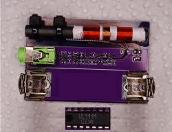
The UL1111 radio is the first chip I have assembled. It was a "RADIO HOBBY" set bought around 1990.
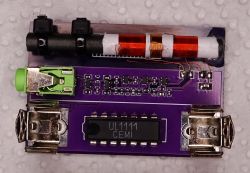
In the presented UL1111 receiver I replaced with BC847CW transistors. To make it not too easy, the smallest size elements I had, SOT323 and 0402.
I used headphones from
The whole is powered by a 1.5V cell.
Reception like reception, the radio is heard loud enough. By the way, you can listen to converters in the computer, light bulbs and other equipment
It's best to keep your distance from all modern electronics.
Diagram:

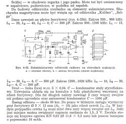
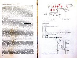
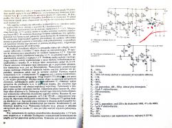
I have kept the original item numbering, so you can read the exact description in the article from the link.
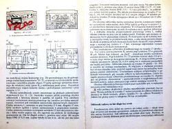
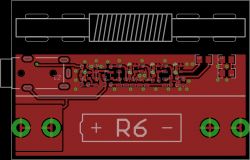
PCB:
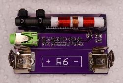
Antenna on ferrite with ...:
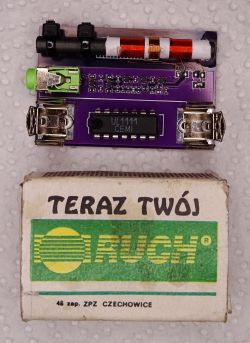
Ferrite dimensions: 5mm x 50mm
L1: 20mm wide, 0.1mm wire
L2: 17 turns, 0.15mm wire
Ferrite probably from the Neptune monitor. It lay in junk for over a quarter of a century.
0.1 wire from the choke from TV Lazuryt. Also 25+ So that retro antenna. :)
Antenna on ferrite from "DCF" (including: WVB-0860N-03A):

Ferrite dimensions: 8mm x 60mm
L1: 25mm wide, 0.15mm wire
L2: 14 turns, 0.15mm wire
Between the ferrite and the PCB, I put a laminate pad on one side and fastened the whole thing with cable ties.
Thanks to this, you can freely move the coil along the ferrite.
Tuning L1:
Wind the antenna on a non-tightly rolled (so that it can be moved) piece of paper.
We wind a little more turns. If the strongest reception is when the coil protrudes from the ferrite, then we have too many coils (unwind a few and check again).
How it picks up in the middle is not enough. We aim with the number of turns so that the strongest reception is between the center and the edge.
Cool? Ranking DIY


