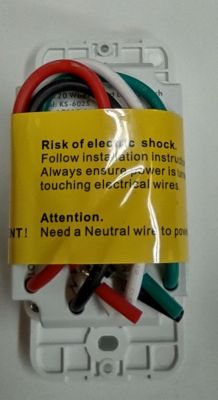
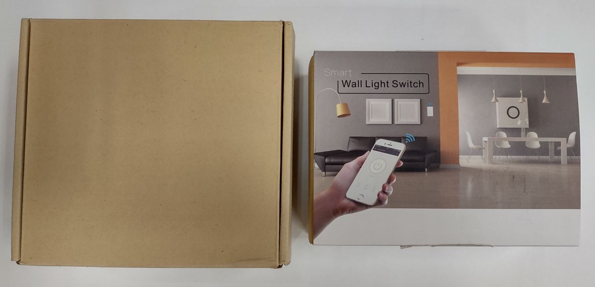
I have now successfully flashed 4 of these switches so it's time to provide the details. I have purchased switches from both Amazon and directly from Kuled. The box on the left is how they come from Kuled and the box on the right is from Amazon.

Amazon link -
https://www.amazon.com/Compatible-Requires-Ne...00a87a1346&ref_=pd_gw_ci_mcx_mr_hp_atf_m&th=1
Kuled link -
https://kuled.com/product/smart-wifi-light-switch-k36-4pack/
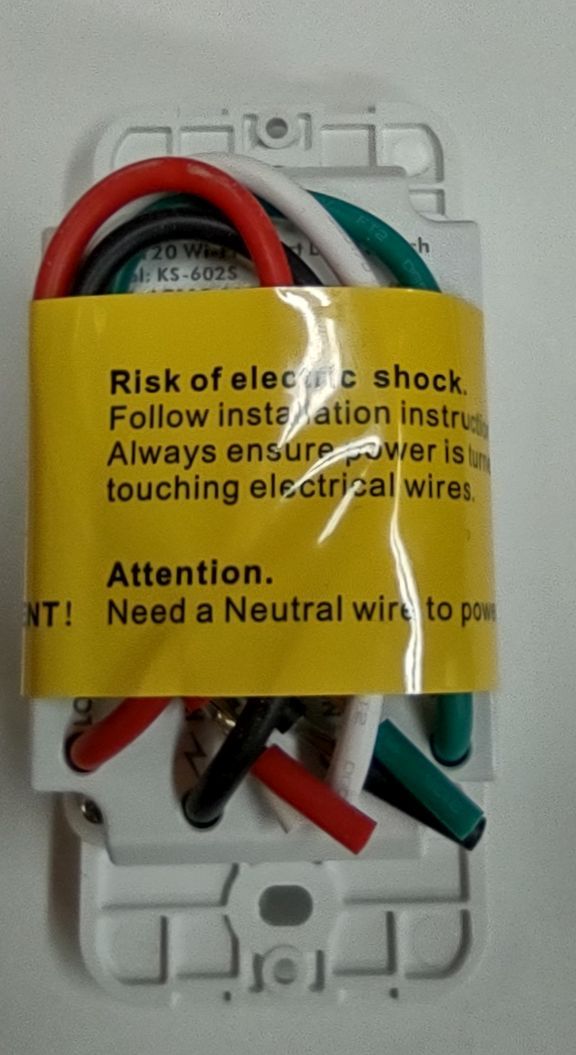
This is the front of the switch.

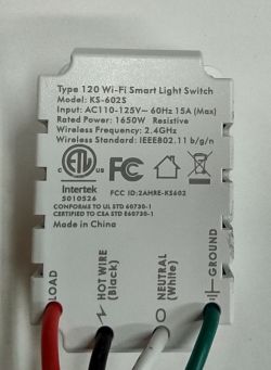
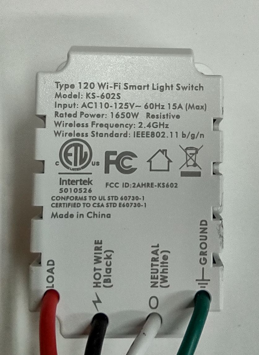
This is the back.
There seem to be a number of similar switches from other locations that all have the same model number - KS602-S although sometimes the switches are advertised as K36 - not sure what that's all about.
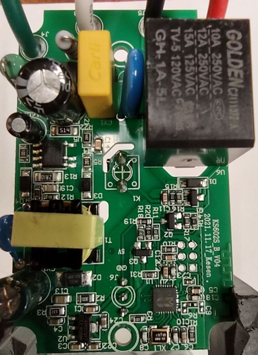
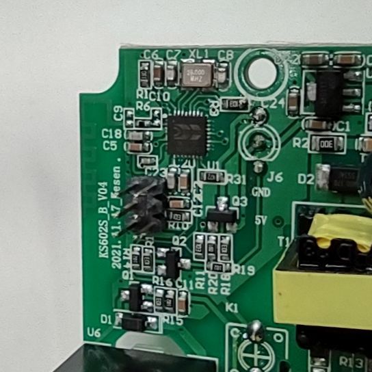
If you remove the 4 screws you see the back of the PCB.
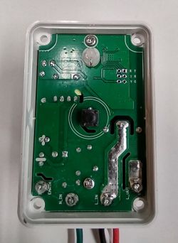
Then if you remove 2 more screws you get to the top of the board.

There is a 2 X 6 X 2mm PCB hole layout that can be used for flashing. The first switch I soldered wires to the holes but for the others I actually soldered in a 2 X 6 header and left the header since there was plenty of room.

The header labels refer to these pins on the MCU:
T - Transmit
R - Receive
G - Ground
R - CEN
I - No Connection
V - 3.3 volts
As usual the Transmit goes to Receive on the USB - Serial adapter and Receive goes to Transmit on the adapter. Make sure you are using a 3.3 volt adapter and connect V and G to the appropriate connections on the USB adapter. For the R terminal I used a single wire.
Once you are wired up and ready to go it's time to flash. I already had Python installed on my PC so I just installed hid_download_py and then moved the bin flash into the same directory as uartprogram. Once I had all that set up I opened the command line window and changed the default directory to the uartprogram directory and entered the flash command.
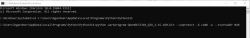
After pressing enter, I briefly touched the CEN pin wire to ground and the flash started. Once completed, I followed the standard procedure to log into the temporary access point and configure the WiFi settings. Then I determined the IP address assigned by my router and logged into the switch. It was then a simple matter to configure the correct pins as below:
P17 - Relay - channel 1
P24 - LED - channel 2
P26 - Button - channel 1
After saving these setting, I configured the MQTT settings and I was ready to go. I was able to control the switch via MQTT through my home control system and was even able to set up device groups which greatly simplified setting up 3 way switches.
Well, that's about it. I am greatly impressed with the software and would really only like 2 additional features that Tasmota implements. I would like to configure a static IP without using router address reservation and it would be nice to configure 2 SSIDs, a main one and a fall back.
If anyone has any questions or needs more information or pictures, please feel free to ask.
Bob


Comments
Very good job, I'm happy it worked out for you. Your description is very detailed, so I will separate this post from the base thread and add it to our presentations/guides list. Yes, our Tasmota Device... [Read more]
This switch is for 110V 60Hz [Read more]
Horrible! Only you see, the Author is from the United States of North America, and there are other Mayan prunds. :cry: [Read more]
Our forum is multilingual. The English site is https://elektroda.com/ and there are English-language materials, and the Polish site is https://elektroda.pl/. Some of the materials are common and are translated... [Read more]
Where can I find the uartprogram? [Read more]
All links are here: https://openbekeniot.github.io/webapp/devicesList.html uartprogram is in "hid_download_py" but maybe you should try Windows exe UART flasher first? Or bkWriter 1.60? https://github.com/openshwprojects/BK7231GUIFlashTool ... [Read more]
I used the BK7231 Easy UART Flasher on my PC and successfully flashed the file: OpenBK7231N_QIO_1.15.384.bin. When the upload finished, I restarted the device and got the device AP. I pointed my browser... [Read more]
@mannsteve what kind of device do you have? What is in the serial log? Use TX2 pin with 115200 baud to see what device logs. EDIT initial test shows that 384 works for me, no surprises here.... I will... [Read more]
What are the MQTT commands to turn the switch on or off? [Read more]
To turn the switch on you would use "topic/1/set 1" To turn the switch off you use "topic/1/set 0" Without the quotes and topic is whatever name you gave the switch. Bob [Read more]
Thanks. That's what I thought watching the get command on MQTT explorer, but I can't control it with a publish. Is there a status command? I am connected to the MQTT broker or I wouldn't be able to publish... [Read more]
You are most likely using an older version (didn't do OTA to latest) and you didn't reboot device after changing MQTT topic? But.. I will just note that we also support Tasmota syntax, as said in project... [Read more]
You should also set the LED to 2 instead of 1 and you get individual control of the relay and the led. https://obrazki.elektroda.pl/1410732200_1674790876_thumb.jpg Bob [Read more]
Many thanks. The switch is now working using MQTT commands. Do you know how to add the switch to Home Assistant? [Read more]
Update to latest version and follow guide: See here for more information: https://openbekeniot.github.io/webapp/devicesList.html [Read more]
I just did this my first time using bk7231flasher v1.0.4. Considering it was my first, things went smoothly. Hardest part was finding the which signal was on which test point on the board, mine has no... [Read more]
LED_n is a negated LED Just don't set LED role for given pin, you can always set AlwaysHigh or AlwaysLow to force given state forever we are much more flexible than that. You can just set relay... [Read more]
Thanks for the info. Everything except being able to see a button press is resolved. BTW, there is no way to turn off the red LED. You mention an autoexec.bat file, something I have not heard in many... [Read more]
After doing "Erase all" you should restore RF partition in Web App -> Flash Tab. The autoexec.bat can be created in Web App -> FileSystem Tab. What do you mean with "see button press"? A log message?... [Read more]