Teardown of
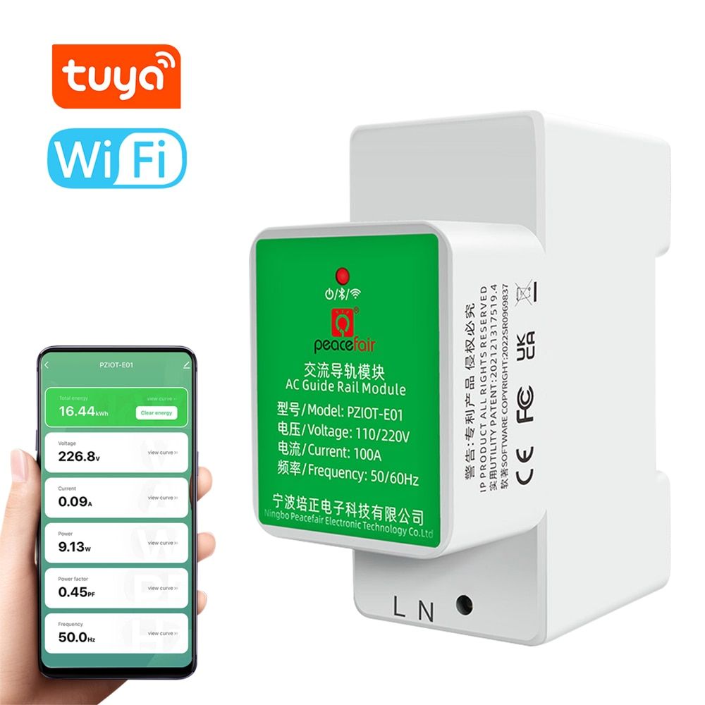
this energy meter from AliExpress.
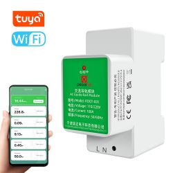
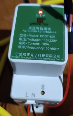
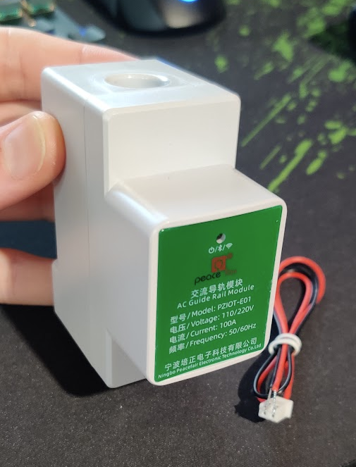
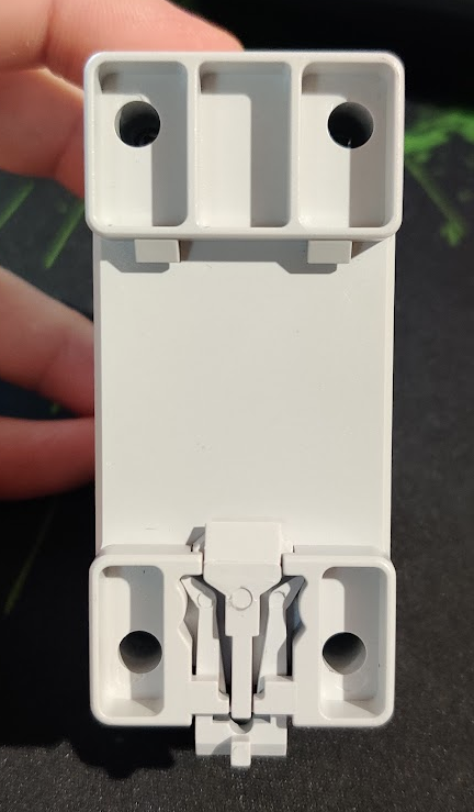
This device is an interesting DIN rail energy meter with a hole through the middle to pass a wire for metering. No physical connection of the circuit being metered is required. It's a unique design; instead of connecting a CT clamp to a metering device, the CT is inside the DIN module, so it keeps the circuit box tidy.

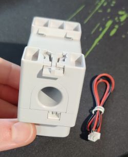
Opening the device is very simple, just 4 screws on the back:

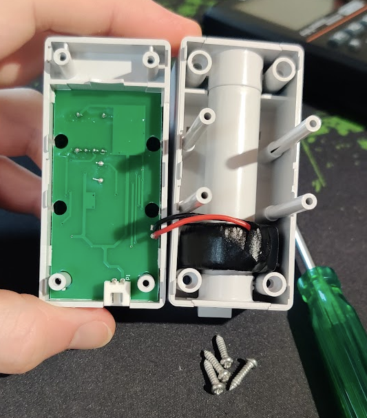
We can see the CT wrapped around the through-hole. Accessing the circuit board is quite a hassle; there are no screws holding it in place, it is secured by the 4 plastic clips you can see at the 4 corners of the board:
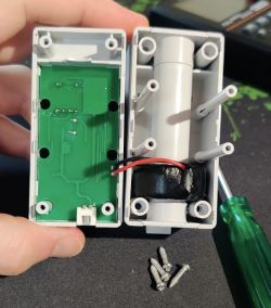
It's obviously designed to be assembled, but not disassembled. It was very difficult to get out from the clips, I ended up using a blade to shave away one of the clips at the corner, and then when lifting that one corner out, I was able to wiggle it free from the remaining 3 clips.
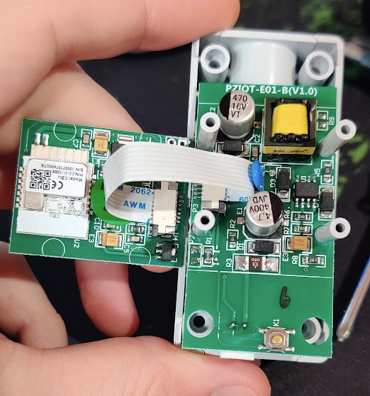
Now we can see there are 2 boards inside. The wifi board is connected to the power electronics board by a little ribbon:
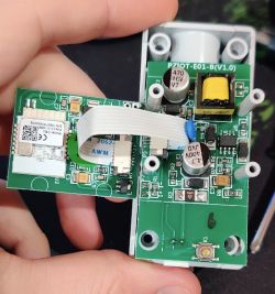
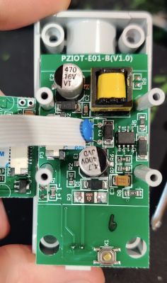
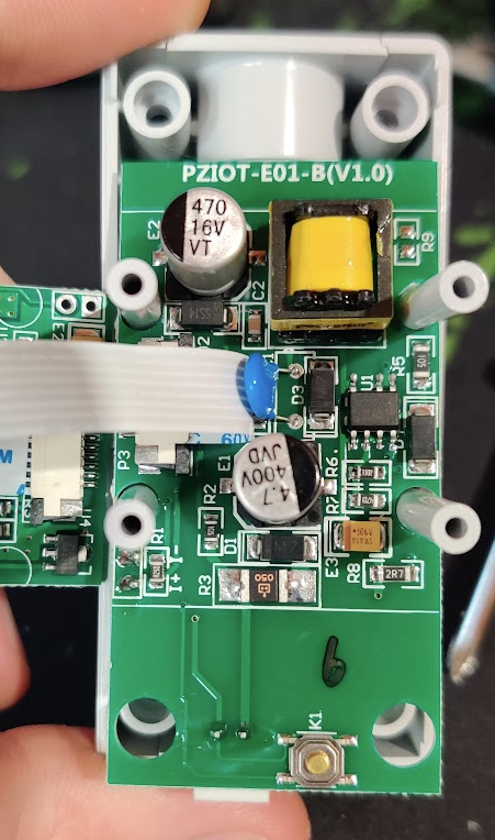
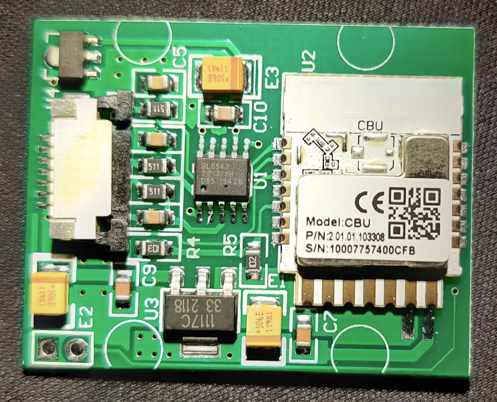
Closer look at the mainboard:
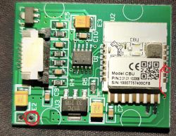
And I disconnected the ribbon to have a closer look at the little daughterboard:

It's running a CBU and BL0942 for metering.
The BL0942 is NOT connected with RS232, it seems to be connected by SPI instead.
Flashed OpenBK with no problem using the command:
python uartprogram ./OpenBK7231N_QIO_1.15.152.bin --unprotect -d com7 -w --startaddr 0x0
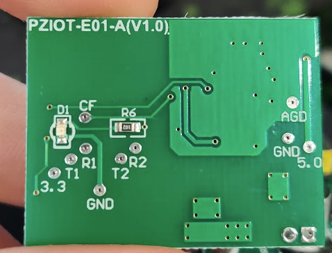
The pinouts I could trace:
P9 - BL0942 - CF1
P14 - BL0942 - SCLK_BPS
P16 - BL0942 - RX/SDI
P17 - BL0942 - TX/SDO
P20 - Bluetooth button
P22 - Status LED
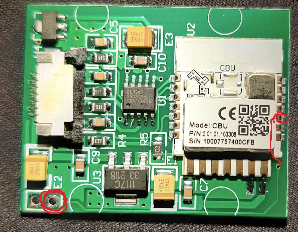
P28 - ??? E2 Via
There is a button on the device with the bluetooth logo next to it:
I guess this button will put it into discovery mode with stock firmware. It is connected to P20, and I'm not sure how to make this work in OpenBK? I guess it should be configured that a long-press might perform a factory reset, or go into some wifi discovery mode without wiping other config data.
Alternatively, if OpenBK ever supports something like a quick local-read feature pairing with a nearby bluetooth device and run an app for a quick local reading?
There is also an LED on the front with POWER/BLUETOOTH/WIFI written next to it. It just seems to be a red LED that you can turn on/off, so stock firmware probably uses some flashing states to communicate different information. It would be nice for OpenBK to model some sort of "status" led, which could communicate various status details via flash patterns on a status led. Many devices have these, and it's never quite sure what to do with them. I usually just assign them wifi state, but that's not how the stock firmware uses these lights.
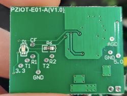
There is also one random track that leads from P28 to the big unpopulated VIA just below the E2 label on the circuit board... it doesn't go anywhere else. So P28 is not wired to anything, but it looks like the circuit design intended that it might be used for something.
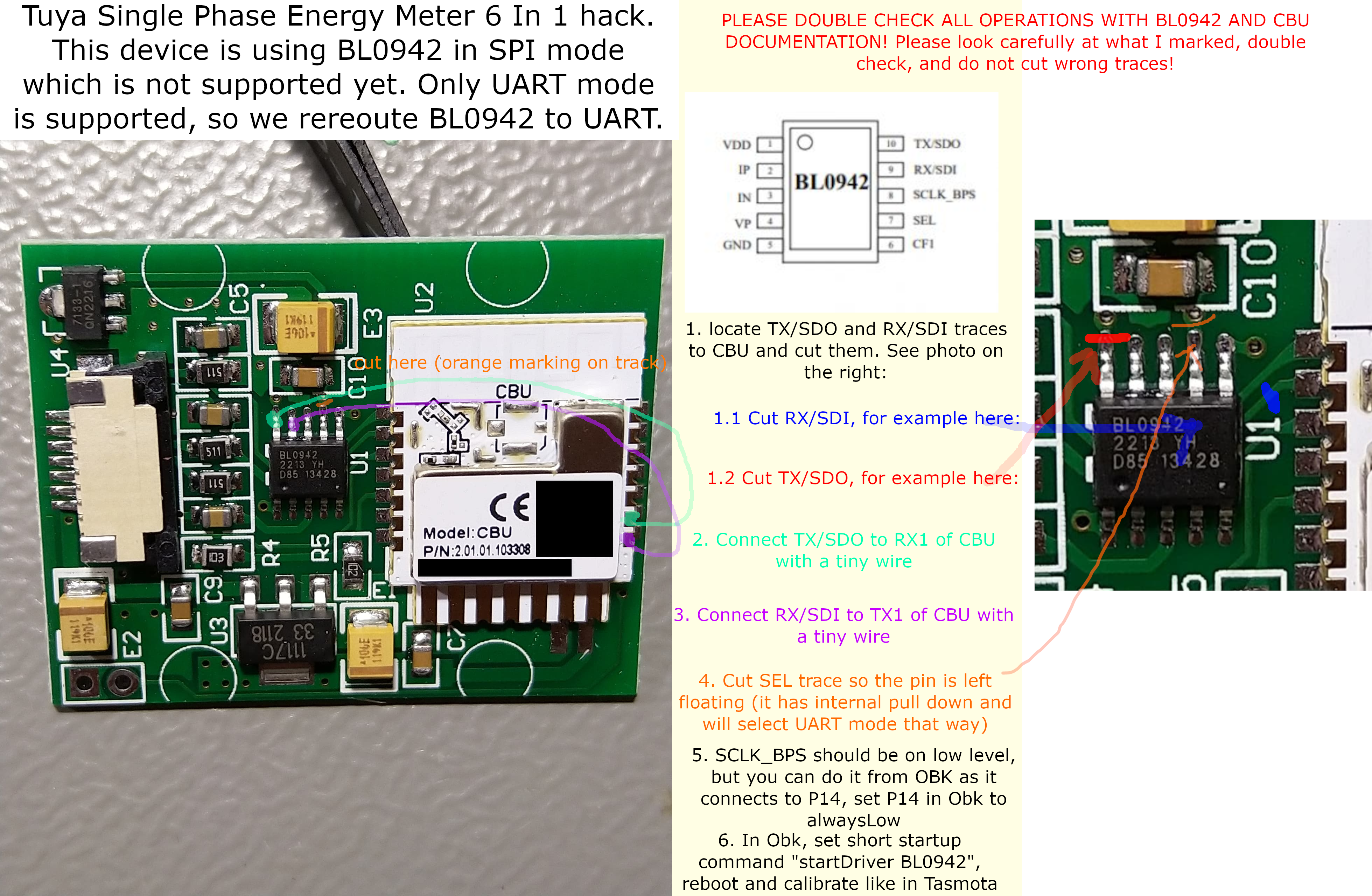
TODO: This device uses SPI, which is not yet supported. I'll update this post when it is working.
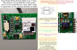
For the impatient, a hack has been proposed, which will convert the device to be connected by UART instead of SPI.
A modification like this can be made, and then load the existing bl0942 driver:


Comments
Thank you for detailed pinout, we already have one user who was looking for it. We don't have SPI support yet and I don't have this meter at hand. I could try to get SPI running with some other device... [Read more]
I can do the UART hack, but I'm not in a hurry, and I think the SPI working is a good goal for its own reason. You can see how much trouble the guy in the other thread had with his device :) ... better... [Read more]
Thanks, but first I need to do basic SPI support on my side. I can test it with any SPI device. I edited your post to remove part of IP. It will be useful in the future, but not now. BL0942 and TuyaMCU?... [Read more]
It's not sensitive, but thanks... that said, hiding 8 bits is like hiding no bits :P ... scanning 8 bit IP space is a few seconds effort. Best you take note of what it is and then redact it from the post... [Read more]
OK, IP redacted, I was in hurry. I am doing some post-new-year stuff but still keeping an eye on forum so I can help you and other users. Ok, to clear up things: - TuyaMCU is supported for a very... [Read more]
I wonder how accurate this measurement is, where only the N cable passes? https://obrazki.elektroda.pl/9264944300_1672653374_bigthumb.jpg [Read more]
Tuya device I mentioned is here: https://www.elektroda.com/rtvforum/viewtopic.php?p=20364819 The device in this thread is pending SPI implementation. Added after 2 [hours] 5 [minutes]: FYI,... [Read more]
Thanks, I will do that in a free moment. Are you going to attempt the UART modification? I am not able to do SPI support first. I will be looking into other requests first, like a software I2C. [Read more]
I don't need to do the UART mod. I'd rather reserve this as a test case for SPI whenever you get to it. My feeling is that devices in the support list should be minimally modified. The hack is fairly... [Read more]
Hi, thanks for the post and information. I'm trying to flash the module but it always fails with "Cannot get Bus." I tried many many times with different CEN to GND time but can't get it working. Did... [Read more]
I didn't connect the 5V, I flashed with 3.3V directly to the wifi module. I find I usually have more success when as little of the surrounding electronics are powered as possible. I did not use the CEN... [Read more]
Thanks for the quick reply. I tried it with directly 3.3V (CEN and power method), but still can't flash it. I double checked the TX/RX connection and never connected it the wrong way. The 3.3V LDO I... [Read more]
After some research the problem could be USB to Serial related. I read that the chip PL2303, which my USB to Serial is using, is no very stable/good. The best seems to be CP2102 followed by CH340G. Which... [Read more]
We are using that one: https://obrazki.elektroda.pl/9235746700_1676796304_thumb.jpg as you can see on our YT channel: https://www.youtube.com/@elektrodacom [Read more]
I ordered that one. It should arrive in two days. I borrowed a FT2232H Mini Module from work. Connected everything, double cheking TX to RX and vise versa as usual. Still no success. Not even with RTS... [Read more]
I got it to work. Thanks for your support! 1. My old serial adapter with 5V from USB to onboard LDO did not work 2. My old serial adapter with 3.3V from external LDO powered by 5V USB did not work 3.... [Read more]
Do you have C programming skills and would like to help us? [Read more]
I will try to contribute, but I don't know if I will have success :D [Read more]
Any help is welcome, you can also help with testing, docs, or with spreading the word (advertising) or... just donate so we can buy more devices for testing. Don't forget about our Youtube channel: ... [Read more]