Hello, I will present here the inside of the product known on the web as based on ESP8266, but in newer versions based on the BK7231T module, more precisely on WB2L. The lamp this time with a GU10 standard connector. It will also show here the procedure for changing its firmware. This time the programming pads from the WiFi module will be exposed, so you can change the batch without desoldering the entire module. Attention -
I suggest all readers to read the first topic in the series: LED WiFi RGBCW Tuya - interior, programming, BK7231N This topic will be a kind of extension of it, many procedures will be performed in an analogous way.
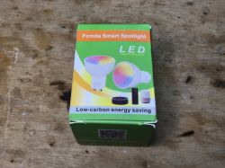
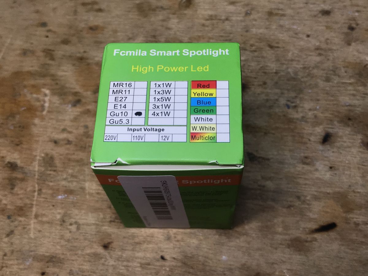
Purchase of the Fcmila smart spotlight These LED lamps, often incorrectly called "LED bulbs" by retailers, are quite popular on the web and are available in various online stores. It used to be built based on ESP8266, they even have a ready-made Tasmota template:
https://templates.blakadder.com/fcmila-spotlight-6w.html Unfortunately, over time, manufacturers switched to BK7231T, so for a long time it was impossible to program them.
Quote:
WARNING: New Tuya devices have replaced their Wi-Fi module with one incompatible with Tasmota!!!
Tuya-Convert might not be possible for this device since the template was added (2019-12-17).
That's why I create mine
OpenBeken (Tasmota-style firmware for other platforms) and I bought Fcmila GU10 to test it.
I do not know about you, but I do not use GU10 connectors for light bulbs at home.
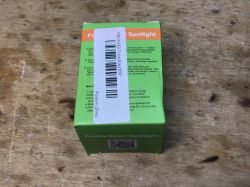
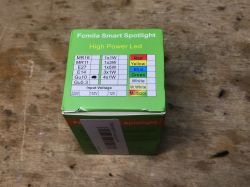
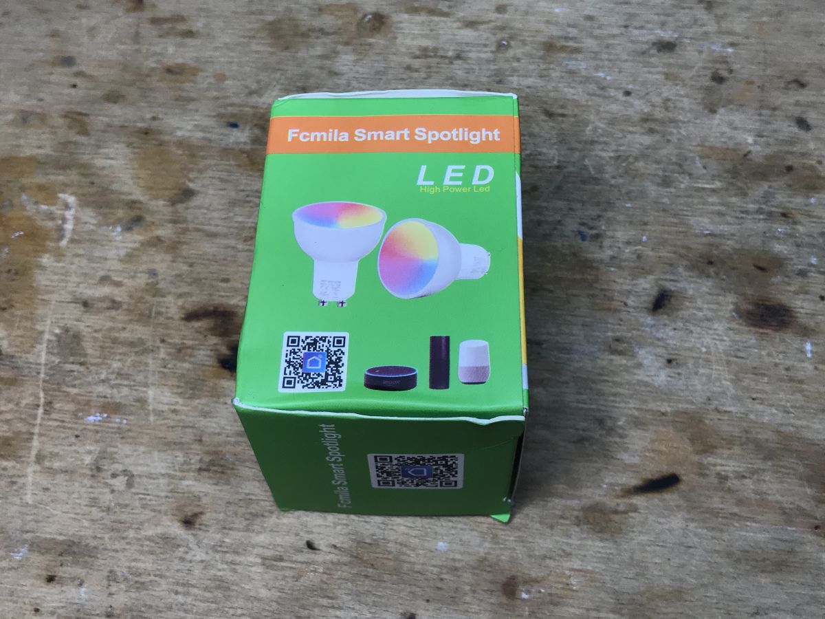
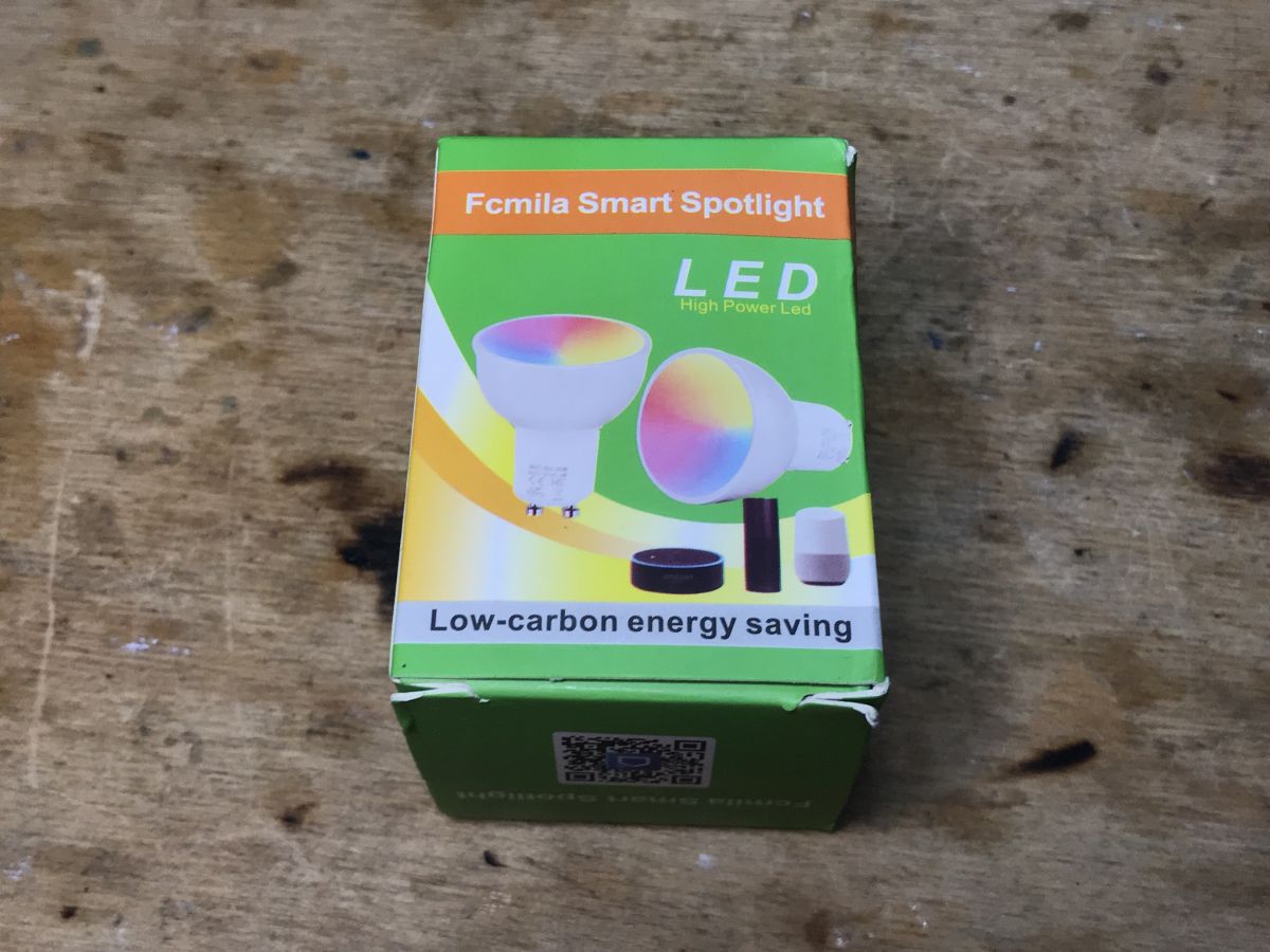
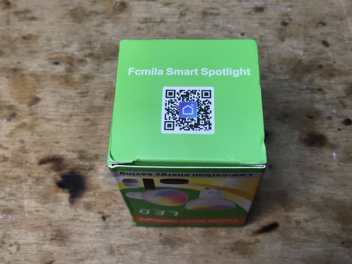
This is what the packaging looks like:
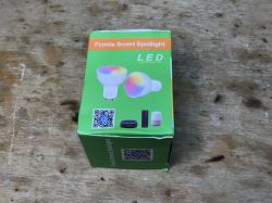
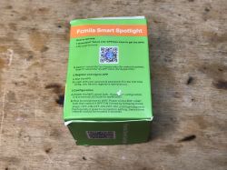

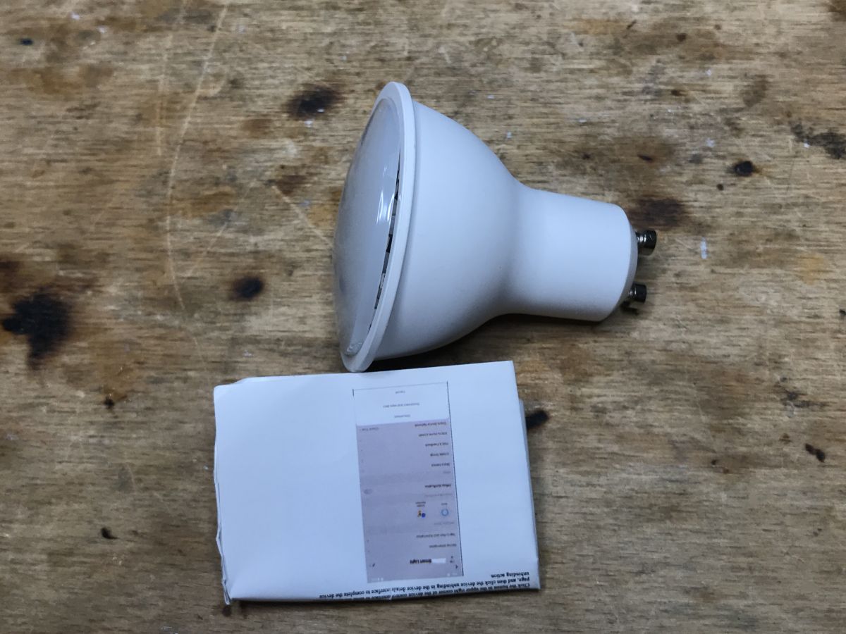
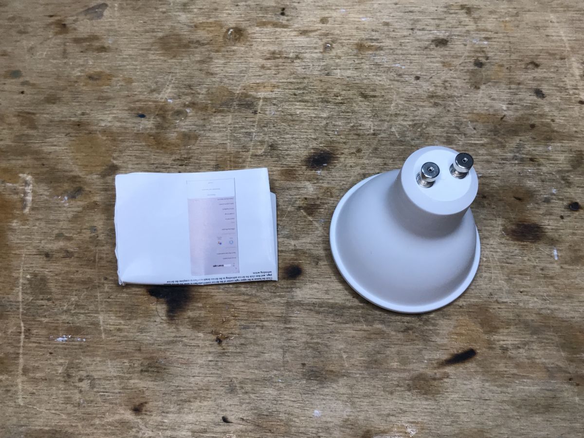
Kit Contents:
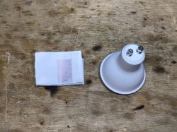
The product had a broken lid right out of the package. Didn't the manufacturer shut it down?
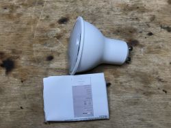
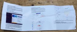
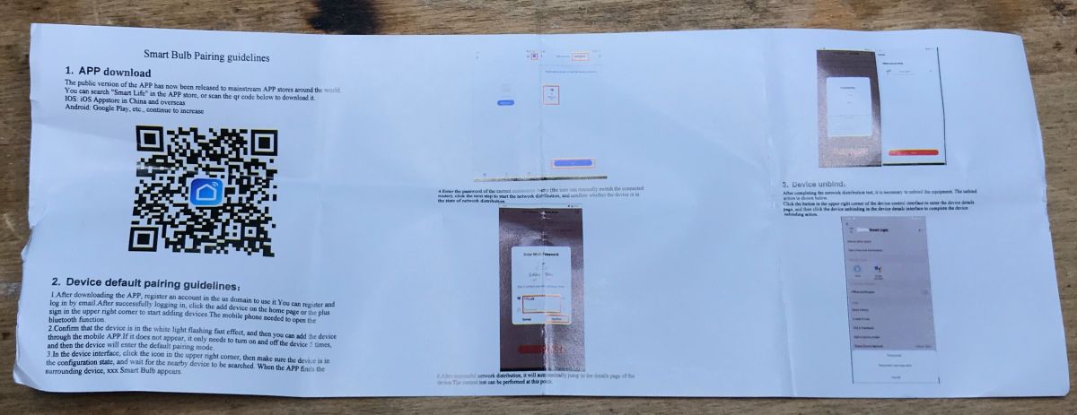
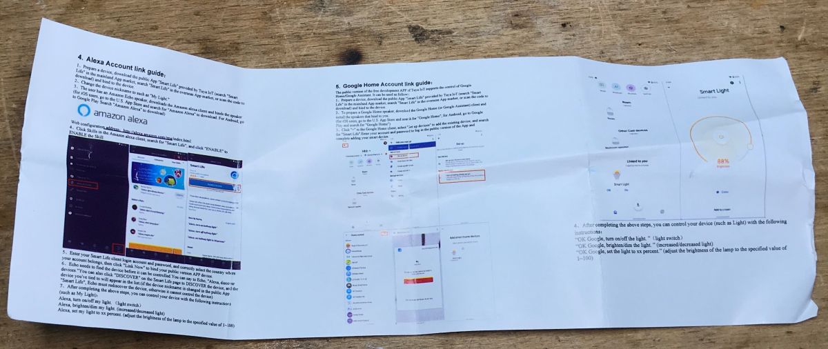
Instruction:

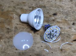
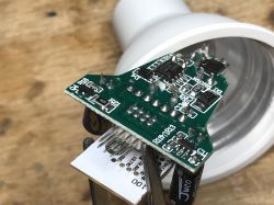
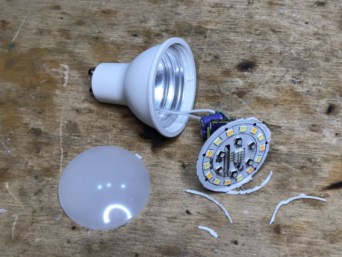
 Fcmil interior
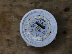
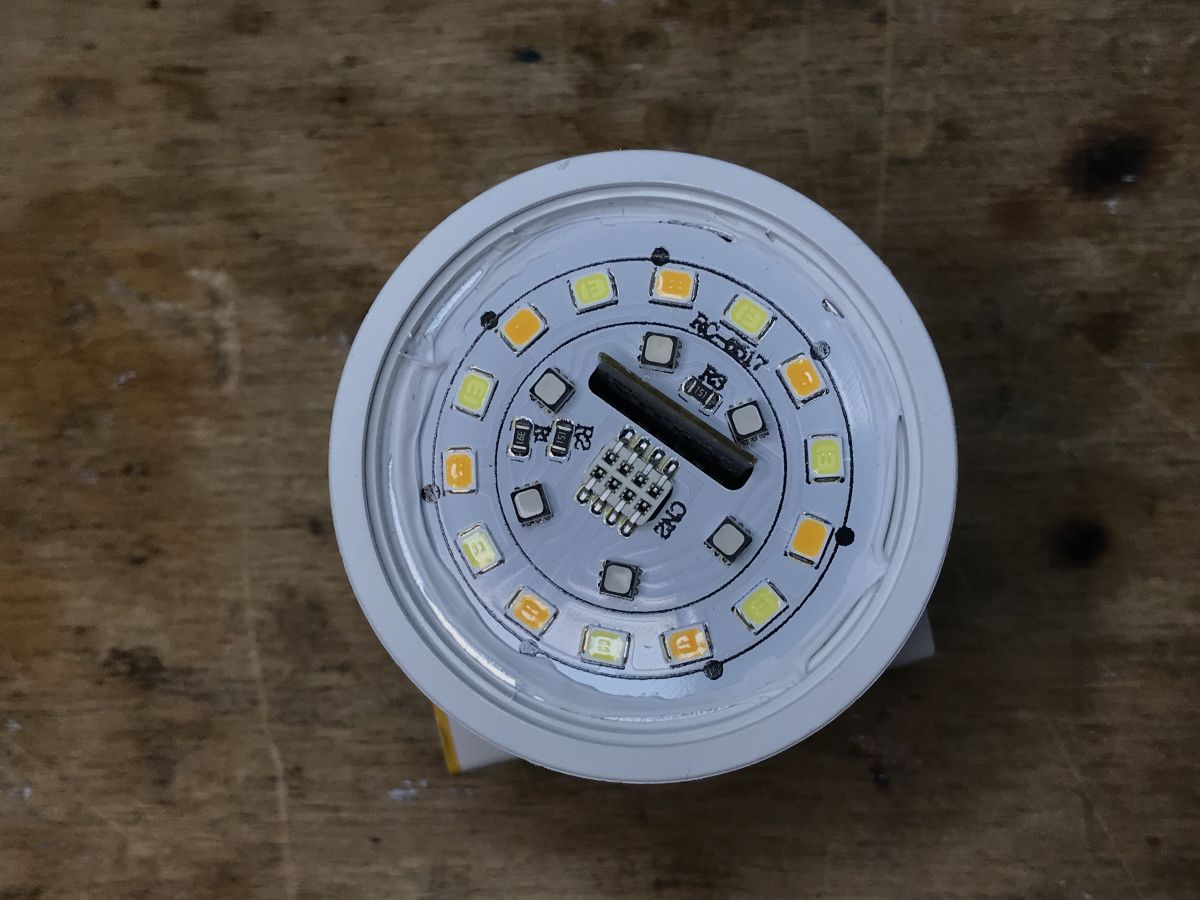
 The milky cover is enough to pry with a knife and we have access to the LEDs:
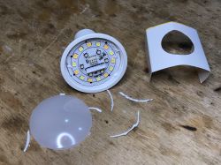
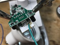
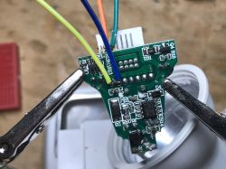
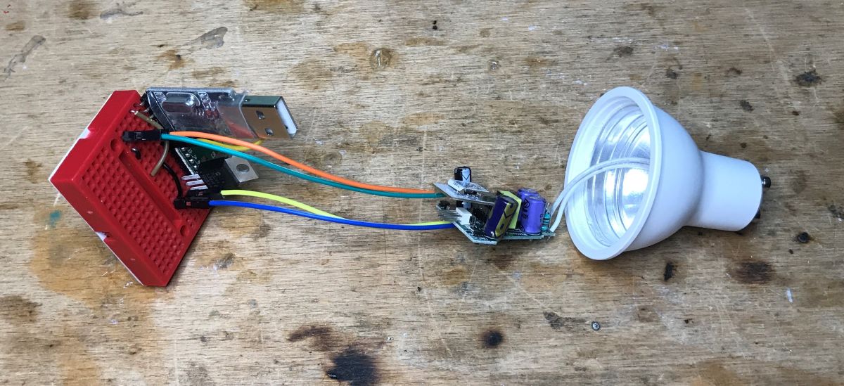
Electronics is on longer cables, it can be removed:

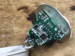
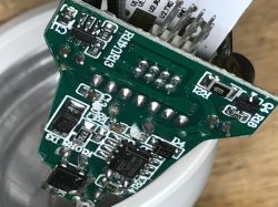
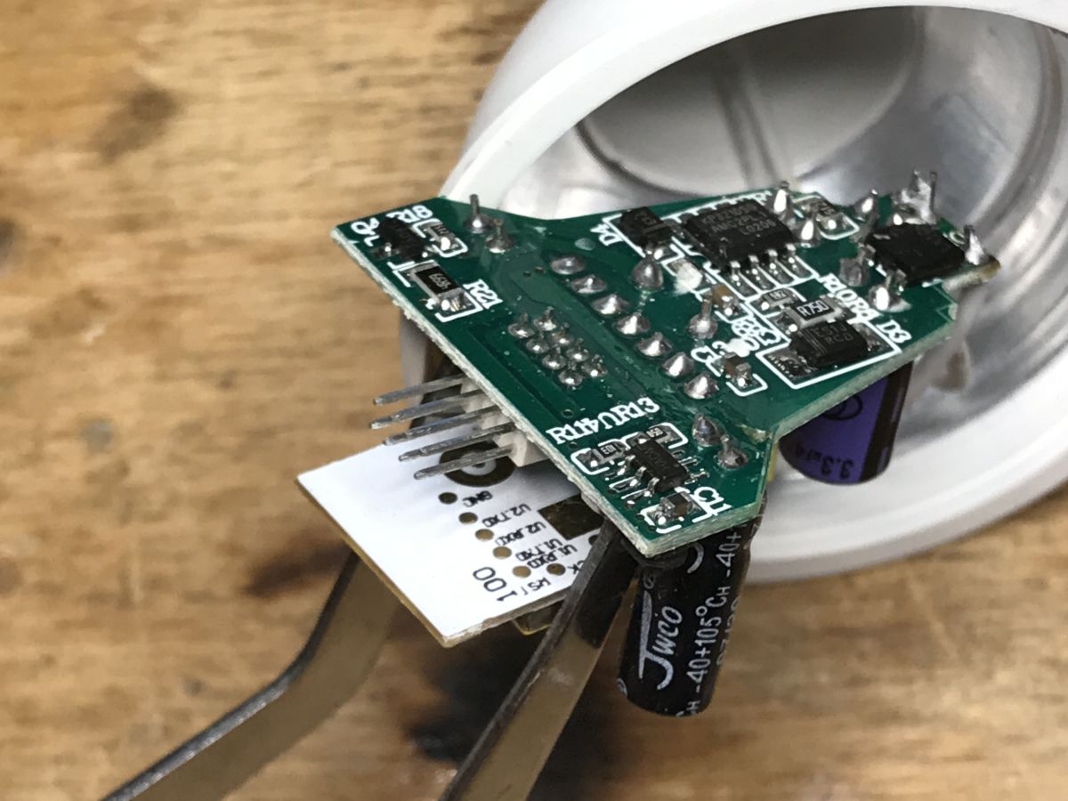
The input shows a fuse resistor, LX10N rectifier bridge and KP3210SG transformerless converter controller:

At the bottom there is also an SMD element marked HACAF - perhaps a 3.3V LDO regulator or a step down converter giving 3.3V?
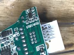
The R, G, B, C and W channels are controlled by separate transistors coded A09T (i.e. AO3400, N-channel MOSFET):
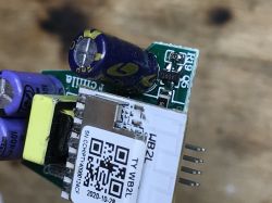
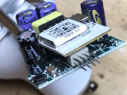
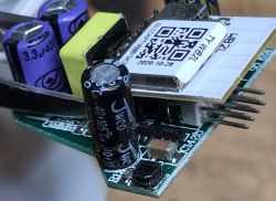
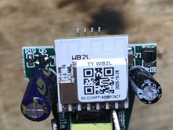
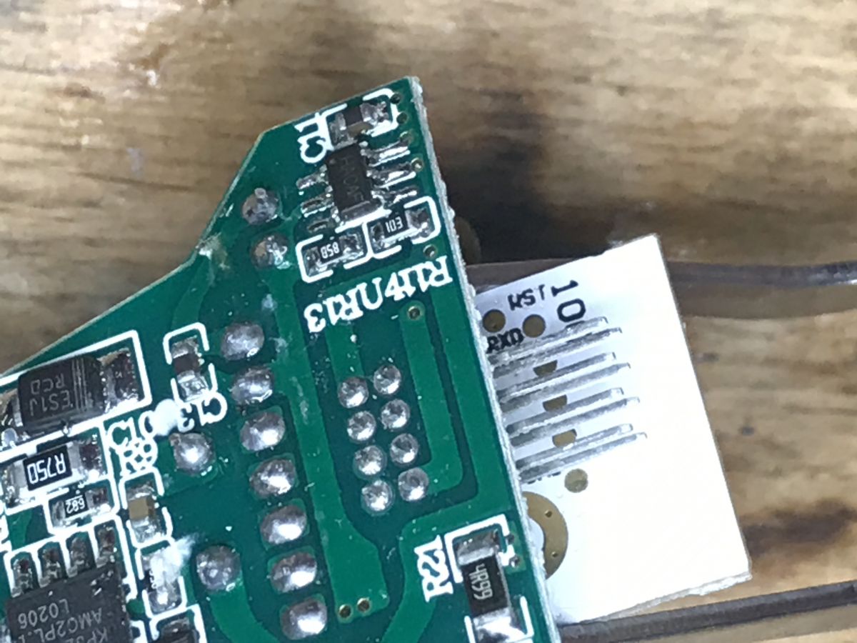
And of course there is the WiFI module with BK7231T - WB2L:
 Uploading the batch - bkWriter 1.60
 As in previous topics in the series, for example here:
Garden double relay Tuya CCWFIO232PK - BK7231T - programming This time, however, I did not use the method with the CEN/RST pin, I just rebooted the system by cutting off and reconnecting the power supply.
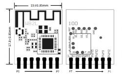
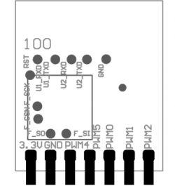
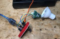
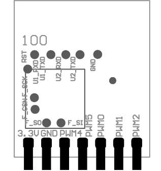
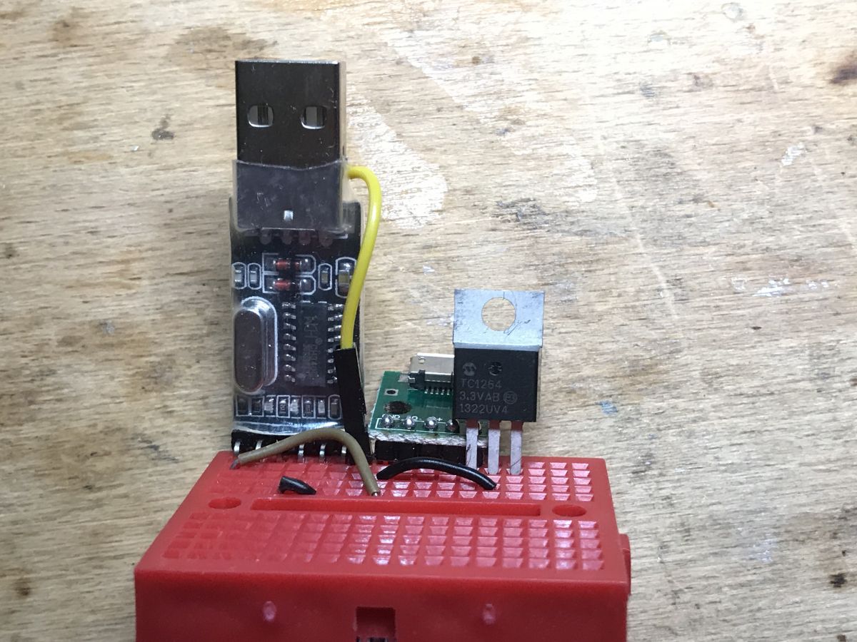
You need a USB to UART converter in 3.3V mode (the one based on CH340G is reliable) and four wires - 3.3V, ground, RX1 and TX1. Unfortunately, the signals from the UART are on the bottom of the WB2L, as in the pictures:
In addition - on the breadboard - a 3.3V LDO regulator (to get 3.3V from 5V), a USB to UART converter and a separate 5V connector for powering the LDO (disconnecting the power supply will be needed to reboot the system while the programmer is working, we cannot power LDO regulator from the same USB port in which the USB to UART converter is located, because too high starting current would reset the USB and stop programming at the very start):

 OpenBeken setup
 Everything as here:
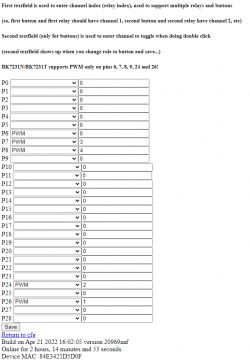
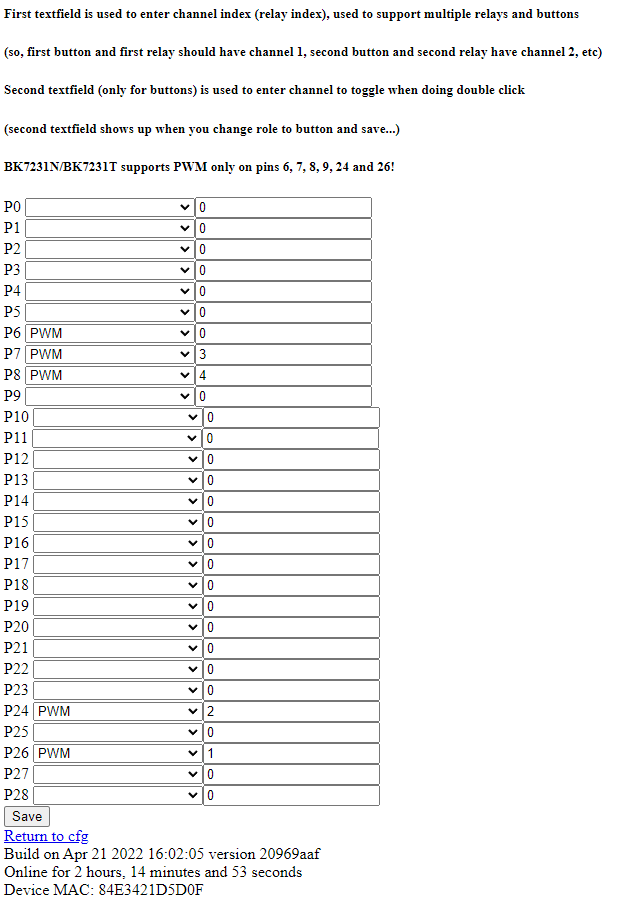
WiFi RGBCW Tuya LED lamp - interior, programming, BK7231N Pin configuration:
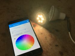
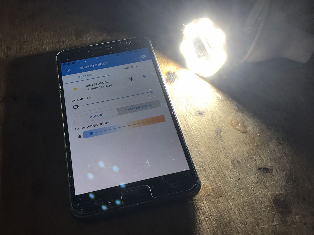
 Pairing with Home Assistant
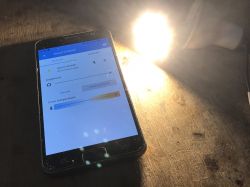
 It used to be paired manually:
WiFi RGBCW Tuya LED lamp - interior, programming, BK7231N But now we have Home Assistant Discovery support in OpenBeken:
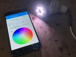
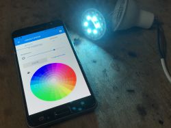
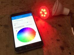
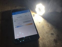
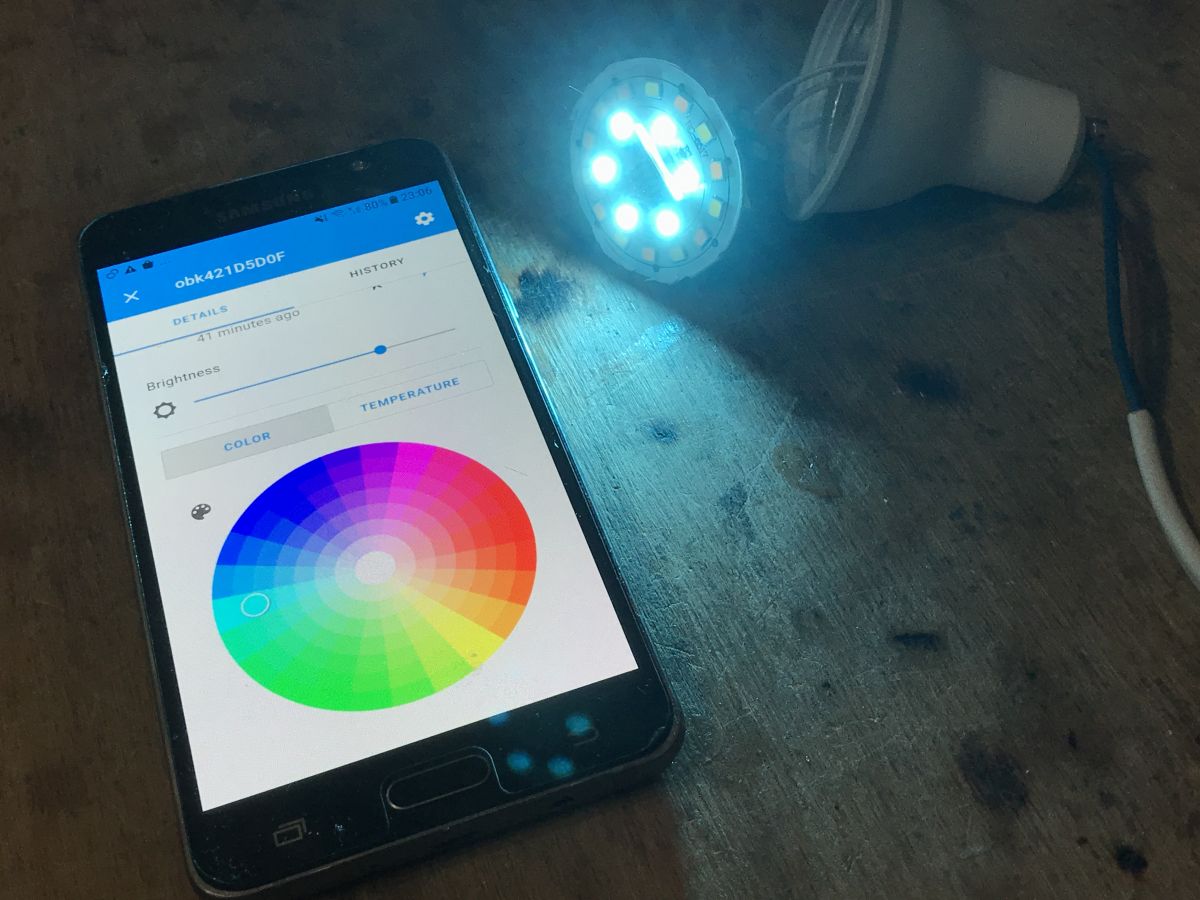
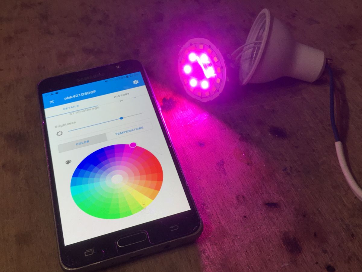
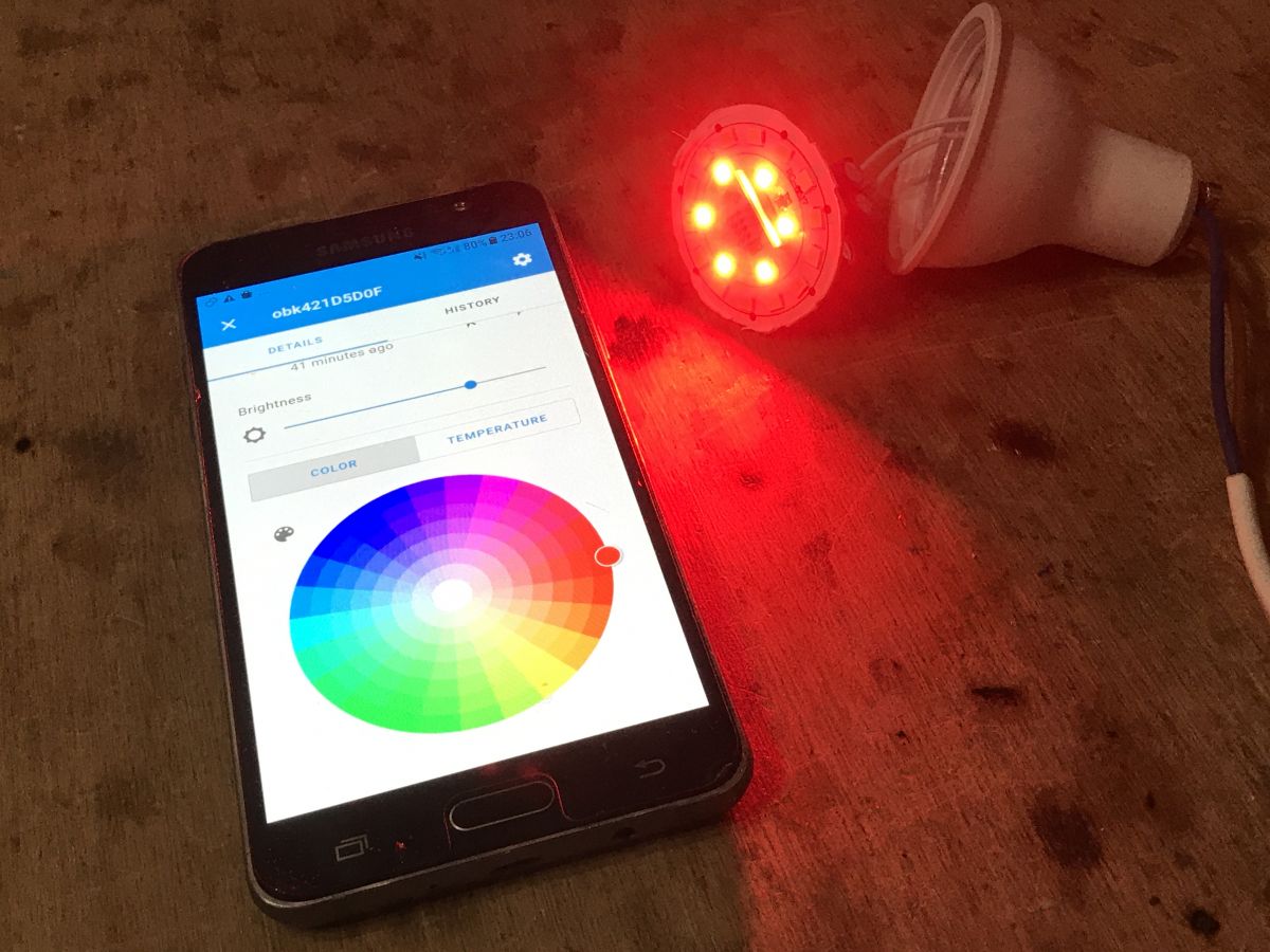
Effects:

 Add-on - OTA in OpenBeken
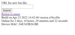
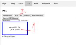
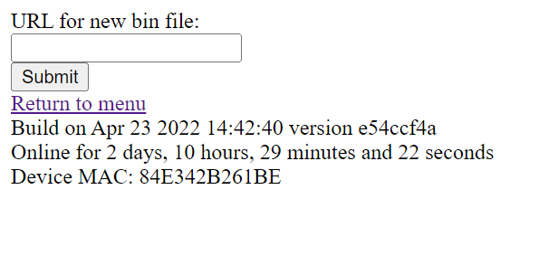
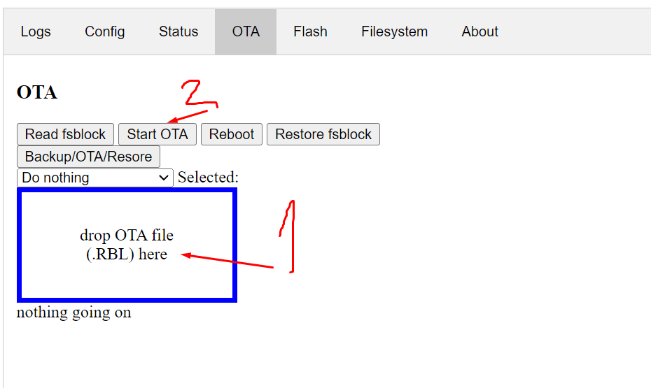
 OpenBeken supports OTA, i.e. batch update via WiFi. We must have OpenBeken already uploaded to our device beforehand. There are two OTA modes.
- mode via a link to the RBL file (for example from Github), i.e. in Config->OTA:
- mode by "drag and drop" the file (drag) to the field in the browser, it is in the Web App panel in the OTA tab:
 Add-on - Safe Mode in OpenBeken
 OpenBeken offers "safe mode"/reset to Access Point mode triggered by several times (2 times for access point mode, 3 times for mode without pin configuration) powering on and off the device. The work cycle of the device after starting must be shorter than several seconds. The device remembers how many full startups it has made and if there are several incomplete startups in a row, instead of connecting to our WIFI, it creates an open network, which allows you to save it and change its settings if we broke something.
Three times such a power-on/power-off cycle starts the device also without pin configuration and scripts (in case some of our script or setting, e.g. freezes the device, then it allows you to save it).
Appendix - commands and automations in OpenBeken To begin with, I must emphasize that OpenBeken is compatible with Home Assistant, so all scenarios with Home Assistant will also work for me.
What I will present here, however, is a way to automate without the participation of HA.
Basically, three ingredients are needed.
- an event system that allows you to execute commands when you press (or double-click or long-press) a button:
setEventHandler OnClick 11 [command here]
setEventHandler OnHold 11 [command here]
setEventHandler OnDblClick 11 [command here]
- channel control system (relays and PWM) through commands:
setChannel 1 0
addChannel 1 -10
- a system for sending commands to other devices, at the moment via GET:
SendGet http://192.168.0.112/cm?cmnd=Power0%20Toggle
This works somewhat similar to Tasmot HTTP. The authorization system will be added soon (although the general assumption is that the automation is rather sitting on a separate WiFi network).
Of course, sending the "Power0%20Toggle" command (by the way, %20 is just a space code in the HTTP request) is to send a second OpenBeken device to the light bulb, and more precisely a button. This is how you can pair a bulb with a button without an external server (even without HA).
Summary Programming this lamp turned out to be relatively simple. It's easy to get inside and put it back together. Programming pins from the WB2L module are available and you can solder the wires.
It is much better here than with other Tuya LEDs, which sometimes have the bottom of the WB2L module covered, so you have to unsolder it to get to the TX and RX.
If, on the other hand, you are wondering how to change the batch when the programming UART port is covered with a plate, then you will find the solution
on this video .
That's it for now. I can now control the lamp even via Tasmota Device Groups (OBK supports them), as well as via the DDP protocol, but more on that another time.


Comments