Which GPIO pins do I assign for the S06/S18 IR blaster?
Use P6 → Btn;1, P7 → IRRecv;0, P8 → LED;0 (or WifiLED;0 on WB3S), and P26 → IRSend;0 [Elektroda, zweigang, post #20467512]
Czy wolisz polską wersję strony elektroda?
Nie, dziękuję Przekieruj mnie tam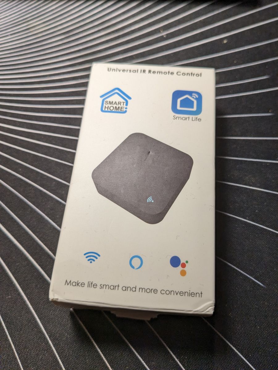


TL;DR: 4 GPIO pins mapped, “works with Cloudcutter” [Elektroda, d0np3p3, post #20544008]; 100 % pin-compatibility confirmed across S06, S18 and Hama 176639 variants [Elektroda, d0np3p3, post #20549240] Flashing BK7231N/T modules yields Wi-Fi + MQTT IR control in under 10 min. Why it matters: one cheap blaster can replace every legacy remote in your smart-home.
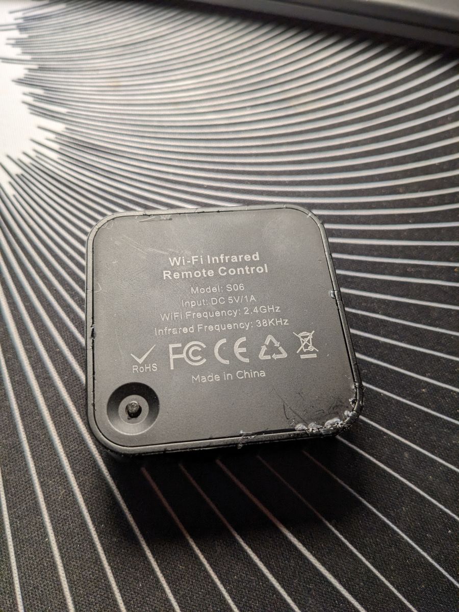
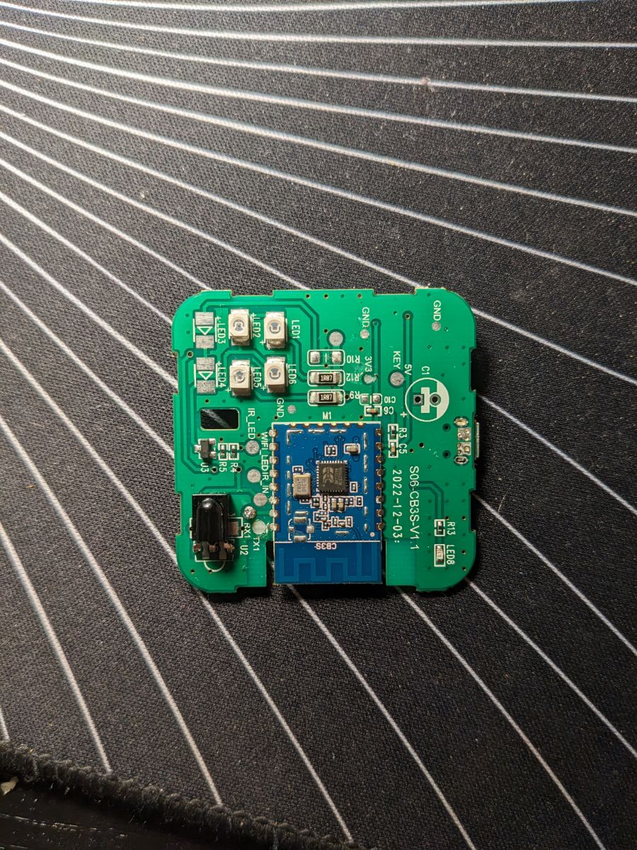
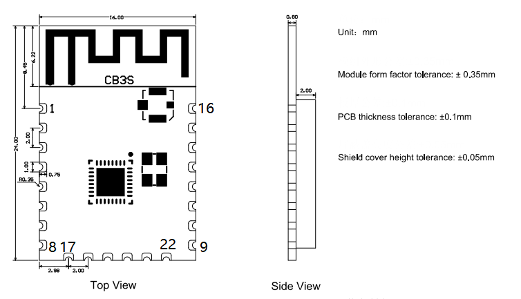
• Supply voltage: 3.3 V [Elektroda, zweigang, post #20467019] • IR LEDs fitted: 4 (with 2 spare footprints) [Elektroda, p.kaczmarek2, post #20467179] • Supported chips: BK7231N (CB3S) & BK7231T (WB3S) [Elektroda, morgan_flint, post #20765814] • Typical flash time: <3 min via USB-TTL [Elektroda, zweigang, post #20467019] • Reported range drop to 0.5 m after custom firmware [Elektroda, rakalexei, post #20560831]
cmnd/<DeviceName>/IRSEND with payload NEC-7A-1D-0 (example). A HA button card definition was shared by a user [Elektroda, campeanu, post #21209679]firmware_1.1.3.bin). Flash it via UART; remember to edit the MAC address bytes before upload [Elektroda, morgan_flint, post #20818497]CEN low (or simply cycle VCC with TX/RX connected) while powering up; the boot ROM enters serial mode, allowing re-flash without desoldering [Elektroda, zweigang, post #20467019]
Comments
That's a very interesting device, thanks. It should be very useful with OBK, especially that we will be soon updating IR support with extra library functions. There are, however, two things I can't... [Read more]
Hello, I think I used the word transmitter wrong. IR Blaster should fit better. Those 4 LEDs are the IR Leds to send the IR signals. I really dont know why there are two empty spots for additional LEDs.... [Read more]
Ah okay, I can see now. The 4 LEDs are IR transmitters and the status LED is the small LED on the other side other board (marked LED8). Now it's clear. Can you copy-paste JSON config from "Launch Web... [Read more]
Of course I will { "vendor": "Tuya", "bDetailed": "0", "name": "Full Device Name Here", "model":... [Read more]
Well, just copy-paste links from Elektroda to missing fields. I will add that device to online database later. [Read more]
On the webapp the template always resets itself but here is the template changed afterwards: { "vendor": "Tuya", "bDetailed": "0", "name":... [Read more]
The same configuration is working for S18 version of IR blaster: https://obrazki.elektroda.pl/5454636600_1680209358_thumb.jpg https://obrazki.elektroda.pl/9597187000_1680209358_thumb.jpg https://obrazki.elektroda.pl/2453695400_1680209359_thumb.jpg... [Read more]
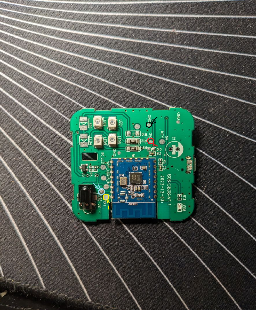
I just flashed my S06-CB3S-V1.1 via cloudcutter. I used the generic Tuya IR Device 2.0 CB3S I still have to confirm the PIN Settings for IR are working, https://obrazki.elektroda.pl/9305258500_1... [Read more]
Please post the device template from Web Application in JSON format once you have the GPIO roles setup and working. Thanks! [Read more]
I can confirm it uses the same Pins like in #1. Also this one uses the same: Link { "vendor": "Tuya", "bDetailed": "0", "name":... [Read more]
Hey guys, I have a question regarding how to read IR codes. I successfully flashed the device, filled out pins like this "pins": { "6": "Btn;1", "7": "IRRecv;0", "8": "LED;0", "26":... [Read more]
@rakalexei is the GPIO config correct? Take a look here, there should be logs in the Web App: A screenshot from the video above: https://obrazki.elektroda.pl/6201363100_1682071020_thumb.jp... [Read more]
@pkaczmarek2 Hey, thank you for your reply. I think I have some progress :) I changed my pins to this one "pins": { "8": "IRRecv;0", "24": "WifiLED;0", "26": "IRSend;0" } Now... [Read more]
It seems that IRSend command syntax is different. You can check this in our documentation. Search for the command name of your interest: https://github.com/openshwprojects/OpenBK7231T_App/blob/main/d... [Read more]
Here is the command - IRSend Samsung-0x707-0x7-3 Here is the result - Info:IR:Delay 110ms Info:IR:Delay 110ms Info:IR:Delay 110ms Info:IR:Delay 100ms Info:IR:IR send Samsung-0x707-0x7-3 protocol... [Read more]
The result looks correct. Maybe wrong IRSend pin. Otherwise, I would need to check myself on my Samsung to see if it works. We have an IR Library update in progress: https://github.com/openshwpro... [Read more]
@pkaczmarek2 Got it, thank you, probably yes, the pin is wrong, because the Receiver pin is different than in the first post of this thread, but the device looks the same. What is the easiest way... [Read more]
Maybe you can try the settings from here https://www.elektroda.com/rtvforum/topic3920360.html [Read more]
Tried different pins, but no result. Also used the phone camera to see IR LEDS - nothing, on other devices I can see LEDS through the camera. I'm stuck :) Not sure what else I can do... [Read more]