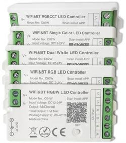
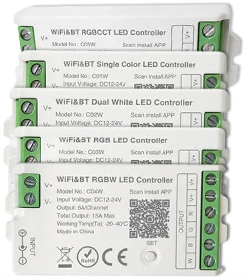
Here I will present the short teardown and OpenBK7231 programming procedure for a family of LED controllers.
They are based on CBU module, BK7231N
Unfortunately the CBU module is sandwiched between two boards, making access difficult.
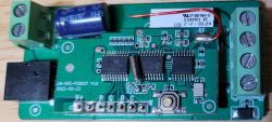
Here is the generic controller board, both sides:
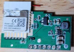
The generic controller has PWM outputs RGBCW to the mode-specific base board.
The PWM outputs are not attached to the CBU module!
The CBU module is connected via UART to a CMS32L051 microcontroller, which is also attached to the bluetooth radio and provides the PWM outputs buffered by a 74HC245.
I did not know how to get OpenBeken to connect to this CMS32L051 over uart, so the plan was to remove it and jumper to the CBU PWM pins:
To flash the CBU I desoldered the CMS32L051 which gave access to RX/TX on pins 5/6 (there is a series 1k resistor on both lines)
Connect:
CBU:16 RX or CMS32L051:6 - FTDI TTL-232R-3V3 Orange
CBU:15 TX or CMS32L051:5 - FTDI TTL-232R-3V3 Yellow
Flashing with the windows tool and a 3v3 FTDI cable was smooth.
Note: I had disconnected 1k resistors and connected directly on CBU pins.
I know with CMS32L051 installed, flashing is not possible.
I assume flashing will work through 1k resistors if CMS32L051 is removed, but this was not tested.
The RCBCW PWM lines are available on CMS32L051 pins 13/14/15/16/10
I have a C02W so I jumpered:
CMS32L051:10 to CBU:8 or P8, and configured this as Channel 5
CMS32L051:16 to CBU:9 or P7, and configured this as Channel 4
Doing this without desoldering the controller from the base board would be quite challenging but not impossible. I did split the boards apart as part of my investigation, but it was difficult to remove enough solder even with a desoldering gun.
For some reason OpenBeken would not set the outputs (i.e. Channel 0 = 0.00, Channel 1 = 0.00, Channel 2 = 0.00, Channel 4 = 0.00, Channel 5 = 0.00) if I only configured channels 4 and 5.
So I also configured P6 as channel 1 and P9 as channel 2 which makes this a RGBCW device, and now channels 4/5 work, with channels 1/2 not connected to anything and channel 3 not configured.
I now have a C02W working with OpenBeken.
There is very likely a better technique, but this was my first OpenBeken device. Any advice would be welcome - I want several such modules but I'm not sure it's worth the hassle.


Comments
Hello, there are several ways to improve the workflow here. 1. you can do a 2MB flash backup of this device and use it then to flash next pieces without soldering wires 2. removing MCU and using PWMs... [Read more]
Thanks for the suggestions! I did take a backup of the original firmware if it is of use to anyone, let me know. I'm not sure what you mean about 'flash without flashing'. That's great there is... [Read more]
Sorry, it seems that part of my message was lost during edit. I meant that doing 2MB backup allows you to flash without soldering wires, remotely, via the cloudcutter program. That way you can upload OpenBeken... [Read more]
Hi, I got another device and recorded the UART as requested. 9600 baud 8N1 on pin 5 Unfortunately the device isn't recognized as Cool/Warm, it appears as just a single channel "Smart Wi-Fi Dimmer"... [Read more]
Here is the tool used: https://www.elektroda.com/rtvforum/viewtopic.php?p=20528459#20528459 Here is interpretation: https://obrazki.elektroda.pl/7167227900_1682111552_thumb.jpg The packet above... [Read more]
Thanks for your help. I've been at it for a few hours, not figured out yet. I have only one kind, cool/warm. The app detects it as monochromatic. I can't seem to manually add a C/W version either, it... [Read more]
Hi Everyone, I also got this device today, the CW01 version. Flashing with cloudcutter worked flawlessly, however the config seems a bit more demanding. - With the Tuya App the device worked as expected,... [Read more]
Hi jrhenk, You might have missed the part where I desoldered the TuyaMCU and directly soldered wires to the CBU. I don't recommend you follow this procedure though, since it's a pain. Thanks to... [Read more]
Thanks for the quick reply! I saw that but also the follow up that it's not necessary if you load the tuya driver, made me not getting my solder iron out :) I also saw the info about the dpIDs yet I'm... [Read more]
Hello, good job, assuming that this is true: You can use approach from this topics: Dimmer EDM-01AA-EU 300W for BK7231 and TuyaMCU - configuration MoesHouse DIY Smart WiFi Light LED Dimmer Switch... [Read more]
Oh yes, it's completely working now, thanks so much for the config!!! Thanks to it, I also have a better chance now to translate the initial findings into a config syntax since I had now idea how to do... [Read more]
What does the log say during boot? Connect UART to USB converter RX to TX2 pin of your module. [Read more]
Is there any way to do this remotely? Already installed it into a ceiling and also a bit afraid I break it after all with my still beginner's soldering skills edit: interesting, after configuring mqtt... [Read more]
open web app log, press reboot, clear log, and wait for the log to update, it will show a great chunk of things that happen at startup [Read more]
Ah ok! I thought you'll see even more when connecting cables, here's what it shows: Info:MAIN:Module reboot in 1... 001/2/set Info:MQTT:MQTT client in mqtt_incoming_data_cb data is 0 for ch 1 Info:GEN:No... [Read more]
alright, with the newest firmware and the wifi quickconnect flag set I won a couple of more seconds, and it's now down to 20 which is pretty much the same that I also get with a couple of other devices,... [Read more]
The issue is closed. I can't think how it can be any faster. Here's a sample from my WB3S LED strip, I need 7 seconds to get to NTP ready: Info:MAIN:Main_Init_Before_Delay Info:CFG:#######... [Read more]
Thanks for the reply and it wasn't so much about the NTP I was just jealous about the quicker bootup time :) In the meantime I think I actually found a fix!! For some reason if you start using the Wifi... [Read more]
I didn't know about that "full power off and power on" requirement. This is new to me. Maybe it didn't occur with my devices. @dedamraz have you noticed anything like that? I will try to add that full... [Read more]