FAQ
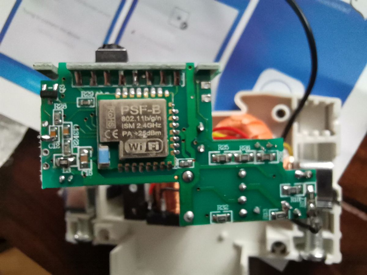
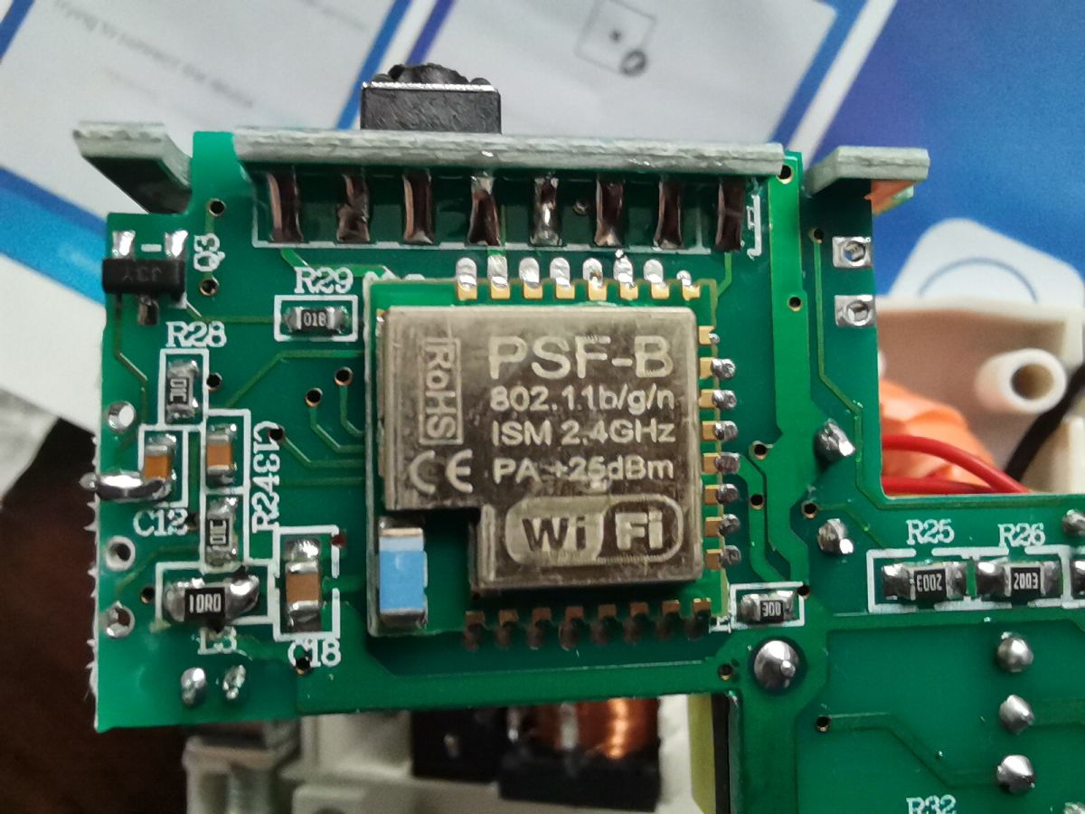
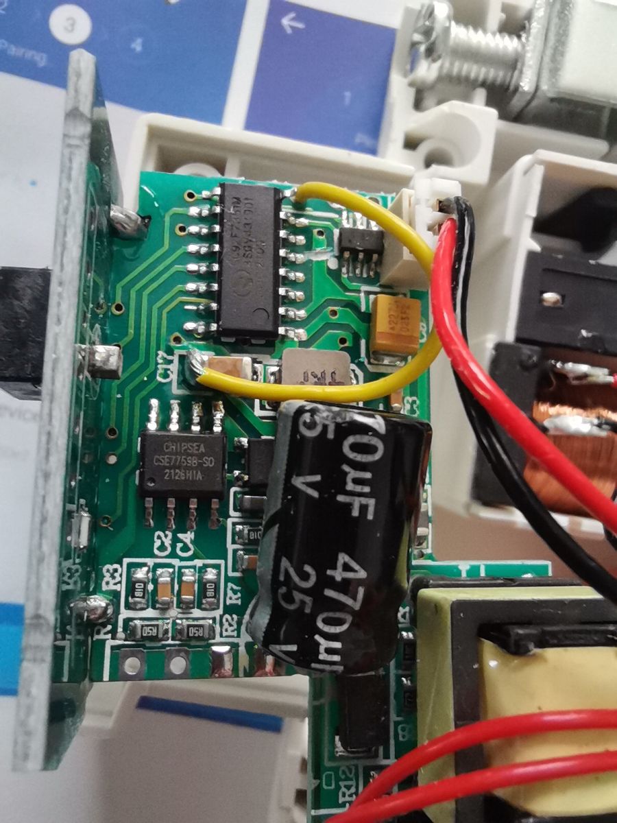
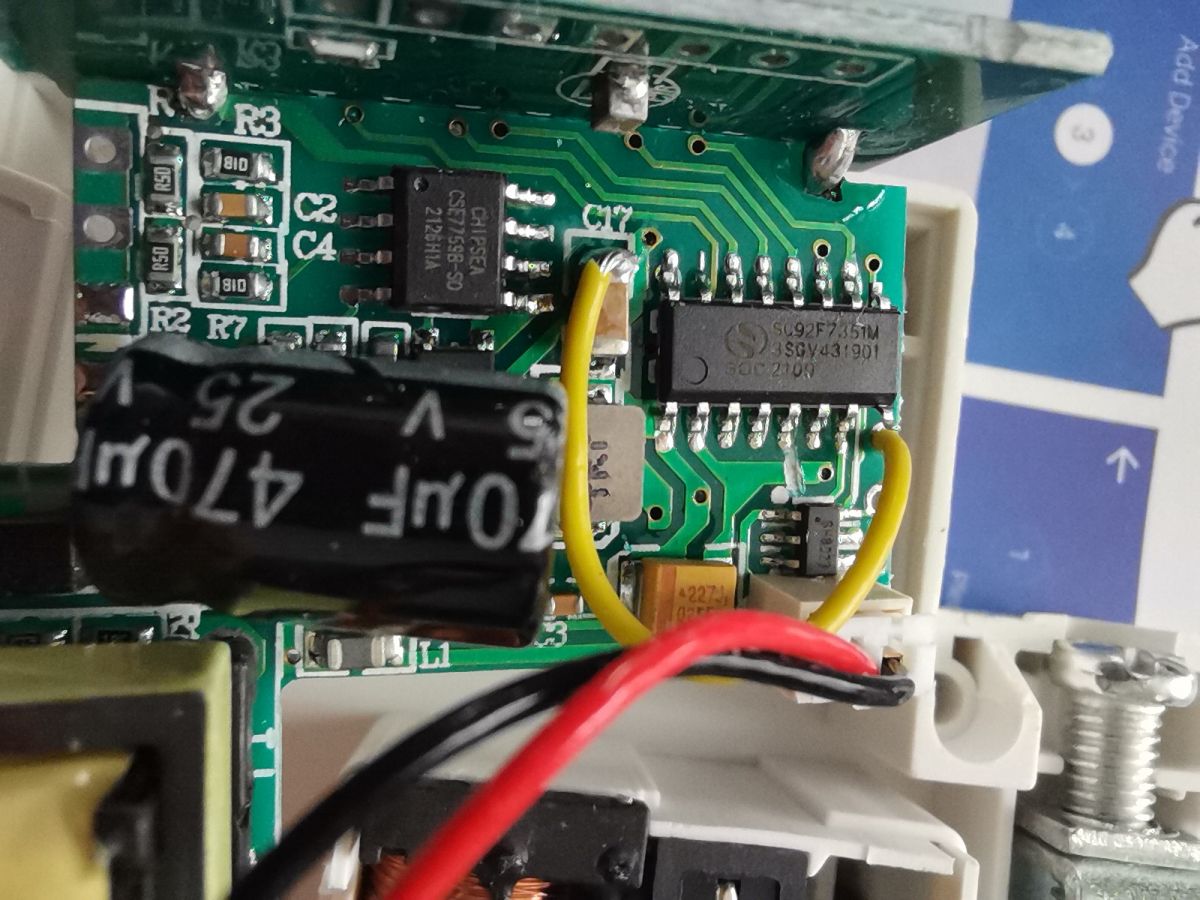
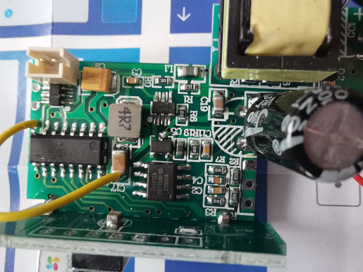
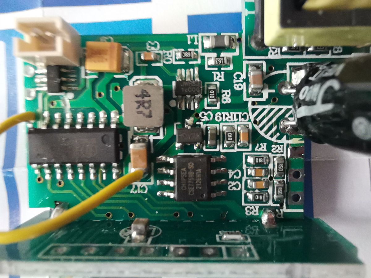
TL;DR: A 19 mm-wide WiFi DIN breaker combines an ESP8285, SC92F7351 MCU and a 300 mA relay driver—“a very interesting teardown” [Elektroda, p.kaczmarek2, post #20529044] Open-source firmware works once the CSE7759B line to RX is cut [Elektroda, civic9, post #21158268] Why it matters: You get compact power metering, remote switching and Tasmota freedom in one rail-mounted unit.
Quick Facts
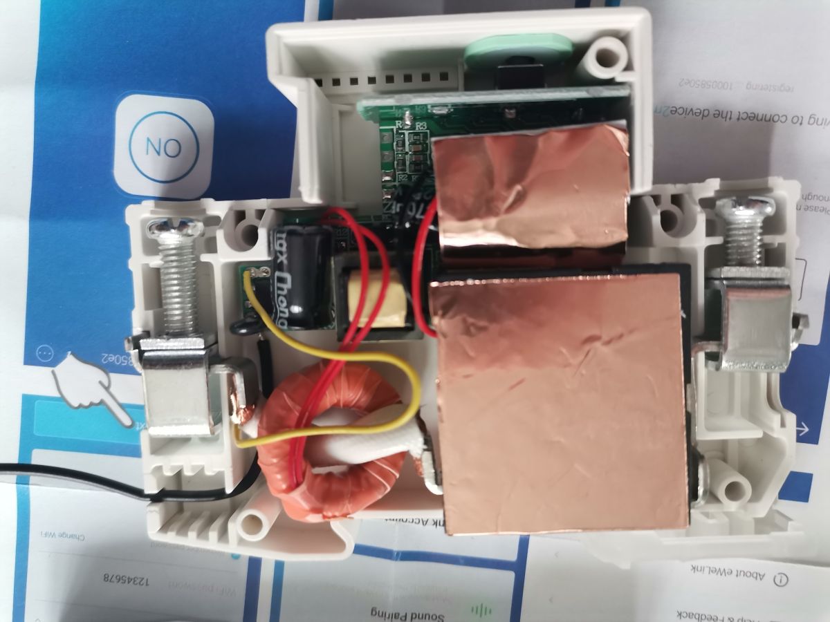
• Width: 19 mm 1-gang DIN enclosure [Elektroda, ststefanov, post #20528974]
• Core WiFi SoC: ESP8285, 1 MiB embedded flash [Espressif, 2022]
• Relay driver: BL8023F, 300 mA bi-directional output [BL8023F Datasheet]
• Energy-meter IC: CSE7759B, ±0.5 % accuracy typical [CSE7759 Datasheet]
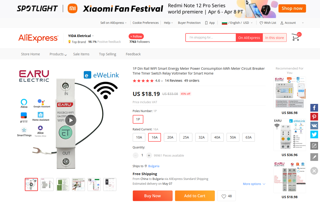
• Street price: ≈ US$14 per piece on AliExpress [AliExpress Listing, 2023]
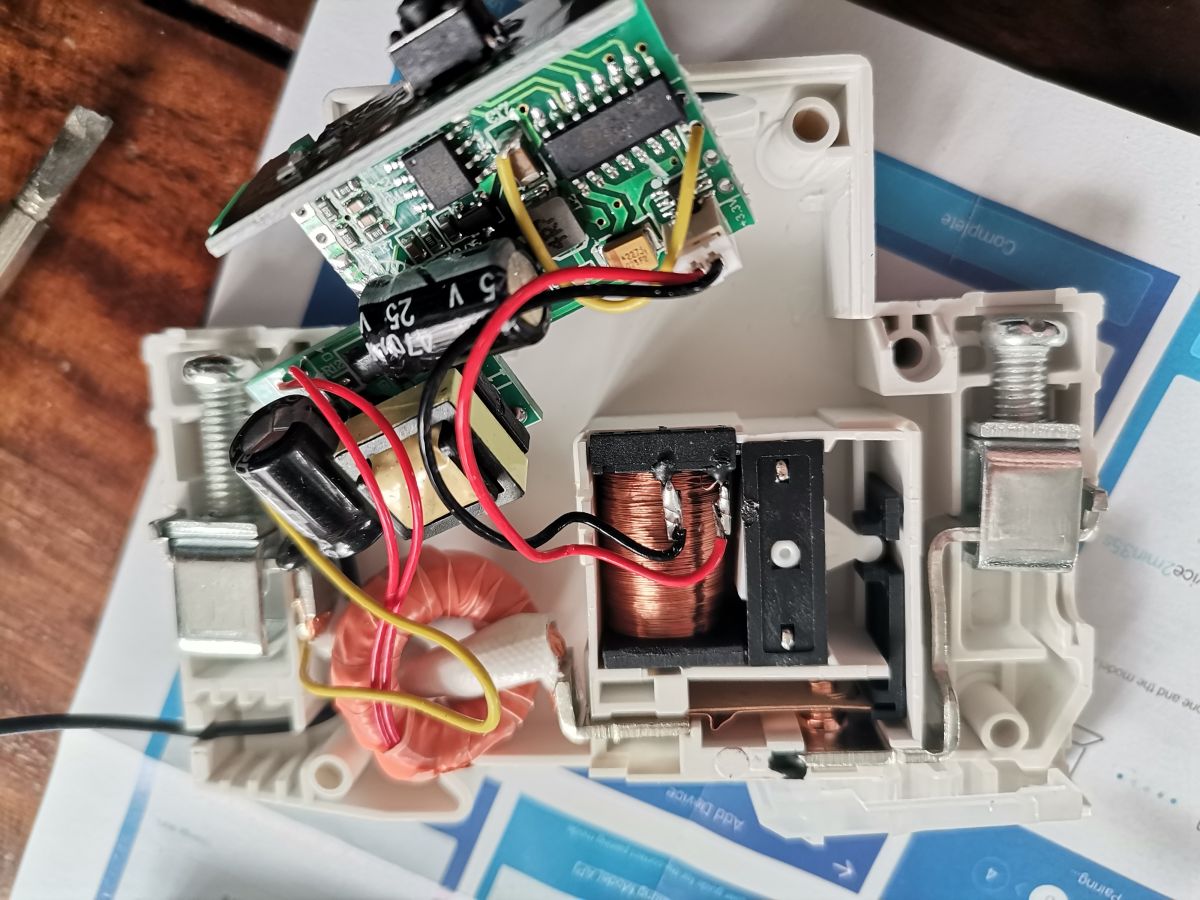
What chips are inside this DIN-mount breaker?
Why did the designer add the SC92F7351 when the ESP8285 is powerful enough?
The SC92F7351 isolates critical protection logic from WiFi tasks; if the ESP crashes, the 8-bit MCU can still open the relay, improving safety, a common dual-CPU strategy in protection gear
[Elektroda, ststefanov, post #20528974]
Is the module a TuyaMCU device?
Despite a Tuya-style PSF-B PCB, UART sniffing shows no TuyaMCU packets; ESP GPIO12 drives the relay directly, so standard Tasmota GPIO mapping works
[Elektroda, civic9, post #21158268]
Can I flash Tasmota without desoldering the ESP?
3-step how-to: flash Tasmota on the PSF-B module
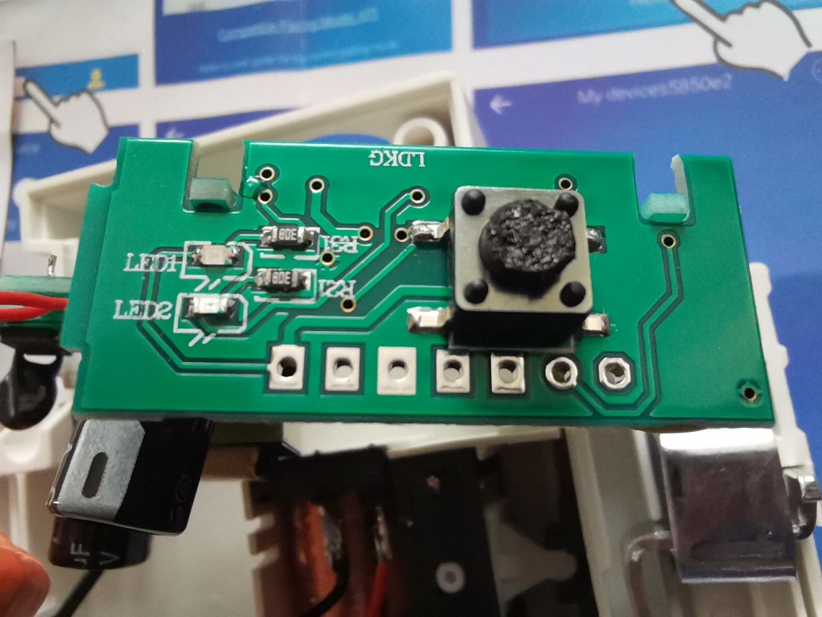
- Drill the plastic rivets and open the case (non-reversible). 2. Cut or lift the CSE7759B-to-RX line, pull GPIO0 low, and power the board at 3.3 V. 3. Use the web Tasmota installer or esptool to write tasmota.bin, then remap GPIOs (0-Button, 3-CSE7766 Rx, 12-Relay, 13-LED) [Elektroda, civic9, post #21158268][Elektroda, p.kaczmarek2, post #21177522]
What GPIO configuration works in Tasmota?
Which SOT-23-6 part sits beside the relay socket?
What happens if the BL8023F fails?
A shorted BL8023F can latch the relay closed, defeating trip functionality; an open-circuit failure leaves the load permanently off. Replace the IC or bypass with a new driver after verifying coil resistance [BL8023F Datasheet].
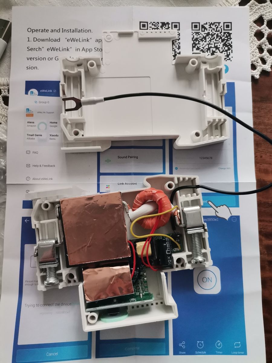
Was opening the enclosure destructive?
Yes. Two plastic rivets hold the halves. Drilling removes them but you can later fit small M2 screws, restoring integrity without re-riveting
[Elektroda, civic9, post #21203305]
Can I reuse a GPIO to run RS-485/Modbus inside the panel?
You can, but add an isolated RS-485 transceiver (e.g., MAX3485 + DC-DC) to protect the ESP. Direct wiring risks ground loops and exceeds 3.3 V tolerance [Maxim, 2023].
What pinout does the PSF-B module expose?
How accurate is power metering after Tasmota flash?
With factory calibration intact, users report ±1 % power and ±0.01 kWh counter deviation over 24 h, close to the CSE7759B’s ±0.5 % spec
[Elektroda, civic9, post #21202375][CSE7759 Datasheet].
Any size or thermal limits to consider?
The 19 mm body fits one pole but limits heat sinking; continuous current above 16 A raises internal temperature by ~25 °C, so derate for ambient >40 °C [Manufacturer Sheet, 2023].
Comments
Thank you, that's a very interesting teardown. I haven't been aware about the PSF-B module, but luckily pinout is already known: https://obrazki.elektroda.pl/6716991900_1680862747_thumb.jpg Right... [Read more]
hello, anybody can identify transistors matrix in sot23-6 package, near relay socket, after some tests i have dead this transistor. thanks in advance Gintas [Read more]
The chip is BL8023F 300mA Bi-Direction Relay Driver https://obrazki.elektroda.pl/7249207200_1681305916_thumb.jpg [Read more]
Thank you, my friend. [Read more]
Hi, Can I flash it with Tasmota or other open-source software? Do I need to disable that TuyaMCU to flash PSF-B? How? Does anyone have a working configuration? Please give me any tips and hints about... [Read more]
Yes, Tasmota is a good choice for ESP-based devices. You can also use online Tasmota installer, as described here: https://www.elektroda.com/rtvforum/topic3990951.html [Read more]
What are the counter values displayed in Tasmota? Could you post some screenshots/logs please? [Read more]
https://obrazki.elektroda.pl/8394507100_1724516774_thumb.jpg [Read more]
Thanks. I am also interested in the device because of the form factor. Was the opening of the device destructive? [Read more]
I've did a more detailed teardown of a similiar (same factor) device once, also on ESP, but you will need to use google translate: Przekaźnik Tuya/Smart który pamięta harmonogram po utracie sieci Wi... [Read more]
Found this youtube video: https://www.youtube.com/watch?v=jrmQpzMRU6o Added after 19 [minutes]: Thanks. Actually what I need is a ESP device in the switchboard to connect to few ModBus... [Read more]
Rivets are used to hold two parts of an enclosure together. So dissasembling it is somewhat destructive. However, rivets can be drilled out quite easily and you can replace them with small screws afterward. ... [Read more]