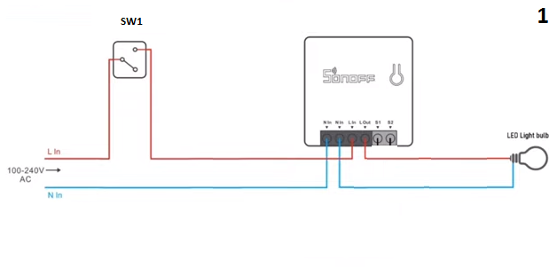
This universal assembly adapts a Sonoff smart relay for AC devices with SW1 manual control and remote control only when SW1 is closed.
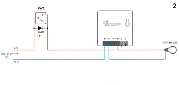
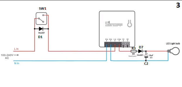
D1 keeps Sonoff online when SW1 is open, and R3, D7, and C2 reduce flicker by feeding the bulb from a DC-like discharge path.
C2 charges through D7 during the 10 millisecond AC negative half cycle; Sonoff relays usually tolerate 10 or 16A.
T1 closes S1-S2 when SW1 closes, so the bulb can be switched on and off through Sonoff after the trigger logic is configured.
The circuit is not suitable for loads that truly rely on AC internals, such as a ceiling fan, though some DC fans may work.
AI summary based on the discussion. May contain errors.
This assembly is universal. Suitable for all types of AC devices.
You can control the device manually through SW1 but remotely only when SW1 Closed.
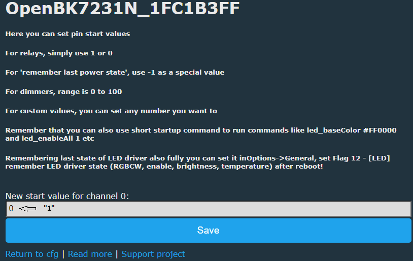
And you need to configure Startup like this:
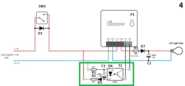
When SW1 opened, Sonoff Offline. In order for Sonoff to stay in line with SW1 Open, we added D1.
Now with SW1 closed the bulb turns on normally, but when SW1 is open the bulb flashes. To correct that we add this:
R3 limits the current through D7 when C2 is discharged when the device is connected to the AC mains. C2 charges through D7 during the AC positive half cycle and begins to discharge through the bulb during the 10 millisecond AC negative half cycle. The bulb is running on DC despite being an AC device (explained later).
We already eliminated the flicker but when opening or closing SW1 the bulb stays on. We need a trigger:
But for it to work we need to configure this:
Now we can turn the bulb on and off by controlling Sonoff via S1-S2. When SW1 closed, T1 conducts and closes S1-S2. When SW1 open, T1 does not conduct and opens S1-S2.
Why are Sonoff and bulb working if they are AC devices?
Because they work internally at DC. That's why we can't connect a device that works internally with AC like a ceiling fan, for example. But there are DC fans, I think these could work with this assembly for the same reason that Sonoff and led bulb do.
AC devices work with assembly 1, which is universal, as long as the current consumed is less than what Sonoff's internal relay can withstand (usually 10 or 16A).
Something like this from Chinese sellers:
https://pl.aliexpress.com/item/1005003337087512.html?spm=a2g0o.cart.0.0.24f8452cnVM6zT&mp=1&gatewayAdapt=glo2pol
I bought 2 of them myself and they work gre... [Read more]
spin55
18 Apr 2023 10:03
Thanks for the link. I did not know that. [Read more]
ferbulous
19 Apr 2023 08:43
@kaczmarj
I’ve bought it before as well, what’s great is you can flash tasmota/esphome since ewelink diy mode works and it’s small enough to fit behind the switch.
Not ideal for 2 way switches unless... [Read more]
spin55
19 Apr 2023 11:47
We already knew it worked.
If it works with one wall switch, it works with two or three.
Enjoy it!!
This:
https://obrazki.elektroda.pl/2043322700_1681897545_thumb.jpg
And this is the same:
... [Read more]
ferbulous
19 Apr 2023 11:55
@spin55 my wife just called and complained the ac’s 20a switch is not turning on and asked me to check on it.
Oddly enough this happened after i did the modification for the 2 way switches and both (light... [Read more]
spin55
19 Apr 2023 14:54
I think the same as you, that they are different circuits, but you never know.
There is only one way to clear up doubts: disconnect the assembly and see what happens. [Read more]
ferbulous
21 Apr 2023 10:35
@spin55 looks like it’s not related
Gonna need to call someone to check it since replacing 20a switch doesn’t fix it
By the way i have a 5 Gang switch, could i just use 1 diode and loop from live to... [Read more]
spin55
21 Apr 2023 12:23
I don't understand what you want to do. If you do a freehand sketch I could try to give you a coherent answer. [Read more]
dead2112
28 Jun 2023 03:32
Hello, is there any difference between using a single capacitor? Also, does the capacitance matter? Some have a 0.4 uF and anothers user 2 uF or 4.4 uF.
I have seen some devices that includes only a single... [Read more]
spin55
28 Jun 2023 18:25
Hello. If you really want to understand why capacitors are used instead of resistors in alternating current (AC) electric circuits, it's best to familiarize yourself with the basics. This link will help... [Read more]
dead2112
28 Jun 2023 19:28
Thanks for the reply and the video, it explains very well the reasons of the resistor in parallel.
One could easily just use a capacitor without the resistance in parallel, but it will imply safety... [Read more]
spin55
29 Jun 2023 18:16
Hello.
Interesting link, but if you want to put it into practice it is highly recommended that you follow the author's instructions regarding security measures. I am referring to the test with an incandescent... [Read more]
dead2112
30 Jun 2023 01:16
I do completely agree.
Looking at the Sonoff zbmini l2, it does not come with a capacitor and it does not induce flickering to the lights, do you know why? [Read more]
spin55
30 Jun 2023 08:33
If that Sonoff was designed to be powered with a single phase without neutral, it is assumed that the internal electrical design is different. It probably doesn't blink because internally it's designed... [Read more]
FAQ
TL;DR: A 230 V no-neutral Sonoff hack uses “10 milliseconds” half-cycles and, as the expert warns, “resistance should be an obligation.” This FAQ helps smart-home installers keep relays online, stop LED flicker, and avoid unsafe loads. [#20635629]
Why it matters: A no-neutral wall box can power smart relays, but wrong bypass parts can flash lamps, overload diodes, or damage electrolytic capacitors.
Alternative
Works without neutral
External parts
Thread result
Main limit
Modified Sonoff or Tuya relay
Yes
D1, D7, C2, R3, T1 trigger
Works with 1-way, 2-way, or 3-way switching
Not for internally AC loads
Chinese no-neutral module
Yes
Built in
Bought and reported working well
Not ideal for 2-way without extra cables
Sonoff ZBMINI-L2
Yes
No external capacitor reported
No flicker reported
Internal schematic not analyzed
Key insight: The relay and LED lamp can work because their internal electronics use DC. The safest version limits inrush current and treats capacitor discharge as a shock risk.
Quick Facts
230 V RMS mains reaches about 325 V peak, calculated as 230 × 1.44 in the thread. [#20634347]
A 50 Hz AC half-cycle lasts 10 milliseconds, so the capacitor charges and discharges rapidly through the bypass path. [#20537876]
The 1N4007 diode example has a 30 A peak limit for 8.3 milliseconds, so a 10 Ω series resistor is not optional. [#20635629]
Two 2.2 uF capacitors in parallel create about 4.4 uF, and the module shown also uses series resistors. [#20633599]
eWeLink DIY mode allowed flashing Tasmota or ESPHome on a small no-neutral module that fits behind a switch. [#20546305]
How can a Sonoff or other smart relay be converted to work in a no-neutral wall switch installation?
A smart relay can be adapted by powering it through the load path and adding a bypass and trigger circuit. The thread uses D1 to keep the module online, D7 and C2 to reduce flicker, R3 to limit inrush, and T1 to drive S1-S2. Configure startup behavior and S1-S2 input mode as shown.
Why does a Sonoff smart relay go offline when the wall switch SW1 is open in a no-neutral circuit?
The Sonoff goes offline because SW1 opens the only available live supply path in the no-neutral wall box. With SW1 closed, the relay receives power and can operate remotely. With SW1 open, the original circuit removes power from the Sonoff. The thread states this directly: “When SW1 opened, Sonoff Offline.” That failure appears before diode D1 gets added to maintain the line path. [#20537876]
How does adding diode D1 help keep a Sonoff online when the wall switch is open?
Diode D1 keeps the Sonoff online by allowing a one-direction supply path when SW1 is open. That path lets the electronics receive power through the load side. The modification changes the failure mode from “Sonoff offline” to “lamp flashes,” which then needs a capacitor fix. The thread presents D1 as the added part “in order for Sonoff to stay in line with SW1 Open.” [#20537876]
Why does an LED bulb flicker in a no-neutral smart relay setup, and how can a capacitor circuit stop it?
The LED bulb flickers because small bypass current passes through the lamp while powering the relay. The thread stops the flicker by adding D7, C2, and R3. C2 charges during the positive AC half-cycle. It then discharges through the bulb during the 10 millisecond negative half-cycle. This smooths the bypass behavior enough to eliminate visible flashing in the described circuit. [#20537876]
What does resistor R3 do in the no-neutral Sonoff circuit with diode D7 and capacitor C2?
R3 limits the current through D7 when C2 is fully discharged at mains connection. Without R3, the diode can face a very high instantaneous surge. In the later safety analysis, a 230 V system reaches about 325 V peak. Dividing roughly 324 V by a 30 A diode surge limit gives about 10.8 Ω minimum resistance. The author treats the 10 Ω resistor as necessary protection. [#20635629]
How does the S1-S2 trigger input work with transistor T1 in the modified Sonoff no-neutral circuit?
T1 converts the wall-switch state into a contact signal for S1-S2. When SW1 closes, T1 conducts and closes S1-S2. When SW1 opens, T1 stops conducting and opens S1-S2. After the required input configuration, the relay can turn the bulb on and off through Sonoff control. This solves the earlier state issue where opening or closing SW1 left the bulb on. [#20537876]
Why can some AC devices like LED bulbs and Sonoff relays run in this circuit even though the load is partly powered by DC?
They can run because their internal electronics operate on DC after internal conversion. The thread says Sonoff and LED bulbs work internally at DC, even though users connect them to AC mains. The bypass circuit therefore powers electronics in a compatible way. This does not make every AC load compatible. It only supports devices whose internal design tolerates that DC-biased operation. [#20537876]
What types of AC loads should not be used with this no-neutral smart relay modification, such as ceiling fans?
Do not use loads that work internally with AC, including the ceiling-fan example in the thread. The author states that such devices cannot be connected in this modified circuit. DC fans may work only if their internal design follows the same DC-operated principle as the Sonoff and LED bulb. The relay contact rating still matters; typical Sonoff internal relays are listed as 10 A or 16 A. [#20537876]
How can this no-neutral smart relay hack be used with 2-way or 3-way wall switch wiring?
The same principle applies to 2-way or 3-way switching if the wiring presents the same switch logic. The thread reports a working bathroom 2-way installation on April 19, 2023. The author then states that if it works with one wall switch, it works with two or three. A failure case remains: a ready-made small module was described as not ideal for 2-way switches without extra existing cables. [#20546305]
What is an NTC thermistor, and why is it used in some no-neutral capacitor modules?
An NTC thermistor limits the maximum current peak that appears when the module connects to the mains. “NTC thermistor is a protective resistor that reduces inrush current at connection, with resistance behavior used to soften current peaks in AC capacitor bypass modules.” The thread also identifies parallel resistors as discharge protection. These parts make modules safer than a bare capacitor. [#20634347]
What is a bleeder resistor across a capacitor, and why is it important for safety in no-neutral smart switch modules?
A bleeder resistor discharges the capacitor after the module disconnects from mains. “Bleeder resistor is a resistor connected in parallel with a capacitor that drains stored charge, reducing the shock risk after power is removed from the circuit.” The thread says cheaper no-neutral switches may ship only a capacitor. That saves parts but leaves a discharge safety concern. [#20634437]
How should the capacitor value be chosen for a no-neutral smart switch bypass, such as 0.4 uF, 2.2 uF, or 4.4 uF?
Choose capacitance by the current the circuit must supply, and choose voltage rating by peak mains voltage. The thread compares examples of 0.4 uF, 2 uF, and 4.4 uF. It also shows two 2.2 uF capacitors in parallel, which makes about 4.4 uF. On 230 V mains, parts must withstand about 325 V peak, not only the RMS value. [#20634347]
Single capacitor vs capacitor module with resistors and thermistor — which is better for a no-neutral smart switch bypass?
A capacitor module with resistors and an NTC thermistor is better for safety than a single bare capacitor. The thread explains that NTC parts limit connection current peaks. Parallel resistors discharge capacitors after disconnection. A single capacitor can work electrically, but it increases shock risk after removal. The shown module uses two 2.2 uF capacitors in parallel plus resistive protection parts. [#20633599]
How can a 5-gang switch be wired for no-neutral smart relays using one diode or separate diodes for each gang?
The thread does not give a confirmed 5-gang wiring answer. A user asked whether one diode could loop live to other gangs, or whether five diodes were needed. The reply requested a freehand sketch before giving a coherent answer. Treat that as unresolved. For a 5-gang box, each gang needs a verified schematic before connection, especially on 230 V mains circuits. [#20549650]
Why does the Sonoff ZBMINI-L2 work without an external capacitor and avoid light flickering in no-neutral installations?
The ZBMINI-L2 avoids the external capacitor because it was designed for single-phase no-neutral power. The thread reports that it does not include a capacitor and does not induce light flickering. The explanation given is internal design, not the external hack. The author says the schematic would be needed for full analysis, so the internal method remains unverified in the thread. [#20636128]
AI summary based on the discussion. May contain errors.








Comments
Something like this from Chinese sellers: https://pl.aliexpress.com/item/1005003337087512.html?spm=a2g0o.cart.0.0.24f8452cnVM6zT&mp=1&gatewayAdapt=glo2pol I bought 2 of them myself and they work gre... [Read more]
Thanks for the link. I did not know that. [Read more]
@kaczmarj I’ve bought it before as well, what’s great is you can flash tasmota/esphome since ewelink diy mode works and it’s small enough to fit behind the switch. Not ideal for 2 way switches unless... [Read more]
We already knew it worked. If it works with one wall switch, it works with two or three. Enjoy it!! This: https://obrazki.elektroda.pl/2043322700_1681897545_thumb.jpg And this is the same: ... [Read more]
@spin55 my wife just called and complained the ac’s 20a switch is not turning on and asked me to check on it. Oddly enough this happened after i did the modification for the 2 way switches and both (light... [Read more]
I think the same as you, that they are different circuits, but you never know. There is only one way to clear up doubts: disconnect the assembly and see what happens. [Read more]
@spin55 looks like it’s not related Gonna need to call someone to check it since replacing 20a switch doesn’t fix it By the way i have a 5 Gang switch, could i just use 1 diode and loop from live to... [Read more]
I don't understand what you want to do. If you do a freehand sketch I could try to give you a coherent answer. [Read more]
Hello, is there any difference between using a single capacitor? Also, does the capacitance matter? Some have a 0.4 uF and anothers user 2 uF or 4.4 uF. I have seen some devices that includes only a single... [Read more]
Hello. If you really want to understand why capacitors are used instead of resistors in alternating current (AC) electric circuits, it's best to familiarize yourself with the basics. This link will help... [Read more]
Thanks for the reply and the video, it explains very well the reasons of the resistor in parallel. One could easily just use a capacitor without the resistance in parallel, but it will imply safety... [Read more]
Hello. Interesting link, but if you want to put it into practice it is highly recommended that you follow the author's instructions regarding security measures. I am referring to the test with an incandescent... [Read more]
I do completely agree. Looking at the Sonoff zbmini l2, it does not come with a capacitor and it does not induce flickering to the lights, do you know why? [Read more]
If that Sonoff was designed to be powered with a single phase without neutral, it is assumed that the internal electrical design is different. It probably doesn't blink because internally it's designed... [Read more]