logo elektroda
logo elektroda
X
logo elektroda

Modifying Tuya Mini for No-Neutral Installation: Experiences with Diode Polarity Reversal?

ferbulous 7512 63
ADVERTISEMENT
  • #31 20534937
    spin55
    Level 17  
    ferbulous wrote:
    @spin55 thanks for the successful test & the working diagram!
    I think I’ll move to using cables this time instead of pcb and redo this again


    Thank you for the links to those interesting videos.

    p.kaczmarek2 wrote:
    @spin55 very good job, you should post it separately to Smart Home Tutorials section with a better description (in a form of tutorial) and get a free gift:


    Thanks. I'll try but I don't promise you anything. My wife threatens me with divorce every time I take over the kitchen room to take videos or photos.

    Regards
  • ADVERTISEMENT
  • #32 20536016
    ferbulous
    Level 18  
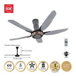
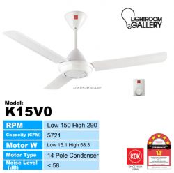
    @spin55 what's your opinion on using this hack with ceiling fan? could it be used?
    I think the channel mention that it depends on the fan itself if it can be powered by half wave dc.
    I have these ones at home, one with a knob speed controller and another using remote

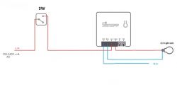
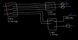
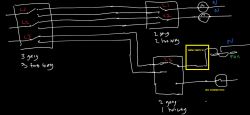
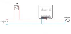
    Modifying Tuya Mini for No-Neutral Installation: Experiences with Diode Polarity Reversal? Modifying Tuya Mini for No-Neutral Installation: Experiences with Diode Polarity Reversal?
  • #33 20536172
    spin55
    Level 17  
    All the assembly would be valid, except that it would be necessary to "play" with these three components. How many watts does it consume?

    Modifying Tuya Mini for No-Neutral Installation: Experiences with Diode Polarity Reversal?
  • ADVERTISEMENT
  • #34 20536194
    ferbulous
    Level 18  
    spin55 wrote:
    All the assembly would be valid, except that it would be necessary to "play" with these three components. How many watts does it consume?

    Modifying Tuya Mini for No-Neutral Installation: Experiences with Diode Polarity Reversal?


    I might need to get the tuya mini with power monitoring to verify the wattage
    According to the specs sheet, these are the estimates

    Motor W : Low 14.1 – 19.9
    High 67.5 – 82.5
  • #35 20536220
    spin55
    Level 17  
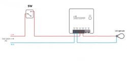
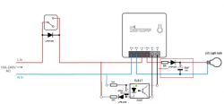
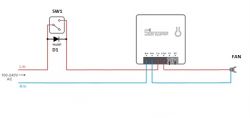
    Do you know that you can control it remotely with SW Closed and this configuration?:

    Modifying Tuya Mini for No-Neutral Installation: Experiences with Diode Polarity Reversal? Modifying Tuya Mini for No-Neutral Installation: Experiences with Diode Polarity Reversal?
  • #36 20536279
    ferbulous
    Level 18  
    spin55 wrote:
    Do you know that you can control it remotely with SW Closed and this configuration?:

    Modifying Tuya Mini for No-Neutral Installation: Experiences with Diode Polarity Reversal? Modifying Tuya Mini for No-Neutral Installation: Experiences with Diode Polarity Reversal?


    This would require neutral behind the switch, correct? And you'd need to lock the switch in always on position
  • Helpful post
    #37 20536339
    spin55
    Level 17  
    ferbulous wrote:
    And you'd need to lock the switch in always on position


    This is correct, but the neutral wire is already in the ceiling.

    Modifying Tuya Mini for No-Neutral Installation: Experiences with Diode Polarity Reversal?

    This is how I have ceiling lights in my house.
  • #38 20536356
    ferbulous
    Level 18  
    spin55 wrote:
    ferbulous wrote:
    And you'd need to lock the switch in always on position


    This is correct, but the neutral wire is already in the ceiling.

    Modifying Tuya Mini for No-Neutral Installation: Experiences with Diode Polarity Reversal?

    This is how I have ceiling lights in my house.


    I see, so this is another alternative just that it turns off openbk if the switch is toggled off.
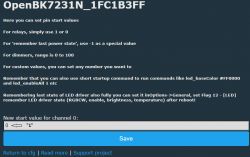
    And that startup command turns on the relay once it boots up, and remote control is back.
    I have a 2 way switch that controls a ceiling fan which I'm still figuring out if it's safe to use the hack
  • ADVERTISEMENT
  • #39 20536416
    spin55
    Level 17  
    ferbulous wrote:
    I see, so this is another alternative just that it turns off openbk if the switch is toggled off.
    And that startup command turns on the relay once it boots up, and remote control is back.


    OK

    ferbulous wrote:
    I have a 2 way switch that controls a ceiling fan which I'm still figuring out if it's safe to use the hack


    Two ways for what? One for light and one for fan?. Doesn't control light and fan with remote control? If so, you only need one way.

    Regards
  • #40 20536534
    ferbulous
    Level 18  
    spin55 wrote:
    Two ways for what? One for light and one for fan?. Doesn't control light and fan with remote control? If so, you only need one way.


    Separate lights and fan, just that each have 2 way wiring

    Modifying Tuya Mini for No-Neutral Installation: Experiences with Diode Polarity Reversal?
  • #41 20536620
    spin55
    Level 17  
    Mini switch for fan. Same thing if you want individual manual control of each light. Same assembly as before but you would need a mini switch for each line.

    Modifying Tuya Mini for No-Neutral Installation: Experiences with Diode Polarity Reversal?
  • #42 20536689
    ferbulous
    Level 18  
    spin55 wrote:
    Same assembly as before but you would need a mini switch for each line.

    yes, that's what I plan to do with all the lights
    I'm just not sure if it's safe to use the hack for the ceiling fan, I mean would it affect the fan motor or something since it's using half wave dc
  • #43 20536819
    spin55
    Level 17  
    ferbulous wrote:
    I'm just not sure if it's safe to use the hack for the ceiling fan, I mean would it affect the fan motor or something since it's using half wave dc


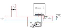
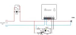
    With this assembly you should not have a problem with the fan:

    Modifying Tuya Mini for No-Neutral Installation: Experiences with Diode Polarity Reversal?

    Forget about this assembly, because as you say, it works with pulsating direct current and needs alternating current to work. And you can't suppress the diode because it would blow up the electrolytic capacitor. Thanks for making me see. what a mistake.

    Modifying Tuya Mini for No-Neutral Installation: Experiences with Diode Polarity Reversal?

    Don't even try it because the impedance of the motor winding is too small in DC, it may damage the fan!!!

    Added after 2 [hours] 36 [minutes]:

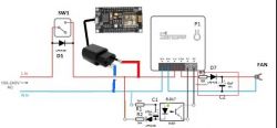
    I think this assembly might work with the fan:

    Modifying Tuya Mini for No-Neutral Installation: Experiences with Diode Polarity Reversal?
  • ADVERTISEMENT
  • #45 20538103
    ferbulous
    Level 18  
    spin55 wrote:
    spin55 wrote:
    I think this assembly might work with the fan:


    I did tests with a hand dryer because I don't have a fan and I can confirm that this setup only works when the wall switch is closed. AC devices do not work with a single half cycle.

    https://www.elektroda.com/rtvforum/topic3971605.html#20537876

    Regards


    Thanks for the detailed explanation on how it works with dc or ac
    From your test, the hand dryer (ac) didn’t turn on when the relay is toggled on with half wave dc (switch in open position).
    So if my fan is using dc motor, then technically half wave dc could still power the motor as normal with no issues?

    Also, since you’ve excluded the fusible resistor in the diagram with fan, is it advisable to do that since the youtube channel did mention fusible resisor is needed for safety reason
  • #46 20538272
    spin55
    Level 17  
    ferbulous wrote:
    o if my fan is using dc motor, then technically half wave dc could still power the motor as normal with no issues?


    In my opinion, I would only have to choose the diodes D1 and D7 based on the consumption in amps of the load.
    The rest would be the same as the devices that have power supplies that are connected to AC but internally work with DC. That's why I think that the DC fan could work by "playing" with the diodes and the value of C2, increasing it if the ripple is excessive.

    Modifying Tuya Mini for No-Neutral Installation: Experiences with Diode Polarity Reversal?

    These are the characteristics that you have to pay attention to when choosing the diodes:

    Modifying Tuya Mini for No-Neutral Installation: Experiences with Diode Polarity Reversal?

    ferbulous wrote:
    Also, since you’ve excluded the fusible resistor in the diagram with fan, is it advisable to do that since the youtube channel did mention fusible resisor is needed for safety reason


    It's right, all assemblies should have a protection fuse for safety reason!!.

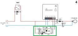
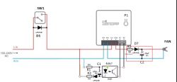
    Resistor R3 is there to protect D7 when you plug the entire assembly into the mains AC for the first time. At that instant the capacitor is discharged and there is a significant current peak that must not exceed the maximum supported by D7. It also protects if there is an excessive consumption of C2 or fan due to failure. During the negative half-wave, D7 acts as a switch and prevents C2 from being destroyed which begins to discharge through the fan by supplying it with the current it needs. This is repeated every 10 milliseconds (for a mains frequency of 50Hz) and the set of C2 and fan impedance have to make C2 hold as much charge as possible.

    NOTE: Before trying the assembly 4 with DC fan I would make sure what type of internal power supply it has.

    NOTE2: Please, if someone is not sure what it does, don't try it. This can be dangerous for people if they don't understand what they are doing and why.

    Regards
  • #47 20539610
    ferbulous
    Level 18  
    spin55 wrote:
    NOTE: Before trying the assembly 4 with DC fan I would make sure what type of internal power supply it has.

    Hi, how do I check for the internal power supply? Any specific ones I need to look out for

    spin55 wrote:
    These are the characteristics that you have to pay attention to when choosing the diodes:

    Since i'm already using IN4007 diodes, would that be sufficient?

    spin55 wrote:
    Resistor R3 is there to protect D7 when you plug the entire assembly into the mains AC for the first time. At that instant the capacitor is discharged and there is a significant current peak that must not exceed the maximum supported by D7. It also protects if there is an excessive consumption of C2 or fan due to failure. During the negative half-wave, D7 acts as a switch and prevents C2 from being destroyed which begins to discharge through the fan by supplying it with the current it needs. This is repeated every 10 milliseconds (for a mains frequency of 50Hz) and the set of C2 and fan impedance have to make C2 hold as much charge as possible.


    Thanks for the detailed explanation
  • #48 20540862
    spin55
    Level 17  
    ferbulous wrote:
    Since i'm already using IN4007 diodes, would that be sufficient?


    Yes, to check how many watts you can handle with that value of C2 with the test of accumulating light bulbs.
    1.- SW1 in open position and remotely controls the relay from the web.
    2.- Add another bulb in parallel and keep adding bulbs until they blink.
    3.- You will already have a reference of the watts that you can control with those components.
    ----------------------------
    I used UF5408 diodes instead of 1N4007 because it was what I had to do the test.
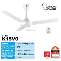
    With these diodes and a value of 470uF/450V for C2, I would test the model K15V0 fan.

    ferbulous wrote:
    Hi, how do I check for the internal power supply? Any specific ones I need to look out for


    If you are sure that the fan is DC, don't worry, you can connect it without fear.
    Do the test with C2 (470uF/450V), D1 and D7 (UF5408) and Fan model K15V0.

    Modifying Tuya Mini for No-Neutral Installation: Experiences with Diode Polarity Reversal? Modifying Tuya Mini for No-Neutral Installation: Experiences with Diode Polarity Reversal? Modifying Tuya Mini for No-Neutral Installation: Experiences with Diode Polarity Reversal?
  • #49 20542441
    ferbulous
    Level 18  
    spin55 wrote:
    Do the test with C2 (470uF/450V), D1 and D7 (UF5408) and Fan model K15V0.

    I can't quite confirm yet if the fan that comes with speed regular (K15V0) is using dc motor, I do believe the remote controlled fan model is using ac

    spin55 wrote:
    If you are sure that the fan is DC, don't worry, you can connect it without fear.

    what's the worst that could happen if tested with AC device ? seems like from your testing with ac hair dryer, the device just doesn't turn on with half wave

    Considering the circuit is still powered by half wave when the switch is off position (half wave dc only), could i use that so it always powers the esp8266?
    Modifying Tuya Mini for No-Neutral Installation: Experiences with Diode Polarity Reversal?
  • #50 20542515
    spin55
    Level 17  
    ferbulous wrote:
    Considering the circuit is still powered by half wave when the switch is off position (half wave dc only), could i use that so it always powers the esp8266?


    Yes

    ferbulous wrote:
    I can't quite confirm yet if the fan that comes with speed regular (K15V0) is using dc motor, I do believe the remote controlled fan model is using ac


    With this assembly:

    1.- SW1 Closed. Relay On via web. It should work.
    2.- SW1 Opened. Relay On via web. If there is movement it is Fan DC.

    Do the same for the other fan if you want to compare.

    Modifying Tuya Mini for No-Neutral Installation: Experiences with Diode Polarity Reversal?
  • #51 20543240
    ferbulous
    Level 18  
    spin55 wrote:
    Yes

    Awesome, I have some diy mmwave sensors that could really benefit from this, just have it hidden away in the ceiling under the light fixtures

    spin55 wrote:
    With this assembly:

    1.- SW1 Closed. Relay On via web. It should work.
    2.- SW1 Opened. Relay On via web. If there is movement it is Fan DC.

    Do the same for the other fan if you want to compare.

    Thanks for the instructions, i'm gonna start small with the stand fan first
    Wouldn't want the wife to get angry if the ceiling fan stops working
  • #52 20745181
    franfj
    Level 5  

    This is a great idea. I've successfully used it on Aubess mini switches.

    The easy way to start is with just a diode in series in the Line In, noting the polarity which powers on the mini-switch, and build the rest of the circuit according to that polarity.

    I wonder if it's better to always put the 400V capacitor near the bulb, or avoid it if the light does not blink? Not having the capacitor allows to put it in small spaces.
  • #53 20746946
    spin55
    Level 17  
    franfj wrote:
    I wonder if it's better to always put the 400V capacitor near the bulb, or avoid it if the light does not blink? Not having the capacitor allows to put it in small spaces.


    Logically, if the bulb does not blink without a capacitor, you don't need to put it in.

    The reason for putting the capacitor is so that the bulb does not flicker during the negative half cycle of the mains wave. The diode acts as a switch that only conducts during the positive half cycles and recharges the capacitor. During the negative half cycle, the diode does not conduct and the capacitor keeps the light bulb on during the 10 milliseconds that the wave lasts (for a 50Hz network).

    It could remove the capacitor if the mains frequency increases. In this case, you could also remove the diode and the protection resistor. The light bulb would turn off during the negative half cycle, but we would not perceive it due to the persistence of images on the retina.


    Circuit diagram with LED bulb and capacitor connections.

    Greetings
  • #54 20772394
    franfj
    Level 5  

    Sounds logical.

    Any recommendations for the 10R fusible resistor? I tried with one of 1/2W and worked for about a month, but it got fused. Maybe it was a bad quality resistor, or maybe it was not well calculated.

    The theory is that this resistor gets a lot of power for a short time during the power on because of charging the capacitor, but since all the power for the LED lamp passes through it, it must also be able to dissipate the corresponding current.

    In my calculations, 1/4W for 10R should be enough for up to 30W lamp, 1/2W for up to 50W lamp, am I right?
  • #55 20772829
    spin55
    Level 17  
    The 50W of the LED lamp refers to a given alternating current supply and a cosine of phi, so P=V.I.cos phi.

    There you could calculate the effective current intensity consumed by the lamp, which would be I=P/(V.cos phi). For a mains voltage of 230V/50Hz and a cosine of phi=1, the current would be 0.227A.

    Therefore, the power dissipated in the resistor would be P=I(squared).R, which would result in 0.515W. But the electrical voltage allows a variation margin of +-10%, therefore you must always allow for excess. In this theoretical case I would try a resistor of 1W or the nearest standard value.

    But you will see in the videos that here we are not applying an alternating current and therefore the voltage and current calculations differ.

    https://www.youtube.com/watch?v=sekdEc5wU6k
    https://www.youtube.com/watch?v=J8lNkVzukSM

    Greetings
  • #56 20775066
    franfj
    Level 5  

    Right, that's the formula that I've used. I forgot the 10% variations on 230V... and I didn't remember well the power of my LED lamp, I thought it was 40W but after checking, it was actually 55W so 1/2W is clearly not enough.
  • Helpful post
    #58 20894879
    MyProjectBox
    Level 1  
    >>20531832
    Hi I'm the author of the NO-NEUTRAL circuit youtube video, for the Sonoff mini-R2. I'm sorry to see this discussion so late 😪. I could of helped to clarify some things. I appreciate all the good work you are doing. I might do a youtube video a tuya mini NO-NEUTRAL circuit, if you don't mind?

    Added after 12 [minutes]:

    @franfj have you tried my new NO-NEUTRAL circuit yet?
  • #59 20894932
    p.kaczmarek2
    Moderator Smart Home
    That's a great video, @MyProjectBox ! I haven't personally tried it because I am lucky enough to have both L and N wires routed to switches in my house, but I am confident that many houses in Poland don't have N available so your no-neutral mod will certainly come useful for our users.

    By the way, if you are interested in making some kind of OBK-related video (flashing guide or something), let me know, I can help with that, maybe even provide schematics or other media.

    Added after 40 [seconds]:

    We can feature your video on our page if you're interested:
    https://openbekeniot.github.io/webapp/devicesList.html
    Helpful post? Buy me a coffee.
  • #60 20895043
    franfj
    Level 5  

    MyProjectBox wrote:
    >>20531832
    Hi, I'm the author of the NO-NEUTRAL circuit YouTube video for the Sonoff mini-R2. I'm sorry to see this discussion so late 😪. I could have helped to clarify some things. I appreciate all the good work you are doing. I might do a YouTube video on the Tuya mini NO-NEUTRAL circuit if you don't mind?

    Added after 12 [minutes]:

    @franfj have you tried my new NO-NEUTRAL circuit yet?

    Not yet, but I have a project in mind to use it.

    Thanks for sharing it!

Topic summary

The discussion revolves around modifying the Tuya Mini switch for no-neutral installations, specifically addressing issues related to diode polarity reversal and relay toggling from a wall switch. Users share experiences and suggestions for circuit modifications, including flipping diodes and capacitors to ensure proper operation with the positive half-cycle of AC voltage. Safety measures, such as using fusible resistors, are emphasized. Participants also explore the feasibility of using this setup with ceiling fans and other AC devices, noting the importance of understanding the power requirements and potential risks associated with half-wave DC operation. Successful configurations and troubleshooting steps are shared, along with links to relevant diagrams and videos.
Summary generated by the language model.
ADVERTISEMENT