logo elektroda
logo elektroda
X
logo elektroda

[TYWE2S/ESP8226] Smart plug with RGBW backlight MOKO TX-DE02 and USB charger

p.kaczmarek2  3 2286 Cool? (0)
Listen:

TL;DR LABEL_AI_GENERATED

  • The MOKO TX-DE02 / YX-DE02 smart plug combines relay control, two 5V 2.1A USB ports, and RGBW backlight LEDs in one Wi‑Fi socket.
  • Inside, it uses a TYWE2S module with exposed GPIO0 and a PCB pin map for the relay, button, and separate R, G, B, and W LED channels.
  • A four-pack cost $28, or about $7 each.
  • Flashing uses esptool.py with 3.3V, GND, RX, TX, and GPIO0 tied low at boot, followed by a power-cycle to start the new firmware.
  • Tasmota’s Maxcio DE02 template makes the plug’s relay and RGBW lighting work, but the USB ports stay uncontrolled and there is no energy meter.
AI summary based on the discussion. May contain errors.

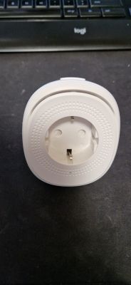
Hello, I will present here the interior and configuration of Tasmota for a rather unusual WiFi-controlled plug/socket with backlight composed of RGBW diodes. As a standard, we will free the nest from the cloud and prepare it to work with HA. The plug described here offers basically three functions: relay control via the application, two USB ports (unfortunately without control) 5V 2.1A and effective backlight (RGB and W). This topic, like the previous one, was created in cooperation with my friend @dedamraz.

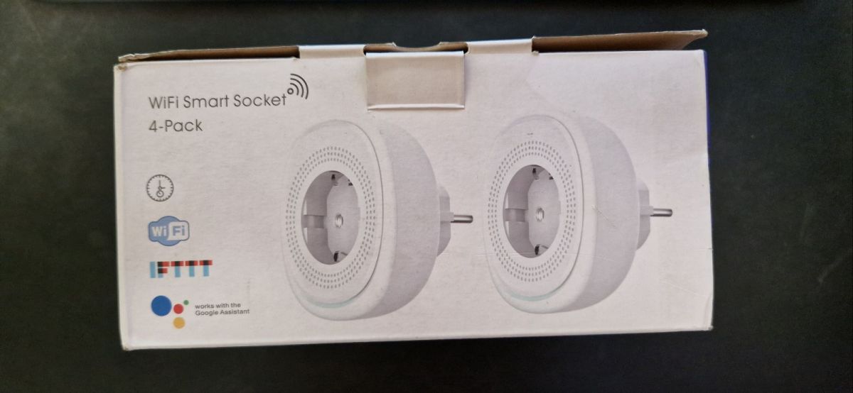
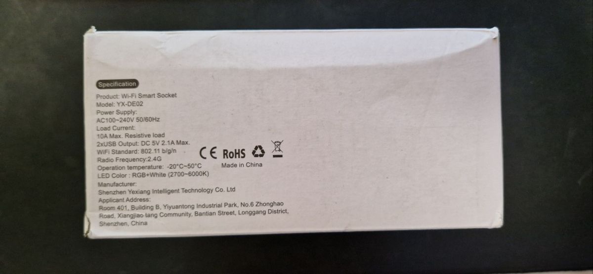
The product was purchased in a stationary store in Serbia. One package was purchased, here a four-pack, for $28 (about $7 each):
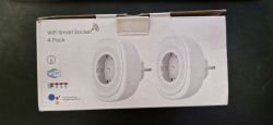
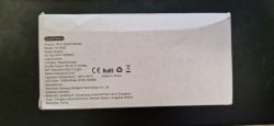
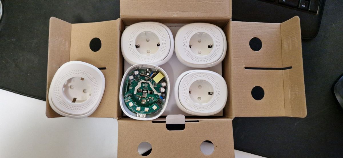
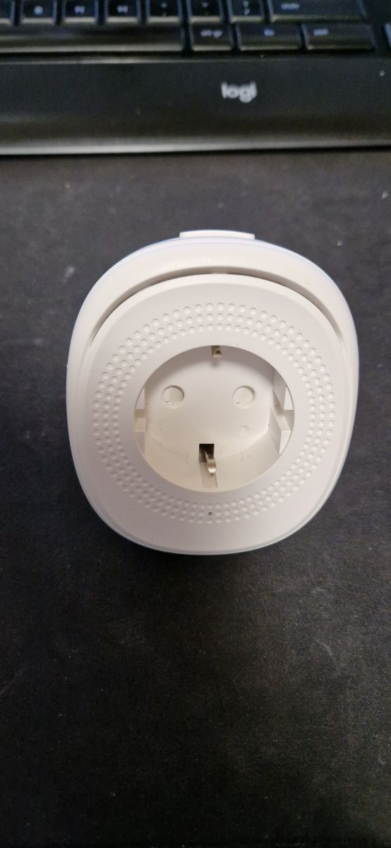
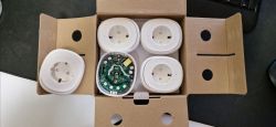
Contents:
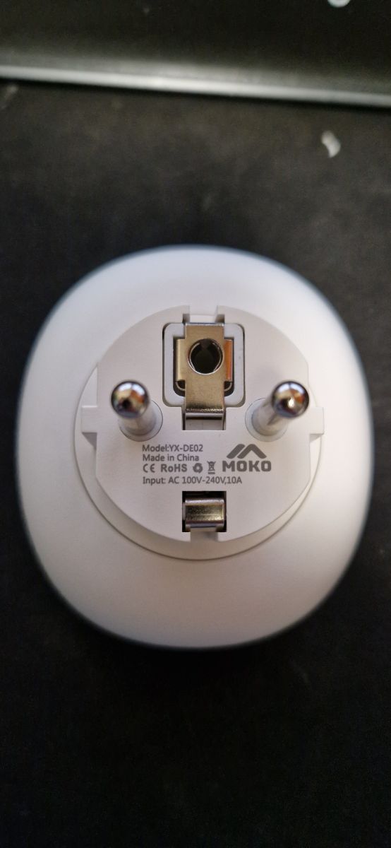
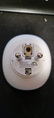
At the bottom of the plug is the model name - YX-DE02:
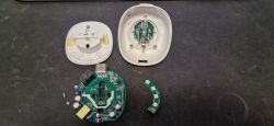
You have to use force to get inside. You should pry the cover and then unfortunately you need to desolder the pins of the socket i.e. flux and braid are necessary.
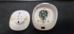
The plugin has a characteristic backlight, consisting of four RGB LEDs:
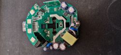
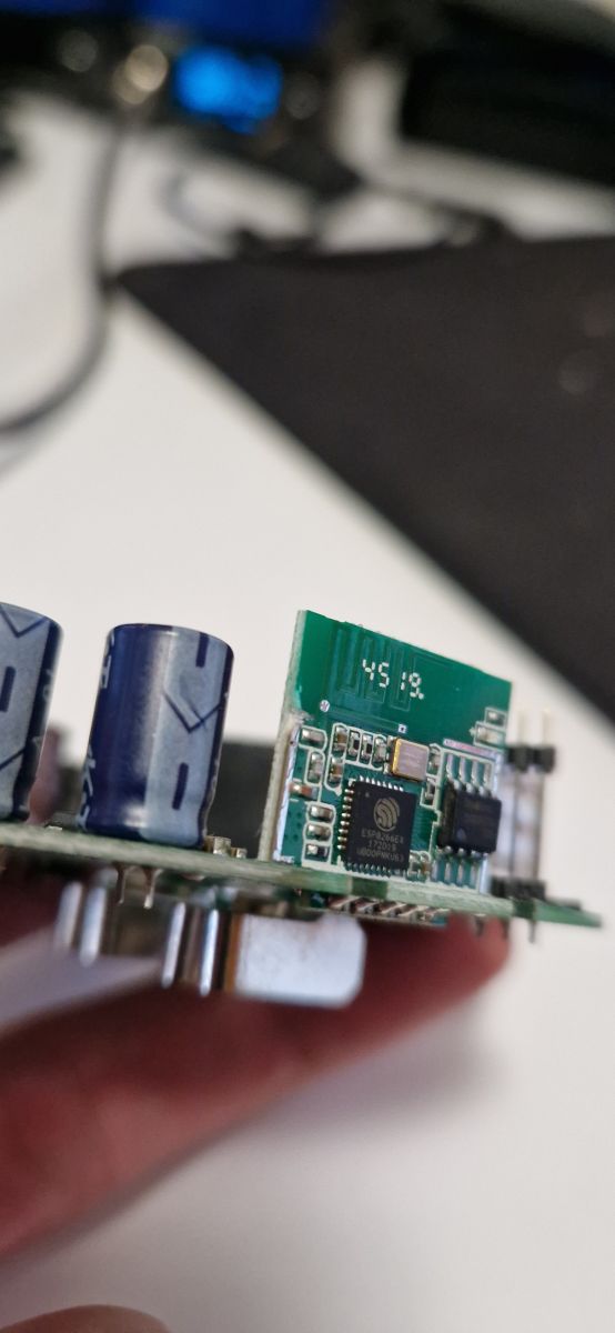
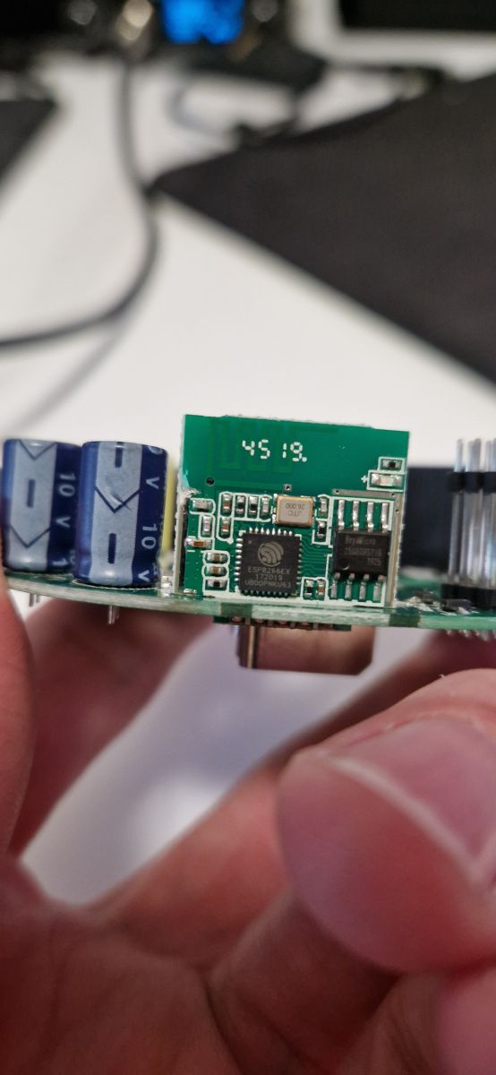
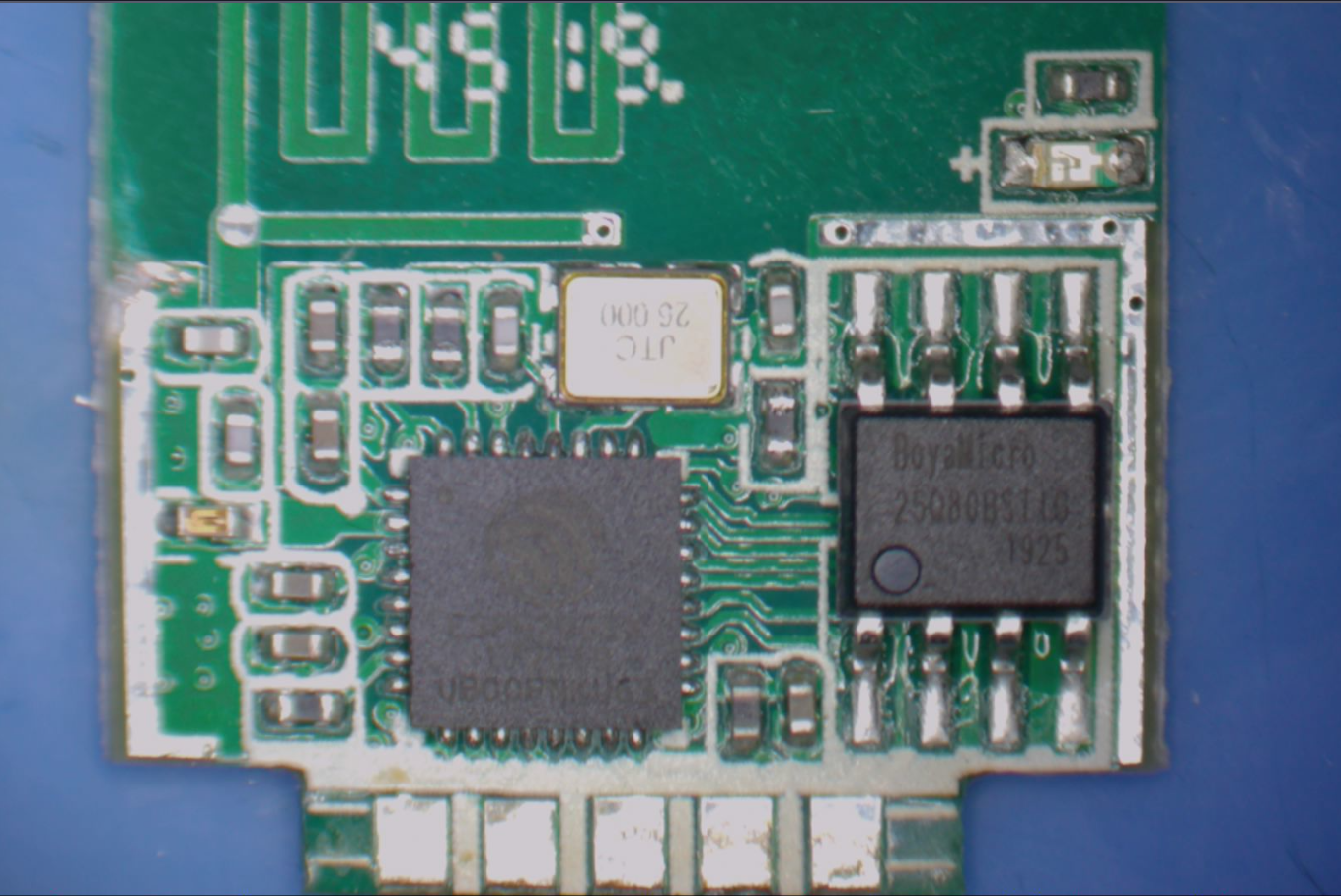
The product uses TYWE2S:
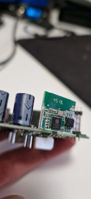
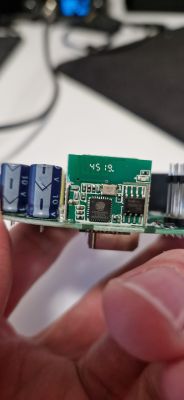
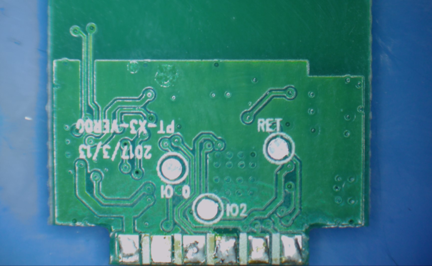
It is not 100% ordinary TYWE2S, but it has standard pins. GPIO0 is available on the back of the module:
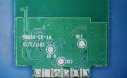
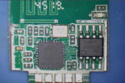
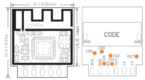
Here are the pinouts of the TYWE2S:
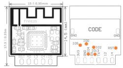

A brief PCB analysis shows the following GPIO ESP roles:
IO5 - LED strip W (PWM??)
IO4 - LED status
RX-Relay
IO13 - LED strip G (PWM??)
TX - Btn
IO12 - LED strip R (PWM??)
IO14 - LED strip B (PWM??)
So we have 4 LED colors, RGB and W, separately white.

The batch can be uploaded via esptool.py . There are various methods, but I only solder 3.3V, GND, RX, TX and GPIO0 to ground (bootloader mode), then connect the power supply (so that GPIO0 is grounded at boot time) and use esptool. Then, for the firmware to start, you need to disconnect GPIO0 from ground and perform a power off/on cycle.

Tasmota setup
The Tasmota configuration of this device is available on the web:
https://templates.blakadder.com/maxcio_YX-DE02.html
So there's nothing to mess around with.
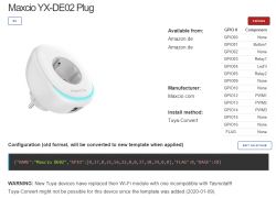
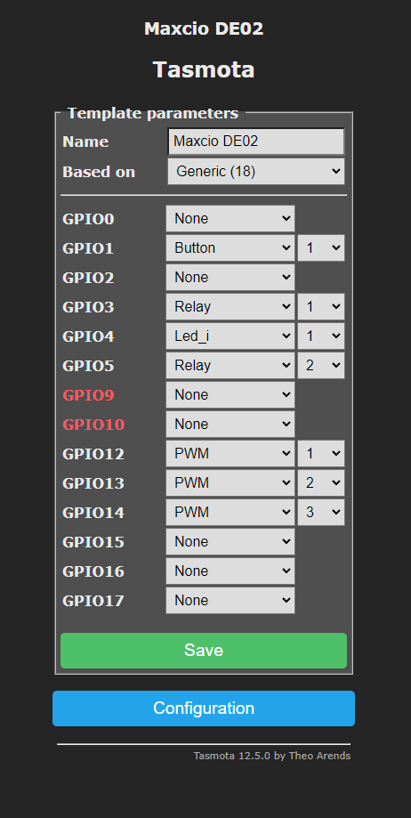
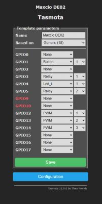
We upload the template:

{"NAME":"Maxcio DE02","GPIO":[0,17,0,21,56,22,0,0,37,38,39,0,0],"FLAG":0,"BASE":18}

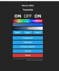
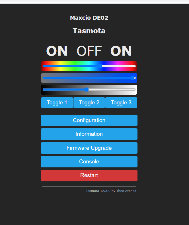
And everything works:

The buttons visible on the panel are used to control the RGB LED, separately the white lighting and the relay.

LED effects
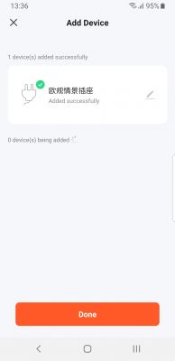
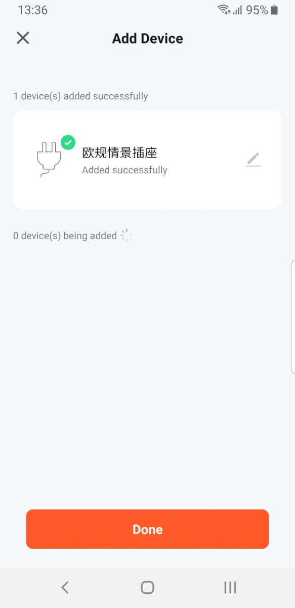
This time tested with the manufacturer's application. First firing:
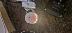
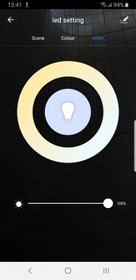
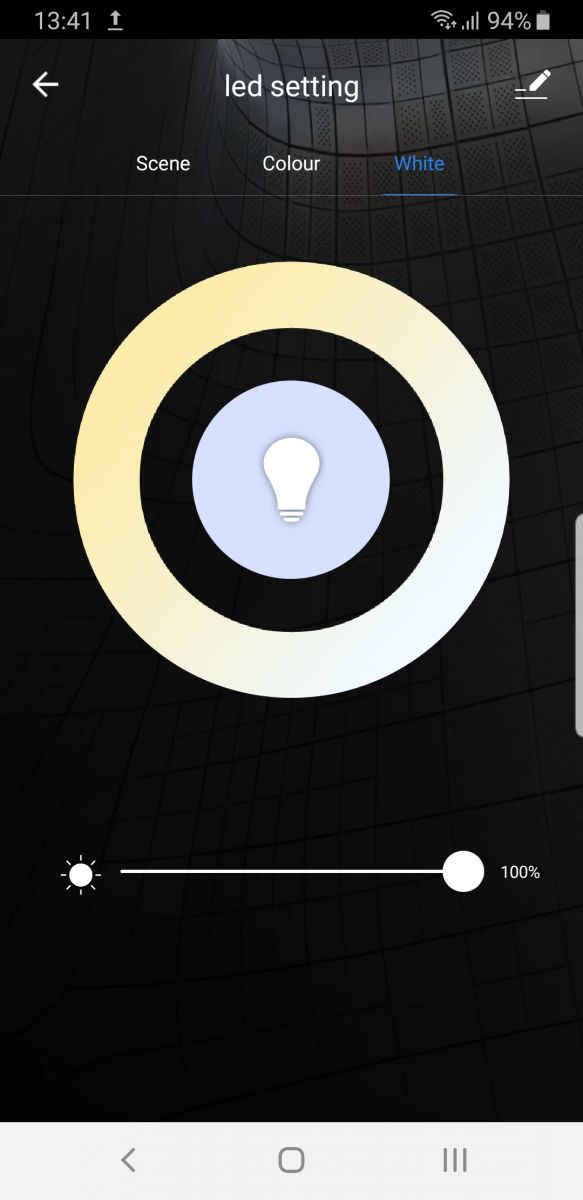
View in the application:
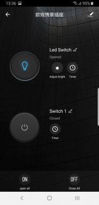


The application has full control of the socket and LEDs.

Summary
Thank you to my colleague @dedamraz for another opportunity to jointly (on my part remotely) change the product firmware. Colleague @dedamraz also began to be very active in working on OpenBeken which is also commendable. This plug, in turn, will serve us, among others. for tests Tasmota Devices Groups for pairing OBK with Tasmota.
As for the product itself - it is the first smart plug z RGBW backlight I haven't seen anything like that. This is new to me, but does it have any use?
It is also a pity that we do not have on / off control over the USB ports, but this is what the manufacturer has already decided.
If the product had an energy meter (usually BL0942 or BL0937), it could be nicely scripted so that, for example, the color reflects the power consumed by the connected device at a given moment, but without it, these colored LEDs are probably just wasted ...
I attach a backup of the ESP batch.
Attachments:
  • RGB MOKO TX-DE02.zip (321.16 KB) You must be logged in to download this attachment.

About Author
p.kaczmarek2
p.kaczmarek2 wrote 14797 posts with rating 12955 , helped 659 times. Been with us since 2014 year.

Comments

jkwim 15 May 2023 04:50

RGB Smart Plugs have been around for a while. I use few Tasmota devices as indicator devices from MQTT network. That is I can change the color of the LED ring based on status of some other device connected... [Read more]

p.kaczmarek2 15 May 2023 08:17

So there is a RGB + power meter version, as I can see on your screenshot. Nice! Is it possible to script Tasmota to make somehow colour go gradually with current power consumption? Colder colours for low... [Read more]

jkwim 15 May 2023 22:30

I am using UK plugs. They don't come with energy monitoring. However there should not be a problem to write a script to change color on power values. [Read more]

FAQ LABEL_AI_GENERATED

TL;DR: This FAQ helps Tasmota users flash a $7 YX-DE02 RGBW smart plug; the key warning is “desolder the pins” before full access. It solves TYWE2S wiring, GPIO mapping, RGBW control, USB limits, and Home Assistant integration for ESP8266 Tuya plugs. [#20560046] Why it matters: A cloud-dependent RGBW plug becomes a local Home Assistant device, but mains disassembly and GPIO0 flashing create real failure risks.

Alternative Chip or platform Best fit Thread-specific limitation
Tasmota on YX-DE02 TYWE2S / ESP8266 Local relay and RGBW control USB ports are not switchable
OpenBeken Tuya-family firmware project Pairing OBK devices with Tasmota groups Discussed as a separate test path
Manufacturer app Cloud app Full original socket and LED control Keeps the device cloud-tied

Key insight: The YX-DE02 exposes relay, button, status LED, and 4 RGBW PWM channels to Tasmota. The missing energy meter limits power-based color automation.

Quick Facts

  • The four-pack cost $28, or about $7 per plug, and each unit includes two 5 V, 2.1 A USB ports. [#20560046]
  • The device label shows model YX-DE02, while the Tasmota template names the hardware “Maxcio DE02”. [#20560046]
  • The plug uses a TYWE2S ESP8266 module, with GPIO0 available on the back for bootloader flashing. [#20560046]
  • The RGBW backlight uses four RGB LEDs plus a separate white channel, mapped across IO5, IO12, IO13, and IO14. [#20560046]
  • A user reports using RGB smart plugs as MQTT status indicators and timer-controlled night lamps. [#20580508]

How do you flash Tasmota onto a MOKO or Maxcio YX-DE02 smart plug with a TYWE2S ESP8266 module?

Flash Tasmota by wiring the TYWE2S module to a 3.3 V serial adapter and using esptool.py.
  1. Solder 3.3 V, GND, RX, TX, and GPIO0.
  2. Hold GPIO0 to ground during power-up.
  3. Upload firmware, then remove GPIO0 from ground and power-cycle. The thread confirms this method on the YX-DE02 plug. Use only 3.3 V logic for the ESP8266 module. [#20560046]

What is a TYWE2S module, and how is it used inside ESP8266-based Tuya smart plugs?

TYWE2S is the WiFi module used as the plug’s ESP8266 controller. “TYWE2S is an ESP8266-based Tuya WiFi module that runs device firmware, exposes standard GPIO pins, and connects the smart plug’s relay, button, LEDs, and serial flashing pads.” In this YX-DE02, it drives the relay, status LED, button input, and RGBW lighting channels. [#20560046]

Which GPIO pins control the relay, button, status LED, and RGBW backlight on the YX-DE02 smart plug?

The YX-DE02 maps relay, button, status LED, and RGBW outputs to seven ESP GPIO signals. RX controls the relay, TX reads the button, and IO4 drives the status LED. The RGBW channels use IO12 for red, IO13 for green, IO14 for blue, and IO5 for white. The thread identifies the LED channels as PWM-capable candidates. [#20560046]

What Tasmota template should be used for the Maxcio DE02 or YX-DE02 RGBW smart plug?

Use the Maxcio DE02 Tasmota template shown for the YX-DE02 RGBW plug. The template is {"NAME":"Maxcio DE02","GPIO":[0,17,0,21,56,22,0,0,37,38,39,0,0],"FLAG":0,"BASE":18}. After loading it, Tasmota exposes separate controls for RGB lighting, white lighting, and the relay. [#20560046]

How do you put the TYWE2S module into bootloader mode using GPIO0 for flashing with esptool.py?

Put the TYWE2S into bootloader mode by grounding GPIO0 before applying power. The author soldered GPIO0, held it to GND, then powered the board. After flashing with esptool.py, disconnect GPIO0 from ground. Then power the plug off and on again so the firmware starts normally. GPIO0 is accessible on the back of the module. [#20560046]

Why do you need to desolder the socket pins when opening the MOKO TX-DE02 or YX-DE02 smart plug?

You need to desolder the socket pins because the internal assembly blocks full PCB access. The thread says the cover must be pried open first. Then the socket pins must be desoldered with flux and braid. This step gives access to the TYWE2S module and flashing points. The edge case is physical damage from force or poor desoldering. [#20560046]

How can the RGBW backlight on a Tasmota smart plug be controlled separately from the relay?

Tasmota controls the RGBW backlight separately by mapping light channels and relay to different GPIO functions. The YX-DE02 template assigns the relay independently from the RGB and white lighting channels. After configuration, the Tasmota panel shows separate buttons for RGB LED control, white lighting, and relay switching. That separation keeps the lamp effect independent from socket power. [#20560046]

What is Tasmota, and why is it used to remove smart plugs from the manufacturer cloud?

Tasmota replaces the stock cloud firmware with local firmware for Home Assistant use. “Tasmota is open firmware for ESP8266 smart devices that enables local web, MQTT, and automation control, reducing dependence on the manufacturer’s cloud.” The thread’s goal was to “free the socket from the cloud” and prepare it for HA. [#20560046]

What is MQTT, and how can RGB smart plugs be used as MQTT status indicator devices?

MQTT lets RGB smart plugs show status from other networked devices. “MQTT is a lightweight messaging protocol where devices publish and subscribe to topics, allowing automations to change an RGB plug’s LED color when another device changes state.” One user runs several Tasmota RGB plugs as indicator devices on an MQTT network. [#20580508]

How can a Tasmota script change an RGB plug’s LED color based on power consumption values?

A Tasmota script can map measured power values to LED colors when the plug reports energy data. The proposed effect uses colder colors for low consumption and warmer colors for higher consumption. A reply states that writing such a script should not be a problem. The YX-DE02 lacks energy monitoring, so it cannot provide the needed power values itself. [#20581843]

What are practical uses for an RGBW smart plug backlight, such as night light mode or device status indication?

Practical uses include night light mode, timer lighting, and MQTT status indication. One user uses RGB smart plugs to display another MQTT device’s status by changing the LED ring color. The same user also describes them as useful night lamps with timer operation. The YX-DE02 adds a separate white channel, which improves simple night-light use. [#20580508]

Why can’t the USB ports on the YX-DE02 smart plug be switched on and off separately in Tasmota?

The USB ports cannot be switched separately because the hardware gives Tasmota no USB control channel. The plug includes two USB ports rated 5 V and 2.1 A. The thread states these ports are “unfortunately without control.” Tasmota can switch the relay and RGBW lighting, but not those USB outputs. [#20560046]

Tasmota vs OpenBeken: which firmware is better for Tuya smart plugs and Home Assistant integration?

Tasmota is the better fit for this YX-DE02 because the plug uses TYWE2S ESP8266 hardware and has a working template. OpenBeken appears in the thread as a separate project for Tuya-family devices and Tasmota Device Groups testing. The author planned to pair OBK with Tasmota, not replace this ESP8266 Tasmota setup. [#20560046]

What safety precautions should be taken when opening and flashing a mains-powered smart plug like the YX-DE02?

Disconnect mains power before opening or soldering the YX-DE02 smart plug. The device contains mains socket hardware and requires force plus desoldering to reach the PCB. Use a 3.3 V serial adapter for TYWE2S flashing. Do not power the ESP8266 serial pins from mains circuitry during programming. The failure risks include shock, lifted pads, and damaged socket pins. [#20560046]

How would an energy monitoring chip like BL0942 or BL0937 improve an RGBW smart plug automation setup?

An energy monitoring chip would let the RGBW light show real-time load visually. The author names BL0942 and BL0937 as typical power-meter chips for this role. With measured power, a script could change LED color according to current consumption. Without such a chip, the YX-DE02’s colored LEDs work mainly as decorative or status lighting. [#20560046]
AI summary based on the discussion. May contain errors.
%}