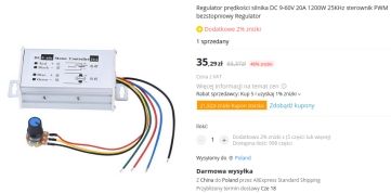
A 60V/20A AliExpress PWM regulator module for DC load control is opened and analyzed, with a focus on motor-speed regulation.
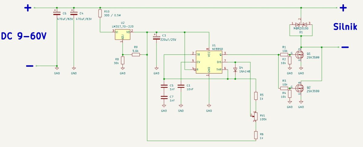
Its circuit uses an NE555 oscillator, 2SK3599 power switches, an MBR20100 diode, and an LM317 supply for the timer.
The PWM carrier frequency is about 20kHz, and duty-cycle adjustment runs from roughly 2.5% to 98%.
The aluminum enclosure is meant to act as a heatsink, but the missing thermopad makes long operation at higher currents doubtful.
Generated by the language model.
Since the early days of the development of electricity and electronics, there has been a need to build regulators to smoothly influence the power dissipated in a load. The first regulators, built as linear regulators, introduced huge losses on the regulating element and, while they worked relatively well for low-power devices (e.g. the speed controller of a tape-shift motor in tape recorders), this was already problematic for medium and high power. This was due to the operation of the power elements in the linear range, much less loss was provided by operation as a key (i.e. open or fully closed with the transient omitted). By controlling the ratio of open to closed time accordingly, it was possible to regulate the power of the load in a smooth manner with minimal losses in the regulator itself. Thus was born the now widely used PWM ( Pulse-Width Modulation ) or Pulse Width Modulation. PWM has found its main application in DC circuits to control the speed (power) of DC motors, heaters or the brightness of light bulbs (traditional as well as LED). The circuit itself, which generates the signal for the actuator, can be implemented in many ways, whether in discrete technology (single transistors) or based on TTL/CMOS digital circuits or even operational amplifiers or specialised PWM controller circuits. It is also easy to implement on probably virtually any microprocessor/microcontroller. One circuit often used as a PWM controller by both amateurs and professionals is the "immortal" NE555.
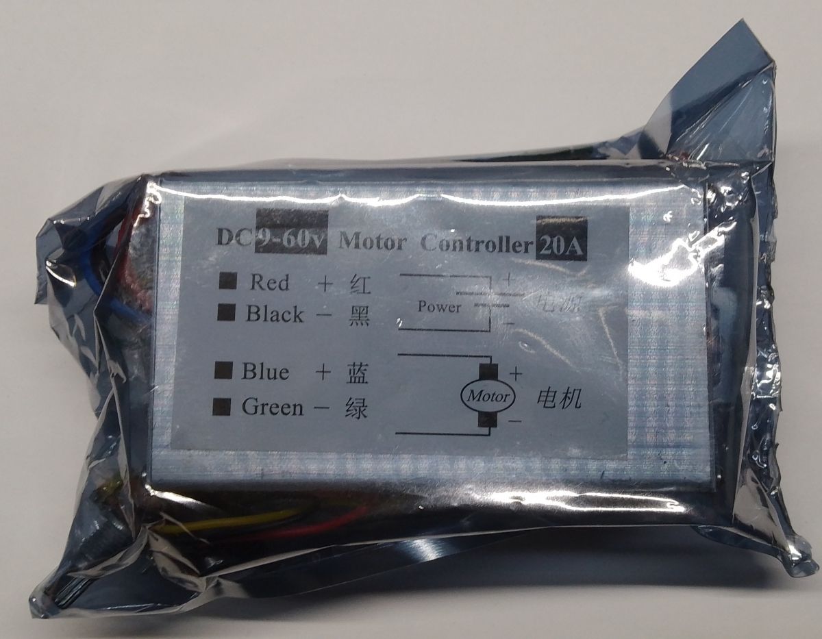
The described regulator module was given to me by a colleague, who purchased several pieces to regulate the speed of the windscreen wiper motors in his car. The module is packaged in an anti-static foil bag;
.
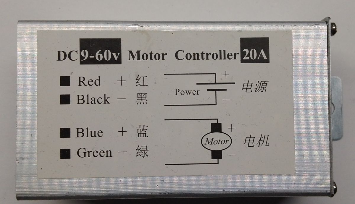
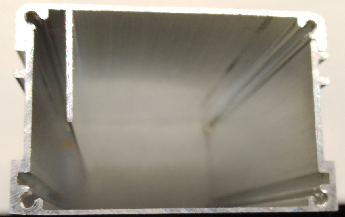
It gives the impression of being solidly built, the housing made of aluminium profiles with steel end caps also acts as a heat sink (although not really, but more on that later).
.
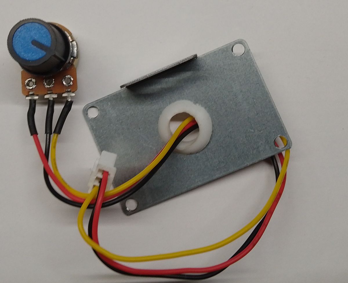
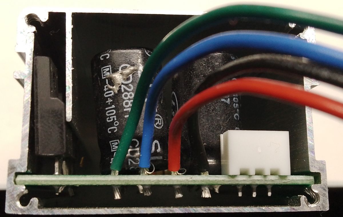
As it were, "included" we get a potentiometer for adjustment together with a knob, in the photo below I have unscrewed the cap to take a look at the interior.
.
As I mentioned, the enclosure is intended to act as a heatsink and is mechanically adapted for this, however, the thermopad between the power components and the enclosure wall was missing;
.
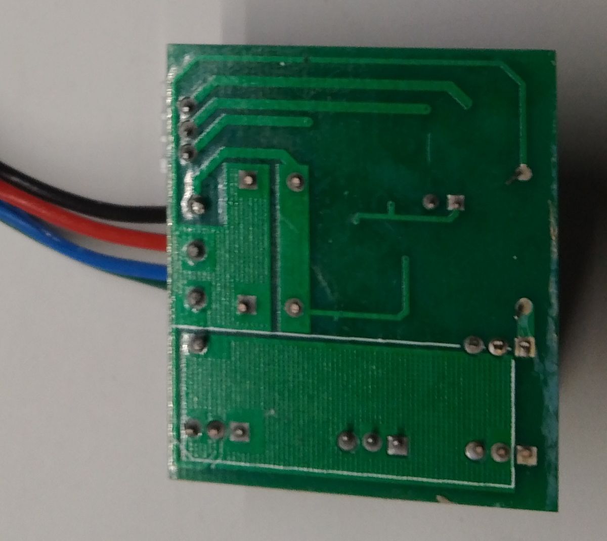
I rather don't anticipate long operation at higher currents.... The regulator board measures 47x40mm and was made as a double-sided board.
<spanclass="notranslate">
.
.
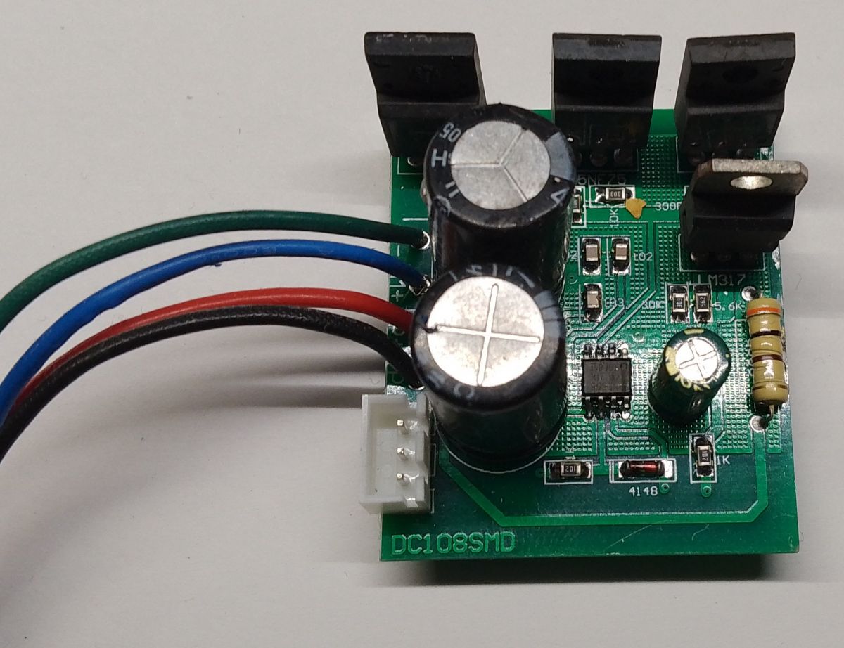
Basically, the whole regulator consists of a dozen or so components and its main component is.... NE555 precisely! I took a moment and redrew the circuit layout from the board;
.
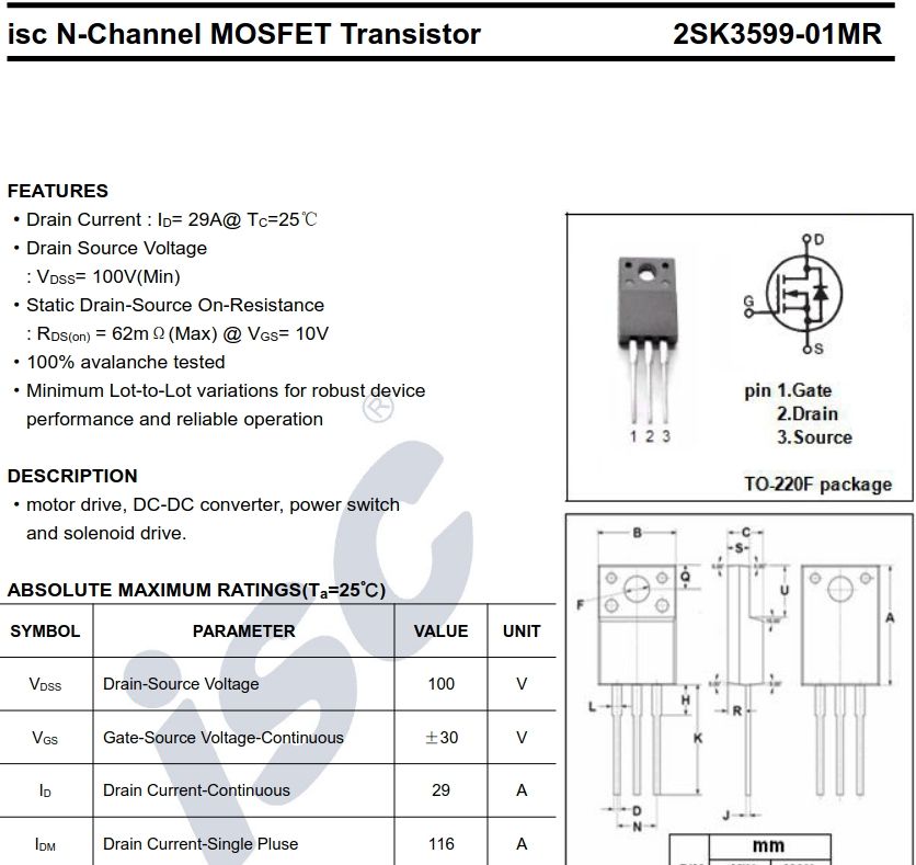
2SK3599 transistors were used as executive keys although the choice of gate resistors is questionable to me....
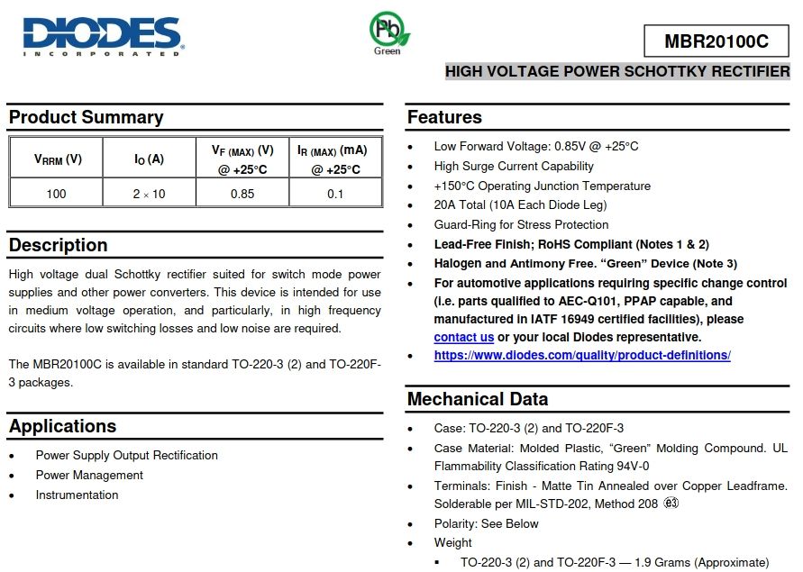
The MBR20100 duodiode is used as the pin suppressor diode;
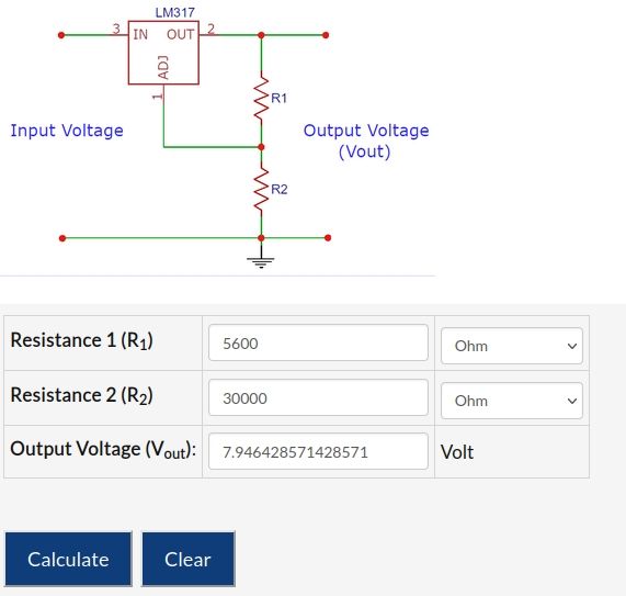
The role of the auxiliary voltage stabiliser for the NE555 is played by an LM317 with somewhat unusually selected resistors fixing the output voltage;
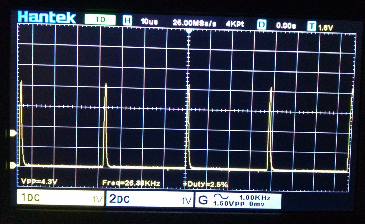
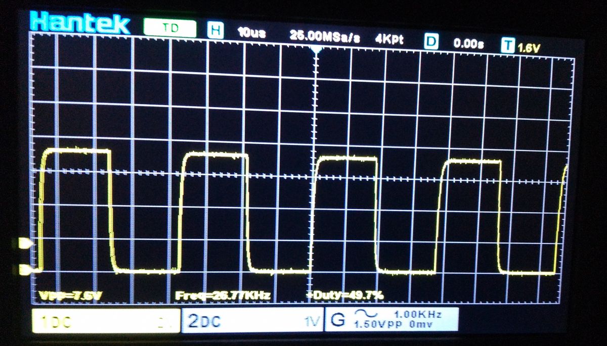
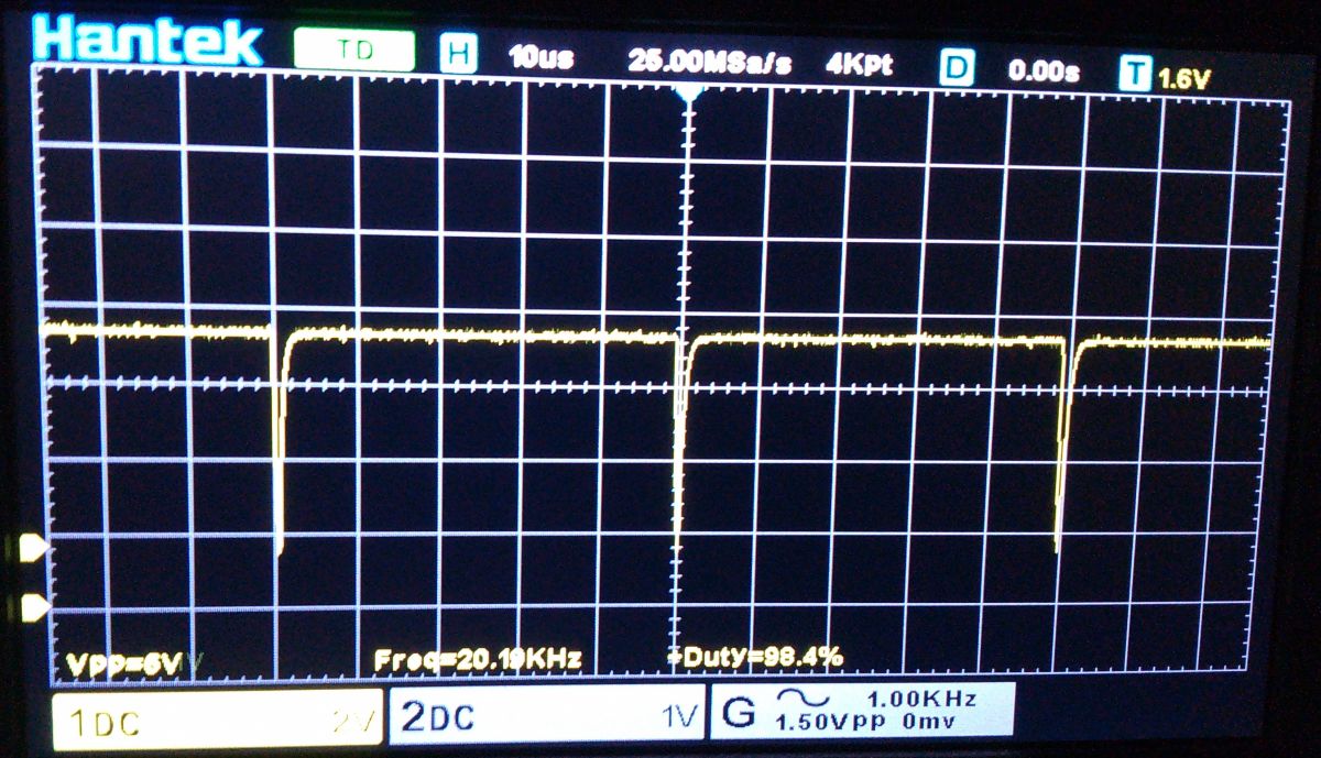
The PWM 'carrier' frequency is ~20kHz which should not produce audible effects when working with inductive loads, the fill is adjustable from about 2.5% to 98%. Below are some photos showing the minimum, average and maximum settings;
.
.
.
In truth, if I were to buy this regulator I would prefer to build it myself .
Errata; .
Gate resistors are not 10k but 300Ω. Sorry for the mistake.
About Author
ArturAVS wrote 26217 posts with
rating 7771 , helped 2296 times.
Live in city Grajewo.
Been with us since 2005 year.
For 2SK3599 in pdf they give Vgs(th) from min. 3V .. max. 5V, so this dividers R1||R3 and R3||R4 on the gates of the mosfets from the supply voltage of 8V will make 4V!!! Maybe someone made a mistake and... [Read more]
ArturAVS
01 Jun 2023 08:01
Probably my mistake unfortunately :-( The gate resistors are marked 301 (300R) and from gate to ground 103 (10k), all elements have the values described on the PCB. Sorry for the confusion. [Read more]
Mateusz_konstruktor
01 Jun 2023 13:57
The LM317 will not give the voltage in the case of a 9V supply voltage, and as it is given in the colleague's diagram.
There's an error here somewhere. [Read more]
ArturAVS
01 Jun 2023 15:57
And where did I say that?
Of course, but committed (or maybe not) by the Chinese designer of the regulator. NE555 works properly from ~4.5V, for this LM317 configuration, the output voltage at 9V power... [Read more]
becalel
06 Jun 2023 13:47
@ArturAVS
Thanks for the insert with the lack of proper pressure on the housing / heat sink, I assemble this regulator to my wife's car because the resistance switch of the airflow force refused to... [Read more]
Przem188
07 Jun 2023 16:48
I am looking for a PWM (24V power supply) that controls the plus and the mass of the engine is the mass of the car. I know that due to other MOSFETs it is more troublesome to design. That's why I haven't... [Read more]
ArturAVS
08 Jun 2023 05:21
Nothing could be more wrong. You just need to reverse the control logic for the P MOSFETs, e.g.;
https://obrazki.elektroda.pl/1939160100_1686193997_bigthumb.jpg
Or use a special driver for... [Read more]
Przem188
08 Jun 2023 06:00
I am looking for a ready-made module with a working voltage of 24V and a load of about 6A.
And apart from one "kit"-in AVT I found nothing. Yes, I designed one myself on two 555 - with adjustable base... [Read more]
Staszek_Staszek
24 Jul 2023 19:13
I wonder why two?
I will make one adjustable for 1/10 - 1/100 Hz because I have not found a ready-made one.
I thought I'd use something like this:
https://obrazki.elektroda.pl/1890338600_1690218708_thumb.jpg... [Read more]
Przem188
24 Jul 2023 20:49
On two 555's to be able to adjust the frequency. [Read more]
An NE555 timer runs as an astable oscillator. Its output drives two 2SK3599 MOSFETs through 300 Ω series resistors, switching the load at ≈20 kHz [Elektroda, ArturAVS, post #20601157]
Why is the missing thermopad a problem?
Without a pad, MOSFET cases do not press against the aluminium shell, raising junction temperature. Users report the risk of early failure when currents exceed 10 A [Elektroda, ArturAVS, post #20601157]
How can I improve cooling on this module?
Add a silicone thermopad or thermal paste between MOSFETs and housing.
Electrical ratings say yes, but ensure gate drive remains ≥4 V after LM317 drop. Add proper thermal interface because 6 A continuous will heat the MOSFETs quickly [Elektroda, ArturAVS, post #20602394]
Can the regulator switch the positive rail instead of ground?
A second 555 lets you vary the carrier frequency independently of duty cycle, useful for very low (1/10 Hz) or adjustable-frequency applications [Elektroda, Przem188, post #20666421]
What gate-drive voltage does the onboard LM317 supply?
With 9 V input, the LM317 outputs about 5.7 V to the NE555, giving ≈5 V gate peaks—enough for 2SK3599 whose Vgs(th) is 3–5 V [Elektroda, ArturAVS, post #20602394]
Are 2SK3599 MOSFETs adequate for 20 A?
Yes. Their Rds(on) is 8.5 mΩ at 10 V gate, yielding ≈1.7 W per device at 20 A [2SK3599 Datasheet]. Adequate cooling remains critical.
What edge-case failures have been observed?
Modules without thermal pads can overheat and shut down within minutes at high load. Mis-labelled gate resistors (initially read as 10 kΩ) risk partial conduction and heat but were corrected to 300 Ω [Elektroda, ArturAVS, post #20601856]
How do I build a simple DIY NE555 PWM driver?
Configure a 555 as astable: Ra, Rb, C set frequency.
Can the carrier frequency be changed on this board?
No trimmer exists. Swap the timing capacitor (now ≈1 nF) to lower frequency, or replace the fixed 47 kΩ resistor with a potentiometer to vary it, as done in dual-555 designs [Elektroda, Przem188, post #20666421]

Comments
For 2SK3599 in pdf they give Vgs(th) from min. 3V .. max. 5V, so this dividers R1||R3 and R3||R4 on the gates of the mosfets from the supply voltage of 8V will make 4V!!! Maybe someone made a mistake and... [Read more]
Probably my mistake unfortunately :-( The gate resistors are marked 301 (300R) and from gate to ground 103 (10k), all elements have the values described on the PCB. Sorry for the confusion. [Read more]
The LM317 will not give the voltage in the case of a 9V supply voltage, and as it is given in the colleague's diagram. There's an error here somewhere. [Read more]
And where did I say that? Of course, but committed (or maybe not) by the Chinese designer of the regulator. NE555 works properly from ~4.5V, for this LM317 configuration, the output voltage at 9V power... [Read more]
@ArturAVS Thanks for the insert with the lack of proper pressure on the housing / heat sink, I assemble this regulator to my wife's car because the resistance switch of the airflow force refused to... [Read more]
I am looking for a PWM (24V power supply) that controls the plus and the mass of the engine is the mass of the car. I know that due to other MOSFETs it is more troublesome to design. That's why I haven't... [Read more]
Nothing could be more wrong. You just need to reverse the control logic for the P MOSFETs, e.g.; https://obrazki.elektroda.pl/1939160100_1686193997_bigthumb.jpg Or use a special driver for... [Read more]
I am looking for a ready-made module with a working voltage of 24V and a load of about 6A. And apart from one "kit"-in AVT I found nothing. Yes, I designed one myself on two 555 - with adjustable base... [Read more]
I wonder why two? I will make one adjustable for 1/10 - 1/100 Hz because I have not found a ready-made one. I thought I'd use something like this: https://obrazki.elektroda.pl/1890338600_1690218708_thumb.jpg... [Read more]
On two 555's to be able to adjust the frequency. [Read more]